|
|
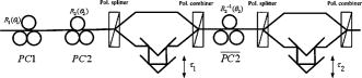
1.IntroductionToday, as the bit rate and the transmission distance of optical fiber communication systems continue to increase, the signal distortion caused by polarization mode dispersion (PMD) in optical fiber channels is becoming a major limitation of system performance improvement. The use of optical PMD compensators (OPMDCs) is effective to reduce the system degrading effects caused by PMD.1, 2, 3 The design of OPMDCs is mainly based on launching the signal into the principal state of polarization (PSP) or a cascade of polarization controllers (PCs) and differential group delay (DGD) elements.1, 2, 3 PSP launch and the OPMDCs with one PC and one fixed or variable DGD element are typical first-order OPMDCs which can only compensate the PMD to first order.2, 3 A cascade of more than one PC and one fixed or variable DGD element compose typical higher-order OPMDCs which can compensate PMD to second order or even higher order.2, 3, 4 All the compensators mentioned above require feedback signals to control the PCs and the variable DGD segments. Especially for the typical higher-order OPMDCs, a very complex software algorithm for the feedback control must be used to correlate the several composed sections to achieve the optimum compensation effects.2, 3, 4 In fact the compensators always tend to get trapped in suboptima and cannot always ensure a better performance than the first-order OPMDCs.3 We demonstrate a new higher-order optical compensator to compensate first-order and higher-order PMD effectively. It just requires one more DGD element and one more PC compared with the first-order OPMDCs using adjustable DGD element.3 And the optimum working condition can be easier to track than the typical higher-order OPMDCs mentioned above. By an advised control method, the compensation scheme can always have better efficiency than the first-order optical compensators. 2.Principle of the Proposed Higher-order Optical Compensator2.1.Proposed Higher-order OPMDC ModelThe frequency-dependent PMD vector can be defined in terms of a Taylor expansion in angular frequency .2 Second-order PMD is decided by the change of DGD with wavelength and the rotation of PSPs with frequency (PSP depolarization).2 The frequency-dependent eigenvector of the transmission matrix of the PMD dominated fiber channel tends to process at a nearly constant PSP depolarization rate within a certain limited bandwidth.2, 5 Based on this theory, we propose the new higher-order OPMDC. The transmission matrix of the proposed compensator can be described by Jones matrix as: where is the deviation from the central carrier angular frequency . The compensator is depicted in Fig. 1. This compensator has two adjustable DGD elements , which are both decided by PSP depolarization rate and DGD in the optical fiber channel. The relations are: . is the transmission matrix of , which is used to transform the optical fiber channel output PSPs to linear polarization states. and are transmission matrices of and , which make opposite transformation. The control information of can be completely obtained from the setting of . And . The two delay sections both have a polarization splitter and a polarization combiner before and after the variable delay. The PMD vector of the proposed compensator realizes procession at the constant PSP depolarization rate. So the PSP depolarization caused by higher-order PMD can be compensated effectively within a certain bandwidth.2, 52.2.Control Algorithm of the Proposed CompensatorThe two delays and , all have a direct and certain relationship with and . So the optimization of them is easy and stable if and are measured exactly. And the widely proposed feedback control using RF spectrum, RF power, eye monitor signal, or degree of polarization2, 3, 4 as feedback control signal still has better efficiency on our proposed compensation scheme than the typical higher-order OPMDCs mentioned in the introduction because of the certain relation between the four variable parameters. The control to and can be decoupled from the setting of variable delays directly. For our proposed compensator, a control method is advised following Ref. 6. First, set to be 0. Use and as a first-order PMD compensator and optimize its compensation effect. Then based on the first-order compensation, optimize , and change the setting of . In the process, the setting of is not changed. The control algorithm can always promise our proposed compensator a better performance than first-order optical compensators while the typical higher-order optical compensators cannot ensure a better performance than first-order optical compensation all the time.3 3.Efficiency Analysis of the Proposed Higher-order CompensatorThe efficiency of our proposed higher-order optical compensator is proved by the comparison with the higher-order compensation scheme of Shtaif 6 which has the same degree of freedom (DOF) with the proposed compensation scheme but different design theory. Like our compensation scheme, the adjustable PCs and DGD elements of the referenced compensator are also related with each other to ensure a better performance than the first-order OPMDCs all the time.6 The Jones transmission matrix of the higher-order optical compensator of Shtaif is6: where , . and stand for the Jones transmission matrices of PCs. here operates the same function as the in our proposed compensator. We applied the two higher-order optical compensators in the same optical fiber communication system model. In the simulations, we launch sequences with raised cosine NRZ pulses in to the optical fiber channel which is built up by a concatenation of 50 birefringent fibers using the scheme suggested by Forno .7 The total fiber length in the model is . The accuracy of the all-order PMD fiber channel has been verified in several published papers.2, 7 The optical compensators under test are placed at the output of the optical fiber channel. After the compensator and before detection, the optical signal is amplified by an erbium-doped fiber amplifier (EDFA) with gain and passes an optical band-pass filter with bandwidth. After directly detection,3 the output electrical signal is filtered by a low-pass 5th-order Bessel filter (bandwidth is , which is optimized in the back-to-back system). Since the gain of EDFA preamplifier is , shot noise and thermal noise can be ignored in the receiver. Signal-spontaneous beat noise and spontaneous-spontaneous beat noise are dominating.8 The noise is expressed as: , .9 The subscript ‘ ’ means signal ‘0’ or ‘1’ is launched at the optical transmitter, refers to the detected signal power, , , and and are the optical band-pass filter bandwidth and the electrical low-pass filter bandwidth. We use Q values and BERs to qualify the system performance. and .8, 9 Here, the subscript ‘ ’ means the values are obtained at the sampling time when the electrical eye opening is the largest at the end of the receiver. We use outage probabilities to measure the efficiency of the two compensation schemes. Outage is defined as the probability of . The input power of the back-to-back system is for . When the efficiency of PMD compensators are discussed, the fiber nonlinearity, chromatic dispersion, and polarization-dependent loss in the optical fiber channel are always neglected and only PMD and noise are taken into account.3 We use the same premises in our simulations, which is effective to estimate the quality of optical PMD compensators.3 We calculate 10,000 independent optical fiber channel realization also with the average to get enough BER samples to calculate outage probability for every input power for the two higher-order optical compensators under test which are applied separately in the same system model. For the two under-tested higher-order compensators, the variable parameters are all decided by DGD and PSP depolarization rate in the optical fiber channel. In the comparison simulations, is gained by measuring DGD at the carrier frequency and is obtained by measuring the change rate of the direction of PMD vector in the vicinity of the carrier frequency . The PCs in the two compensation schemes are all set to try to maintain the PMD vector of the whole system to be zero at the carrier frequency . It must be emphasized that the values of , , PCs, and variable delays can be optimized by active feedback mechanism mentioned in Sec. 2, which ensure the higher-order optical compensators will have better performance. The aim of our parameter setting here is to ensure a fair and creditable comparison.3, 6 Input power penalty vs. outage probability curve is given in Fig. 2. The simulation results of outage probabilities without compensation are also shown. From the curve, we can see our compensation scheme has the best performance.Fig. 2Outage probability as a function of input power penalty with the higher-order optical compensator of Shtaif (circles), with our proposed higher-order optical compensator (squares) and without compensation (triangles) for average . Outage: . 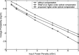 We also give the states of polarization (SOPs) variation of output optical signals on a Poincaré sphere without compensation and with first-order or the proposed higher-order PMD compensation in Fig. 3. Our aim is to qualify our proposed compensator’s capacity of reducing the PSP depolarization effects. The capacity is also an important quality for higher-order PMD compensators.2, 6 The bandwidth of simulated samples sweeps from supposing that . In order to keep the comparison fair and creditable, here the first-order compensator with adjustable DGD element3 just matches the fiber channel PMD at the carrier frequency, and the parameters setting of the proposed higher-order compensator is unchanged. We set the power splitting of the launched input SOP to be 0.5. Then first-order and higher-order PMD effects both lead to the pulse distortion. In Fig. 3, first-order and our proposed higher-order compensator can both work to improve the system performance. And our scheme is more effective to reduce depolarization effects caused by higher-order PMD effects. The SOPs of output signals compensated by the proposed compensation scheme (circles) nearly maintain the same place on the Poincaré sphere and this good result can be obtained from arbitrary optical fiber channel realization in our simulations. Fig. 3SOPs of output signals without compensation, with first-order compensator using adjustable DGD element,3 and with proposed higher-order compensator on Poincaré sphere. 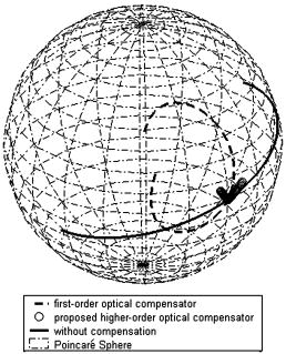 4.ConclusionsIn this paper, a new optical compensation scheme for higher-order PMD effects is proposed. The control algorithm for this compensation scheme is easier and more stable than the commonly used higher-order optical compensators. And a control method is advised to ensure the proposed scheme provides better performance than the first-order compensation. The efficiency is proved by numerical calculations. ReferencesH. Rosenfeldt,
“Deploying optical PMD compensators,”
Proc. Optical Fiber Commun. Conf.,
(2005) Google Scholar
I. Kaminow and
T. Li, Optical Fiber Telecommunications IVB, Academic Press, San Diego
(2002). Google Scholar
H. Sunnerud,
C. Xie,
M. Karlsson,
R. Samuelsson, and
P. A. Andrekson,
“A comparison between different PMD compensation techniques,”
J. Lightwave Technol., 20
(3), 368
–378
(2002). https://doi.org/10.1109/50.988985 0733-8724 Google Scholar
U. Neukirch,
“Time-resolved performance analysis of a second-order PMD compensator,”
J. Lightwave Technol., 22
(4), 1189
–1200
(2004). 0733-8724 Google Scholar
H. Koelnik,
L. E. Neison, and
J. P. Gordon,
“Emulation and inversion of polarization-mode dispersion,”
J. Lightwave Technol., 21
(2), 482
–495
(2003). https://doi.org/10.1109/JLT.2003.808764 0733-8724 Google Scholar
M. Shtaif,
A. Mecozzi,
M. Tur, and
J. A. Nagel,
“A compensator for the effects of high-order polarization mode dispersion in optical fibers,”
IEEE Photonics Technol. Lett., 12
(4), 434
–436
(2000). https://doi.org/10.1109/68.839043 1041-1135 Google Scholar
A. O. Dal Forno,
A. Paradisi,
R. Passy, and
J. P. von der Weid,
“Experiment and theoretical modeling of polarization-mode dispersion in single-mode fibers,”
IEEE Photonics Technol. Lett., 12
(3), 296
–298
(2000). https://doi.org/10.1109/68.826919 1041-1135 Google Scholar
H. Büllow,
“System outage probability due to first- and second-order PMD,”
IEEE Photonics Technol. Lett., 10
(5), 696
–698
(1998). https://doi.org/10.1109/68.669330 1041-1135 Google Scholar
G. Keiser, Optical Fiber Communications Third Edition, McGraw-Hill, New York
(2000). Google Scholar
|