|
|
|
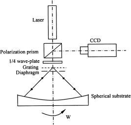
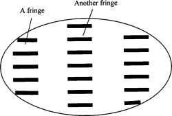
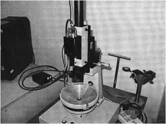
Metallic mesh is of increasing importance in electromagnetic interference windows,1 and the performance of inductive mesh is more excellent than other transparent conducting films in the infrared throughput and the electromagnetic attenuation.2, 3 Compared with planar mesh, curved mesh is much more extensively applied. As a special case of curved mesh, spherical mesh has a particular practical value. For fabricating an axial symmetrical mesh on the concave surface of a spherical substrate by a photolithography process, we need a noncontact alignment method that will avoid destroying the surface of photoresist and adjust the center of sphere to its spin axis. Thus, an alignment method that can adjust the center of a sphere to its spin axis is presented, and it can also be used for the fabrication of concave gratings and curved Fresnel-zone plates and the adjustment of lenses.4 As shown in Fig. 1, a laser beam passes through a polarization prism and a wave plate and is diffracted by an ordinary or phase grating that is fixed on the curvature center of a spherical substrate, and - and -order diffracted beams arrive at the substrate and return to the grating due to the obstruction of the diaphragm, and they are diffracted by the grating again. The -order diffracted beam of the former -order beam interferes with the -order diffracted beam of the former -order beam, and the coherent beam passes wave plate again and returns to the polarization prism. Because light passed through the wave plate twice, the polarization direction of the coherent beam is changed from the former laser beam. So the coherent beam can’t pass the polarization prism again and turns to a CCD detector, and an interference pattern is displayed on a screen (see Fig. 2). While the curvature center of the spherical substrate aligns with its spin axis, the interference pattern is still when the substrate is revolving about its spin axis (the two optical paths are same). Or else, while the curvature center of the spherical substrate deviates from its spin axis, the interference pattern will alter when the substrate is revolving about its spin axis (the two optical paths are different). Obviously, the fringe change scales of the interference pattern correspond with the error of alignment. In Fig. 3, O is the curvature center of the spherical substrate, is the position of grating, is the intersection point of the normal incidence light and the grating, is the intersection point of the reflected light and the grating, is the spin axis of the substrate, and is the alignment error of the center of spherical substrate and its spin axis. Given , , the refractive index , is the radius of the sphere, and is the single-pass error of the optical path for a beam. From Fig. 3, we see that and the equation of grating is5 In Eq. 2, is the period of the grating, is the angle of diffraction, is the order of diffraction, and is the wavelength. Thus, and (see Fig. 3). According to Eq. 1 and Eq. 2, and ignoring the term of , we haveIn Eq. 3, and , so the second term of Eq. 3 can be ignored:The total optical path difference is , and has the following relation with the fringe movement scale:In Eq. 5, is the value of the fringe movement distance divided by the fringe spacing, here called the fringe change scales.From Eq. 4 and Eq. 5, the relation of and can be obtained as According to Eq. 6, the precision of alignment is determined by the period of the grating. The smaller the period of the grating is, the higher the precision of alignment. But, the solution of Eq. 2 is nonexistent while . So the measurement precision of the alignment method is determined by the wavelength of the laser. Of course, the alignment error may be smaller than the laser wavelength.In Fig. 4, is the adjustment distance of the grating. From the three triangles of , , and , we can obtain In Eq. 7, is the angle of diffraction and is the radius of the sphere.Provided that , we have Provided that the substrate is immobile, the fringe spacing can be expressed byAccording to Eq. 2, we haveFrom Eq. 10, we know that the fringe spacing may be adjusted by moving the grating in a vertical direction.While the aligning error is one quarter of the grating’s period, the fringe change scale is one, so the eye’s smallest alignment error can be expressed as In Eq. (13), is the smallest change scale of the fringe and is the period of the grating. Provided that is half of the fringe spacing, we haveIn fact, while there are only two fringes on the screen, may be one-fifth of the fringe spacing or less, so the adjustment of fringe spacing is indispensable to a high precision alignment. While is , the error of the alignment method is less than , and even less than .The sensitive waveband of the selected photoresist is below , so a He–Ne laser is selected, with a wavelength of and an initial power of . The period of the selected phase grating is . The radius of the spherical substrate is , and its caliber is . The CCD imaging cell dimension is , and its minimal illumination is . Because the revolving error of spindle can’t be separated from the total error, an aerostatic bearing is used.6 The test shows that the spindle’s radial error and axial error are less than . First, the grating, diaphragm, and substrate are removed from the device, and a laser beam is directly reflected by the reflector that is fixed on the upper end face of the spindle. The alignment error of the laser beam and the spindle may be or less by observing the deviation of the reflected light (see Ref. 6). Afterward, we adjust the center of the sphere to its spin axis by the method, and the final alignment error is about 1.5 (the fringe change scale is about 1.5 fringe spacing), and the result is proved by an inductive micrometer dial that has a resolving ability of , i.e., the method may be verified by comparing it to the measurement result of the inductive micrometer dial on the same radial position of the substrate. Figure 5 is a photograph of the device. For fabricating symmetrical mesh on the concave surface of a spherical substrate, an alignment method that adjusts the center of the sphere to its spin axis is put forward. The device mainly consists of a laser, a polarization prism, a wave plate, a grating, and a CCD. It can realize submicron precision noncontact measurement, and fits for the lithography process. Furthermore, the alignment method may be also used for the fabrication of the concave grating and the curved Fresnel-zone plate, and even the adjustment of lens. Thus, the application of method will be extensive. ReferencesR. J. Noll,
“Some trade issues for EMI windows,”
Proc. SPIE, 2286 403
–410
(1994). 0277-786X Google Scholar
R. Urich,
“Far-infrared properties of metallic mesh and its complementary structure,”
Infrared Phys., 7 37
–57
(1967). https://doi.org/10.1016/0020-0891(67)90028-0 0020-0891 Google Scholar
X. G. Feng,
L. Fang, and
L. C. Sun,
“Characteristic dimension design and fabrication of metallic mesh,”
Opt. Precision Eng., 13
(1), 59
–64
(2005). Google Scholar
Y. Xie,
Z. Lu, and
F. Li,
“Fabrication of large diffracted optical elements in thick film on a concave lens surface,”
Opt. Express, 11 992
–995
(2003). 1094-4087 Google Scholar
J. Bahrmann,
K. R. Detring, and
G. Simonsohn,
“Frequency shifting of laser radiation by a moving grating,”
Opt. Commun., 22 365
–368
(1997). 0030-4018 Google Scholar
T. D. Milster and
C. L. Vernold,
“Technique for aligning optical and mechanical axes based on a rotating linear grating,”
Opt. Eng., 34 2840
–2844
(1995). 0091-3286 Google Scholar
|