|
|
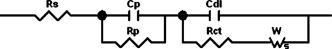
1.IntroductionThe classical research on electrochromic materials is focused mainly on solid devices in which glass is the transparent surface used as substrate. Recent investigations are focused on plastic substrates due to its flexibility, which will impel their applications as flexible displays and switchable optical filters. However, no industrially all-plastic electrochromic devices exists to date, due to a number of drawbacks such as low quality of the transparent conductor layer onto plastic substrates,1 among others. As a consequence of this trend, we have manufactured all-polymer flexible devices as described elsewhere.2, 3 In this work, we will focus on the electrical characterization of the devices, depending on their size. We will describe the impedance measurements carried out in them. The impedance measurement permits us to obtain important information for the modeling of the device. Electrical models should show the difference between the usual electrochromic devices and these ones, because the reduced number of layers should result in simpler electrical equivalent circuits than traditional EC ones. 2.Experimental ProcedureAs it has been described,2 electrochromic devices with a new configuration have been constructed (Fig. 1). This configuration avoids the use of a conductor layer to make a contact electrode. Instead, PEDOT acts as both the electrochromic layer and the electrode. PEDOT is colored in transparent-blue when oxidized and in dark-blue when reduced. We used poly(ethylene terephtalate) foils covered by PEDOT, commercialized by AGFA under the trademark of ORGACON. A tetrahydrofurane solution of a poly(ethylene oxide-lithium triflate) polymer electrolyte is deposited onto one of them by casting. Afterwards, the solvent is evaporated, at room temperature during 3 hours, and the second ORGACON EL is glued on top of the polymer electrolyte layer. In this configuration, one of the PEDOT layers acts as electrochromic material and the other layer acts as counterelectrode. The construction is totally symmetric; thus, the role of the PEDOT layers could be interchangeable. The easy construction of the devices, with only commercially available materials, simplifies from five to three the active layers number and may result in many technological advantages. Devices of different sizes were manufactured, and their electrical behavior has been tested. An impedance analyzer Model 4194A was used to derive the impedance characteristics of the devices. The whole system is controlled via HP-IB bus from a personal computer acquiring 401 points in each spectrum. Different DC bias voltage can be applied to the sample with an accuracy of . 3.Results and DiscussionImpedance spectroscopy measurements were carried out for the different devices tested. Fig. 2a for the increasing part of a ramp with steps, and Fig. 2b for the decreasing part of the cycle, both show the results for two EC devices with active areas of and , respectively. The steps are applied at a 60-s rate to ensure the switching conditions acquired in the transmittance measurements. Fig. 2Impedance modulus and phase plots for two devices with and active areas, during the application of potential steps of : from 0 to (a), and from 3 to (b). 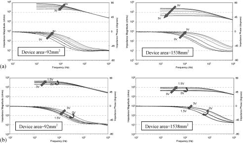 From the analysis of both figures, it can be seen that impedance is higher for the smaller device. Studying the impedance modulus, we can observe a mainly resistive behavior in low and medium frequencies. It stands for the mainly resistive role that the charge movement has in the reactions involved during the natural operation of the device, always at frequencies lower than . The value at low frequencies is changing with voltage, which corresponds to the changing electrochemical situation inside the device. In both devices, the impedance module is decreasing as the voltage increases. It shows that the active species have better conducting properties than the original ones and that the main current efficiency takes place at the beginning of the switching. Because of that, the consumption of the device should be reduced in normal operation, with the cell in the colored state, and with the application of short current pulses to maintain coloration (because this current will cross a less resistive material). For the decreasing part of the ramp (figures labeled as b), a change in the trend can be detected from to . This is also shown in chronoamperometric experiments. The signal should be applied during higher times to reach stochiometric equilibrium. At high frequencies, the behavior is not resistive, but its modulus is the same for all the voltages. According also to the phase plots, these features seem to be similar to those of a Randles cell, as suggested by Bell for this kind of devices.4 Nyquist plots of the smallest device are shown in Fig. 3. As it can be seen, at high frequencies [low Re(Z) values]-the linear trend is added to the resistance effect, constant for all the voltages, thus standing for the contacts of the device, and with a value of around . The different values of the low-frequency parts of the plots [high Re(Z) values] show the different resistances of the cell at changing voltages, from around to . The asymmetrical response in the two ramps is also detected in these plots (comparing Fig. 3a and 3b). These plots confirm a behavior that can be reasonably described by an equivalent circuit made by a Randles circuit with Warburg impedance simulating the ionic diffusion at low frequencies (Fig. 4). Table 1 shows the different elements that integrate the proposed electrical equivalent circuit. Additionally, this equivalent circuit may be useful to show some problems related to the homogeneity of the adhesive contact layers and the EC materials, not seen in the normal operation. This can be revealed by simulating the equivalent circuit through a resistance and capacitance in parallel configuration, which can serve as a feedback method to design appropriate materials with ionic and electronic properties to make devices durable over many cycles.5 Traditionally, organic ECs tended to suffer from problems with secondary reactions during switching affecting the stability and durability of these systems.6 The electrical analysis presented in this work may also contribute to develop more stable organic systems for switchable glazing applications, truck mirrors, among others. Fig. 3Nyquist plots for a device with of active area, while switching from 0 to (a) and from to (b). 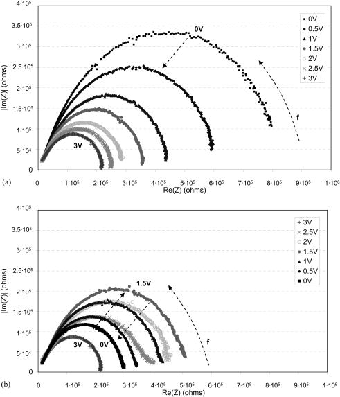 Table 1Components of the proposed electrical equivalent circuit for organic EC devices.
4.ConclusionsNew all-plastic electrochromic devices, constructed by usual techniques and with commercial materials, and with a configuration of five layers instead of the typical seven layers (PEDOT is contact and active layer), have been electrically characterized. Electrical characterization has been made in order to test their dynamical properties in operation. Charge injection shows that bleaching is slower and that a small current is driven to the cell with applied to maintain coloration. Impedance analysis and Nyquist plots can be used to derive the electrical parameters that may be useful to simulate the operation of the cell in a real polarization circuit. The device is supposed to act as an equivalent circuit made by a Randles circuit with Warburg impedance simulating the ionic diffusion at low frequencies. The simple behavior (compared with usual ones for electrochromic devices) detected here must be related to the simple symmetrical construction of the device, especially because of the reduced number of layers used. This work will enable better control of organic electrochromic devices, leading to improved electrooptical performance as well as a better understanding of the electrochemical charge injection process in these devices. The devices show promising results for electrically controlled window applications because switching time is not a critical parameter. Additionally, organic electrochromic devices can be used in truck mirrors, sunglasses, optical variable attenuators, displays, etc. In any case, polymerized ionic-liquids could improve the dynamic response of these devices. Further research on polymer electrolyte compositions and in the sticking or sealing processes will be done to improve the dynamic behavior of the EC devices. AcknowledgmentsWe thank Agfa, Daiso, and 3M for supplying free samples of materials. This work was partially supported by the Spanish Ministry of Science and Technology (grant no. PTR95-0940.01.OP). ReferencesD. S. Ginley and
C. Bright,
“Transparent conducting oxides,”
MRS Bull., 25 15
–18
(2000). 0883-7694 Google Scholar
D. Mecerreyes,
R. Marcilla,
E. Ochoteco,
H. Grande,
J. A. Pomposo,
R. Vergaz, and
J. M. Sánchez-Pena,
“A simplified all-polymer flexible electrochromic device,”
Electrochim. Acta, 49 35559
(2004). https://doi.org/10.1016/j.electacta.2004.03.032 0013-4686 Google Scholar
R. Vergaz,
J. M. S. Pena,
A. B. Gonzalo,
J. M. Ollero,
C. Vázquez,
J. A. Pomposo,
H. Grande, and
D. Mecerreyes,
“Characterization of novel all-plastic electrochromic devices: electro-optic and voltammetric response,”
Opt. Eng., 43
(12), 2975
(2004). https://doi.org/10.1117/1.1815333 0091-3286 Google Scholar
J. M. Bell,
J. P. Matthews, and
L. L. Skryabin,
“Modelling switching of electrochromic devices—a route to successful large area device design,”
Solid State Ionics, 152–153 853
–860
(2002). 0167-2738 Google Scholar
C. M. Lampert,
“Smart switchable glazing for solar energy and daylight control,”
Sol. Energy Mater. Sol. Cells, 52 207
–221
(1998). https://doi.org/10.1016/S0927-0248(97)00279-1 0927-0248 Google Scholar
C. M. Lampert and
C. G. Granqvist, Large-Area Chromogenics: Materials and Devices for Transmittance Control, Optical Engineering Press-SPIE, Bellingham, WA (1990). Google Scholar
|