|
|
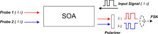
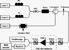
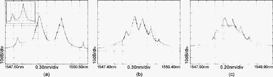
1.IntroductionRecently, various advanced optical modulation formats have been proposed and extensively investigated to enhance the transmission system performance. Among them, Frequency-shift keying (FSK) has been proven to have some advantages.1, 2, 3, 4, 5 It supports balanced detection scheme resulting in gain of optical signal noise ratio (OSNR) sensitivity and larger dispersion tolerance.1 FSK is very attractive for all-optical label processing.2, 3 Some passive optical network (PON) architectures also take advantage of high robustness to noise and Rayleigh backscattering reduction of FSK modulation, allowing intensity remodulation of one downstream without regeneration at the optical network unit (ONU).4, 5 In future advanced optical networks, several types of modulation formats, such as conventional amplitude-shift keying (ASK), differential phase-shift keying (DPSK), and FSK, would be used in different kinds of networks to optimize the performance. Thus, the optical modulation format conversion will be necessary in next-generation network routers or gateways. In this paper, we demonstrate an all-optical dual-wavelength conversion utilizing a cross-polarization modulation effect in a semiconductor optical amplifier (SOA) to realize simultaneous noninverted and inverted conversions with and power penalties, respectively. We also utilize this scheme for all-optical modulation format conversion from ASK to FSK for the first time to our knowledge by adjusting the power and frequency spacing of two converted signals. A clear advantage of this format converter is that the generated FSK tone spacing is easy to adjust because it is determined only by the frequencies of input probe lights. Another advantage is that the FSK can reach a very high bit rate at or above using this scheme. 2.PrinciplesThe schematic diagram is shown in Fig. 1. A signal beam and two probe beams are injected into an SOA simultaneously in a counterpropagation scheme. The intensity of the signal beam will modulate the SOA carrier density, which will induce different phase shifts to the transverse electric (TE) and transverse magnetic (TM) modes of the probe lights due to the SOA birefringence. Thus, the probe light polarization state will be modulated by the intensity of the input signal, which is called the cross-polarization modulation (CPM) effect. This polarization modulation of the probe beams is then converted to intensity modulation after a polarizer. The input polarization of the probe beams are adjusted by polarization controllers (PCs). In one case, the probe beam can pass through the polarizer when the input signal is in the OFF states; however, if the signal changes to the ON state, the CPM effect induces an obvious polarization rotation of the probe beam, and as a consequence, it is blocked by the polarizer. Thus, an inverted wavelength conversion is obtained. Conversely, by adjusting the input probe polarization, little probe can not pass through the polarizer with low signal power in, but if a relatively high signal power (ON state) is coupled, a polarization rotation leads to a higher intensity of the probe beam at the polarizer output. Thus, noninverted conversion is realized. In our scheme, the input polarization states of the two probe beams are properly adjusted to obtain simultaneous inverted and noninverted conversions such that the two converted data streams are exactly logically inverted. If the frequencies of the two probe beams are selected to be sufficiently close, the combination of the two converted beams can be regarded as an FSK signal, while the two probe frequencies form the two sideband components of the FSK. If we assume that the probe wavelength for noninverted conversion is while that for inverted conversion is , the ON state power of the noninverted and inverted signal after the polarizer can be written as Here, we use the superscripts and to refer to the ON and OFF states of the input signal. and are the probe power injected into and out of the SOA. and are the output polarization angles of and relative to the polarizer’s blocking axis, respectively. is the optical gain in SOA, and is the filtered spontaneous emission.Due to cross gain modulation (XGM) effect, the SOA gain with OFF-state input signal is greater than , and is also greater than . In order to generate an FSK signal with a constant optical power, should be equal to . According to Eqs. 1, 2, this can be achieved by adjusting the input power of the two probe beams and such that higher input power is needed for the noninverted probe beam . 3.Experimental Setup and ResultsThe experimental setup is shown in Fig. 2. The used SOA is a commercially available SOA by CIP Corp. The SOA bias current and temperature are maintained at and . The two probe beams are emitted from an Avanex laser module at (Laser 1) and a tunable laser made by HP Corp. (Laser 2). They are combined and launched into the SOA via an optical isolator. Two PCs are used to independently adjust the input probe polarization states. A third laser at (Laser 3) is modulated with the pseudo-random binary sequence at . The output nonreturn zero (NRZ) signal enters the SOA in the opposite side through a circulator. The output probe light is sent into a polarizer. In our experiment, the two probe frequencies are set close to generate an FSK signal, and we can use a filter with bandwidth to filter out the two converted signals together. Two cascaded tunable optical filters ( and ) as a frequency discriminator are used to filter out either one of the converted signals for FSK demodulation and evaluation. In order to experimentally adjust the system, the two output probe lights are first filtered out, respectively, after the cascaded filters. By adjusting the input probe polarization states via the PCs and observing the output waveforms, it is possible to obtain noninverted and inverted conversions at the two outputs, respectively. Then we filter out the two converted signals together via the first filter and adjust the input probe power to obtain a combined FSK signal with a constant optical power. In the experiment, we set one probe beam at for noninverted conversion and another at for inverted conversion. The wave forms of the input signal and two converted signals are shown in Fig. 3. Their eye diagrams are shown in the inset of Fig. 4. The input signal power is . In order to obtain two converted signals with the same intensity, the input probe power is carefully adjusted to be and for noninverted and inverted conversions, respectively. Noninverted conversion has higher input probe power, which agrees with the preceding theoretical analysis. The eye diagram of the FSK signal (the combined converted signals) in the inset of Fig. 4 indicates that it has nearly constant power. Fig. 3Measured wave forms for (a) input signal, (b) converted signal at , and (c) converted signal at . 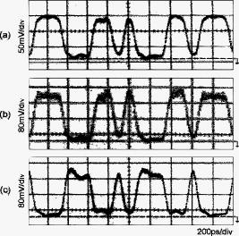 Fig. 4BER curves for noninverted and inverted wavelength conversions. Inset: Eye diagrams for (a) input signal, (b) noninverted converted signal, (c) inverted converted signal, and (d) FSK signal (the combined converted signals). 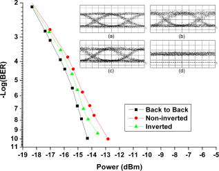 Figure 4 shows the bit error rate (BER) curves of the converted signals. The simultaneous noninverted and inverted conversions lead to power penalties of about and at a BER of , respectively. The higher penalty for noninverted conversion is mainly attributed to large relative intensity noise of the used probe source at . The optical spectrum of the FSK signal is shown in Fig. 5. In the preceeding experiment, the wavelength spacing of the two probe beams is set to , which is wide enough to enable easy FSK demodulation with two filters. The optical spectrum of demodulated FSK is shown in the inset of Fig. 5a. In our scheme, the FSK tone spacing can be adjusted by tuning the input probe wavelengths. Figures 5b and 5c show the generated FSK with tone spacing of and , respectively. In these spectra, four-wave mixing (FWM) contributions are found aside the converted signals, because of the deep saturation and high nonlinearity of SOA used. When the probe spacing is further reduced, the FWM effect is more severe, and its products may fall in the FSK band. In order to eliminate the FWM, the two input probes need to be orthogonally polarized.6 But in our scheme, the input polarization relationship between two probe lights is restricted by the value of signal-induced polarization rotation angle based on CPM, since the two probe lights should carry simultaneous noninverted and inverted signals after the same polarizer. In our experiment, the CPM-based polarization rotation is about measured by a polarization analyzer from General Photonics Corp., which is not large enough that the FWM effect is obvious. In fact, the rotation angle can be further increased by using a long SOA with specially designed waveguide structure to enhance the CPM effect; for example, a polarization rotation of has been achieved in Ref. 7. Then, the input two probe beams can be set nearly orthogonally polarized, and as a result, the FWM products in the sideband will be significantly suppressed. 4.ConclusionA novel method for an all-optical modulation format conversion from amplitude-shift keying to frequency-shift keying has been proposed and studied, by utilizing a dual-wavelength conversion based on cross-polarization modulation in an SOA. Experimental results at proved the feasibility of the proposed method. The proposed scheme can be used in optical network routers to provide simultaneous wavelength conversion and modulation format conversion functions. AcknowledgmentsThis work was supported by the National Natural Science Foundation of China (Grant No. 60520130298). ReferencesW. Idler,
A. Klekamp,
R. Dischler, and
B. Wedding,
“Advantages of frequency shift keying in systems,”
Proc. IEEE LEOS 2004 Workshop on Advanced Modulation Formats, 51
–52
(2004) Google Scholar
J. Zhang,
N. Chi,
P. V. Holm-Nielsen,
C. Peucheret, and
P. Jeppesen,
“An optical FSK transmitter based on an integrated DFB laser-EA modulator and its application in optical labeling,”
IEEE Photonics Technol. Lett., 15
(7), 984
–986
(2003). https://doi.org/10.1109/LPT.2003.813415 1041-1135 Google Scholar
E. N. Lallas,
N. Skarmoutsos, and
D. Syvridis,
“An optical FSK-based label coding technique for the realization of the all-optical label swapping,”
IEEE Photonics Technol. Lett., 14
(10), 1472
–1474
(2002). https://doi.org/10.1109/LPT.2002.801825 1041-1135 Google Scholar
I. Garces,
J. C. Aguado,
J. J. Martinez,
A. Lopez,
A. Villafranca, and
M. A. Losada,
“Analysis of narrow-FSK downstream modulation in colorless WDM PONs,”
Electron. Lett., 43
(8), 471
–472
(2007). https://doi.org/10.1049/el:20073908 0013-5194 Google Scholar
C. Arellano,
V. Polo,
C. Bock, and
J. Prat,
“Bidirectional single fiber transmission based on a RSOA ONU for FTTH using FSK-IM modulation format,”
3
–4
(2005). Google Scholar
R. Paiella,
G. Hunziker,
U. Koren, and
K. J. Vahala,
“Polarization-dependent optical nonlinearities of multiquantum-well laser amplifiers studied by four-wave mixing,”
IEEE J. Sel. Top. Quantum Electron., 3
(2), 529
–540
(1997). https://doi.org/10.1109/2944.605704 1077-260X Google Scholar
H. Soto,
E. Alvarez,
C. A. Diaz,
J. Topomondzo,
D. Erasme,
L. Schares,
L. Occhi,
G. Guekos, and
M. Castro,
“Design of an all-optical NOT XOR gate based on cross-polarization modulation in a semiconductor optical amplifier,”
Opt. Commun., 237
(1), 121
–131
(2004). 0030-4018 Google Scholar
|