
|
|
|
Computer-generated holograms (CGHs) for encoding arbitrary complex transmittances, with electrically addressable spatial light modulators (SLMs), have been developed during the last decade. Because of their high efficiency, CGHs based on phase SLMs are specially appreciated.1, 2, 3 These CGHs can be accurately implemented only by using a perfect phase SLM providing phase modulation of . Unfortunately, commercial twisted-nematic liquid-crystal (TNLC) SLMs, in usual configurations, only provide a poor approximation to the phase modulation (referred to as phase-mostly modulation). Davis proposed a special arrangement with a TNLC-SLM, with an improved phase-mostly modulation.4 A drawback of this proposal is the necessity of employing an operating wavelength on the order of 450 nm (or less), and two high-quality retardation plates in addition to a couple of linear polarizers. Here we generalize the holographic code reported in Ref. 2, in order to enable its implementation with the conventional configuration of a TNLC-SLM, employing two polarizers and a He-Ne laser. Essentially, the CGH discussed in Ref. 2 is based on the Fourier expansion with in the open phase interval and coefficients . Functions and (and other functions employed here) are dependent on the spatial coordinates , but for brevity they will be written without such coordinates, in most cases. By computing the phase attenuation from the relation , the term in Eq. 1 becomes identical to the complex function . Under this condition, the function , on the left side in Eq. 1, represents a CGH that encodes the arbitrary complex modulation , with error modulation given by the rightmost term in Eq. 1. In this code, the domain for both the amplitude and the function is the interval [0,1], and the CGH phase, , takes values in the interval .Our purpose is to consider a modified CGH transmittance where denotes a positive definite amplitude, coupled with the phase modulation . Assuming that takes values in the interval , where , the restricted phase domain for the modified CGH is . The aim is to implement this CGH with the modulation provided by a TNLC-SLM, in a simple configuration, employing two polarizers and a He-Ne laser. A modulation of this type, depicted in the polar plot of Fig. 1, was experimentally obtained for the TNLC-SLM “LC2000” of HoloEye Photonics AG. In this plot, amplitude and phase are respectively represented by the radial and azimuthal coordinates. The polarizers at the input and output of the SLM were oriented at angles and , respectively, measured from the director axis at the SLM input plane. For this modulation, the phase domain is , with , and the normalized amplitude takes values from 0.72 to 1. The maximum amplitude occurs at the extremes, , of the phase domain.Fig. 1Polar plot for the experimental phase-mostly modulation of a TNLC-SLM. Radial and angular coordinates represent respectively the amplitude and phase modulations. 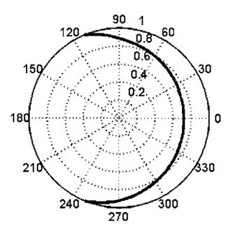 To obtain the signal-noise relation in the modified CGH we multiply each term in Eq. 1 by the amplitude modulation , obtaining The condition transforms the first term on the right side of Eq. 3 into the complex signal . Unfortunately for a phase-mostly modulation, as the one shown in Fig. 1, this condition cannot be fulfilled for values of close to 1, because and . This difficulty is overcome if is computed using the new restrictionfor an appropriate constant smaller than 1. In this case, the new relation between the CGH and the signal is , with modulation error given by the rightmost term in Eq. 3. For maximum CGH efficiency, we must find the maximum value of , making it possible to fulfill Eq. 4. For modulations similar to that in Fig. 1, we have found that must be chosen as the minimum value between the SLM constants and . For the modulation in Fig. 1, we obtained .For separation of noise from signal in the CGH, the signal phase is substituted [in Eq. 3] by a new phase , where is either a linear or a quadratic phase carrier.2 According to Eq. 3, a CGH designed with the quadratic phase carrier [ , with ], which is illuminated by a plane wave, generates on-axis the Fourier transform of the complex signal at the distance from the CGH plane, without necessity of a Fourier transforming lens. The Fourier transform of the ’th error modulation term is formed at a distance from the CGH. The more significant term, , in the error modulation expansion in Eq. 3 (corresponding to the zero order, ) presents a flat phase modulation, and shows only a marginal contribution to the noise (by free propagation without focusing) at the signal plane. We have found that the signal-to-noise ratio (SNR), at the signal Fourier spectrum plane , is acceptable if the envelope of the signal amplitude is not highly attenuated in the signal domain. In this case, the values for in Eq. 4 tend to be closer to 1, and the main error contribution tends to be low. Next, we describe two CGHs, designed for the modulation in Fig. 1, which illustrates the last assertion. We implemented experimentally two modified CGHs [of the type represented in Eq. 2], for the coupled amplitude-phase modulation plotted in Fig. 1. The first CGH encoded the complex function , within a circular support covering 14 rings of the Bessel function . In the transmittance is a normalization constant, is a radial spatial frequency, is the focal distance of the quadratic phase carrier, and . The second CGH encoded the transmittance , where is a phase grating, designed with an iterative Fourier transform algorithm,5 to generate an array of uniform diffraction orders. The phase distribution in a period of the grating is shown in Fig. 2a. The employed SLM (with ) was able to display a CGH for an array of periods of this grating. Considering the pixel pitch of the SLM to avoid undersampling of the phase modulation in the CGHs, we employed a phase carrier with focal distance . According to the discussion in previous paragraph, the planes at the distance from the CGHs (illuminated by a plane wave) present the Fourier spectra of the complex signals and , respectively. Fig. 2(a) A single period of the phase modulation of grating generating uniform diffraction orders and (b) array of diffraction orders recorded at the distance from the CGH encoding the transmittance . 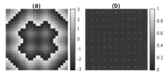 The amplitude and phase of the first CGH are depicted in Figs. 3a, 3b. To evaluate the performance of this CGH, we computed the Fresnel field at a distance from the transmittance , whose intensity is shown in Fig. 3c. On the other hand, the experimentally recorded intensity at a distance from the CGH is shown in Fig. 3d. As can be noted, the experimentally generated ring-shaped field is quite similar to the one obtained by numerical simulation for the encoded signal. The measured uniformity error in the experimental annular field is close to 5%. The experimentally recorded field at the distance from the second CGH is shown in Fig. 2b. In order to visualize both signal and noise, this image displays the square root of the recorded intensity. The luminous powers at the signal spots presented a standard deviation, normalized with the average spot power, approximated to 4.4%. Fig. 3(a) Amplitude and (b) phase of a CGH that encodes the transmittance , (c) intensity pattern at the distance from the transmittance , and (d) intensity pattern recorded at the distance from the CGH. 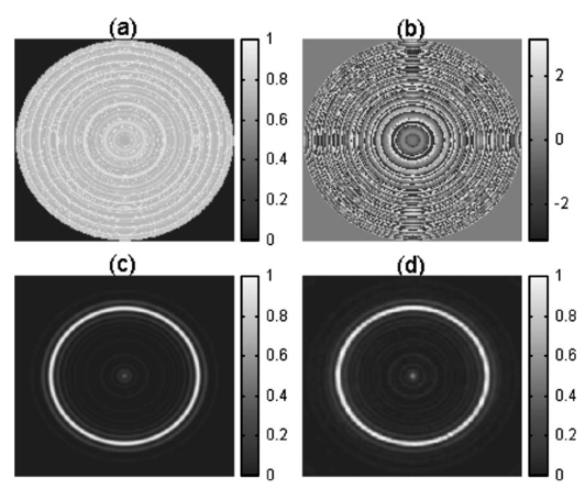 In summary, we discussed a CGH that can be implemented with the phase-mostly modulation provided by a TNLC-SLM, using only two polarizers and a He-Ne laser. When the envelope of the amplitude of the encoded signal field is not highly attenuated in the domain of this field, the signal self-reconstruction, at the focal plane of the quadratic phase carrier, is quite satisfactory. This result is illustrated for two experimentally implemented CGHs. ReferencesR. W. Cohn and
M. Liang,
“Approximating fully complex spatial modulation with pseudorandom phase-only modulation,”
Appl. Opt., 33 4406
–4415
(1994). 0003-6935 Google Scholar
J. A. Davis,
D. M. Cottrell,
J. Campos,
M. J. Yzuel, and
I. Moreno,
“Encoding amplitude information onto phase-only filters,”
Appl. Opt., 38 5004
–5013
(1999). 0003-6935 Google Scholar
V. Arrizón,
“Optimum on-axis computer-generated hologram encoded into low-resolution phase-modulation devices,”
Opt. Lett., 28 2521
–2523
(2003). 0146-9592 Google Scholar
J. A. Davis,
I. Moreno, and
P. Tsai,
“Polarization eigenstates for twisted-nematic liquid-crystal displays,”
Appl. Opt., 37 937
–945
(1998). 0003-6935 Google Scholar
V. Arrizón,
M. Testorf,
S. Sinzinger, and
J Jahns,,
“Iterative optimization of phase-only diffractive optical elements based on a lenslet array,”
J. Opt. Soc. Am. A, 12 2157
–2164
(2000). 0740-3232 Google Scholar
|


