|
|
|
The quality of the radiated sound of a musical instrument depends mostly on the structural vibrations of its resonator. Since the structural vibrations manifest themselves primarily through the surface vibrations, these have been studied applying numerical modeling and diverse experimental techniques.1 A known numerical method for calculating vibrational modes is finite element analysis.2 The experimental approaches include pointwise methods such as those using accelerometers3 and full-field methods such as time-averaged holographic interferometry4 and electronic speckle pattern interferometry.5 However, these experimental techniques are time and means consuming since they use on one hand complicated procedures and on the other hand expensive equipment such as special monochrome CCD cameras or high-quality optical elements. We propose a new device for surface vibration measurements that is simple, fast, and inexpensive, yet provides full-field and non-contact measurements. Our approach is based on using a quasi-Fourier digital holography setup with commercial inexpensive elements such as a color digital camera and large plane mirrors. In digital holography with a quasi-Fourier setup,6, 7 both a reference point source and an object are placed at the input plane and an array photodetector at the hologram plane. Thus, digital holograms are recorded optically and stored in computer memory as image files of primary interference fringes. Two symmetrical hologram reconstructions are obtained numerically by calculating the Fourier transform of the recorded data. If we denote the dynamic object wave front with and the position of the point source with , then the input can be described as: . If only out-of-plane harmonic vibrations of the object surface occur and the illumination is normal to the surface, then , where denotes the static object wave front, the vibration amplitude, the wavelength, and the vibration frequency. The diffracted field at a distance from the input plane can be calculated according to Fresnel approximation as: where denotes the Fourier transform operation, the spatial frequencies, and where the constant terms are omitted. The exposure is obtained by integrating the instantaneous intensity , i.e., , where is the exposure time. For the integration time , one of the additive exposure terms is in the form:8 yielding for the reconstruction (modulus of the inverse FT):In Eqs. 2, 3, is the zero-order Bessel function of the first kind. The Bessel function shows that the object reconstructions are covered with the modulation fringes. The number and distribution of fringes depend on the amplitude , which is generally a function of spatial coordinates and the frequency at which the investigated surface is vibrating, i.e., . Therefore, the hologram reconstruction reveals the main characteristics of the vibration mode: the node structure and vibration amplitudes. In the case of vibrating surfaces of most musical instruments, detection of very regular fringe patterns is expected due to the symmetry of their resonant bodies. For example, irregularities in fringe patterns of percussion instruments indicate detuning of their membranes.We constructed an experimental device shown schematically in Fig. 1. It is composed of a laser, a variable beam splitter, a beam collimator, an array sensor, and various lenses and mirrors. We used a He–Ne laser as a light source and a color digital camera (Olympus E-1, objective lens removed, sensor: of a size , primary RGB filter) as an array photodetector. The beam emerging from the laser is split into an object and a reference beam. The reference beam is first expanded and collimated, then focused in the plane of the object surface, and finally steered by mirrors onto the detector. The object beam is expanded for uniform illumination of the vibrating surface and then directed to the detector. To excite the surface externally, we used a loudspeaker with a sound whose form, frequency, and intensity are controlled by a computer. To shorten the total length of the device, we placed two large inexpensive plane mirrors (size: ) between the object and the sensor. Thus, digital holograms are recorded at a distance of from the object, using the exposure time of and the beam intensity ratio (reference vs. object) between 2.5 and 3.5. Fig. 1Scheme of the experimental setup: VBS—variable beam splitter, M—mirror, —large mirror, COL—collimator, L—lens, VS—vibration surface, LS—loudspeaker, DC—digital camera, PC—personal computer, and Ob—object. 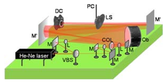 Each hologram reconstruction is obtained by the following procedure:
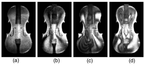
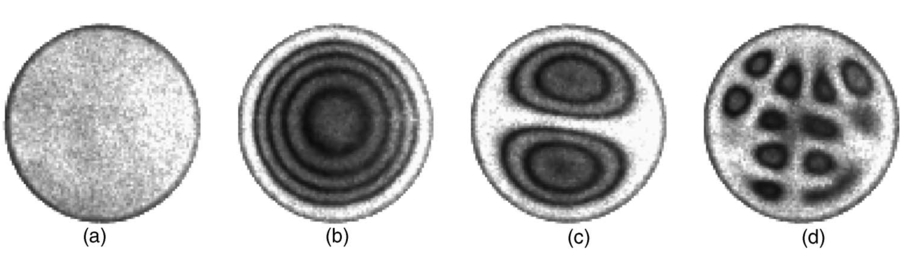
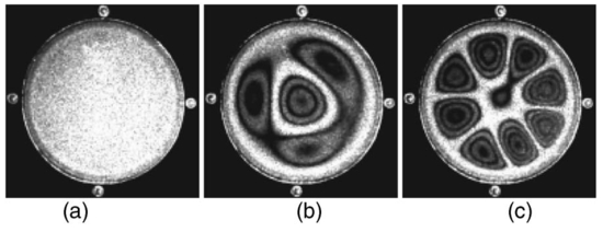
Figures 2, 3, 4 demonstrate the experimental results for two types of musical instruments: one type with a string (a violin, Fig. 2) and the other type with a circular membrane (a dumbek, Fig. 3, and a tunable drum, Fig. 4). Each figure shows a static hologram reconstruction plus the fringe patterns of typical vibration modes at several frequencies. Figure 5 demonstrates the sensitivity of the method for tuning the drum. The musical instruments with a membrane are tunable insofar as the membrane tension may be adjusted. For an ideal membrane, the accuracy of the tuning is defined by applying identical tension to each lug. The tuning of our drum involves adjusting the tension at four points around its circumference. Figure 5a shows symmetrical fringe pattern at the frequency of . By turning only the left lug in steps of quarter turns, we obtained the asymmetrical fringe patterns, as shown in Figs. 5b, 5c, 5d. By repeating the tuning tests at various frequencies, we observed that the higher frequencies have shown higher tuning sensitivities. That conclusion follows also from the results of the non-tunable instrument. As evident from Fig. 3, while the fringe patterns appear symmetrical at the low frequencies ( and ), it is apparently asymmetrical at a higher frequency . Fig. 5Hologram reconstructions for tunning the drum at : (a) zero state, (b) quarter turn, (c) half turn, and (d)three-quarter turn. 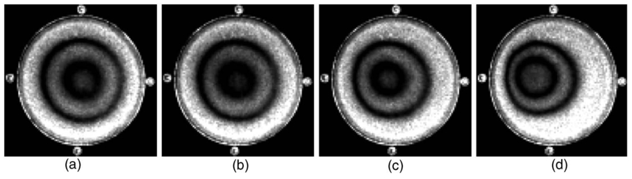 In conclusion, an inexpensive experimental device for measuring the surface vibrations of musical instruments is reported. The presented results demonstrate the quality of the obtained information about vibration modes and tuning properties of musical instruments. Based on the quasi-Fourier digital holography setup, the proposed device uses an original architecture compacted with large mirrors and equipped with a commercial color digital camera as an array detector. We have been using two large mirrors, although following the same principle more mirrors can be added to shorten the total length of the device. The noticeable effect of these inexpensive mirrors was the appearance of the additional fringes of the spatial frequency one order lower than the spatial frequency of the primary interference fringes. However, the quality of the hologram reconstructions was not influenced by these additional fringes. Similarly, the quality of holograms captured by the color digital camera and transformed to gray-scale images was comparable to the quality of holograms captured by a professional monochrome CCD camera regularly used in digital holography. Finally, it is worth noting that an inexpensive commercial device can be constructed for measuring the surface vibrations of a wide class of objects using the principle introduced in this work. AcknowledgmentThis work was supported by the Croatian Ministry of Science, Education and Sports under the project no. 0035005. ReferencesN. H. Fletcher and
T. D. Rossing, The Physics of Musical Instruments, Springer-Verlag, New York (1998). Google Scholar
N. F. Rieger,
“The relationship between finite element analysis and modal analysis,”
Sound Vib., 20 20
–31
(1986). 0038-1810 Google Scholar
K. D. Marshall,
“Modal analysis of a violin,”
J. Acoust. Soc. Am., 77 695
–709
(1985). 0001-4966 Google Scholar
W. Reinecke and
L. Cremer,
“Application of holographic interferometry to vibrations of the bodies of string instruments,”
J. Opt. Soc. Am., 48 988
–992
(1970). 0030-3941 Google Scholar
O. J. Lokberg,
“ESPI—The ultimate holographic tool for vibration analysis?,”
J. Acoust. Soc. Am., 75 1783
–1791
(1984). 0001-4966 Google Scholar
N. Demoli,
J. Meštrović, and
M. Sović,
“Subtraction digital holography,”
Appl. Opt., 42
(5), 798
–804
(2003). https://doi.org/10.1038/nature02053 0003-6935 Google Scholar
N. Demoli,
D. Vukicevic, and
M. Torzynski,
“Dynamic digital holographic interferometry with three wavelengths,”
Opt. Express, 11
(7), 767
–774
(2003). 1094-4087 Google Scholar
N. Demoli and
D. Vukicevic,
“Detection of hidden stationary deformations of vibrating surfaces by use of time-averaged digital holographic interferometry,”
Opt. Lett., 29
(20), 2423
–2425
(2004). https://doi.org/10.1364/OL.29.002423 0146-9592 Google Scholar
|