|
|
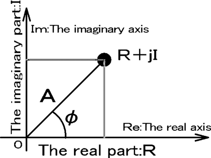
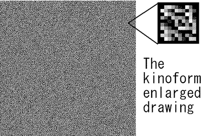
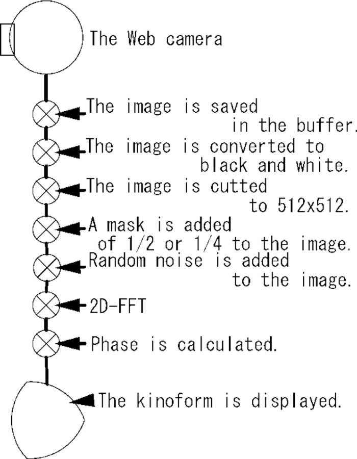
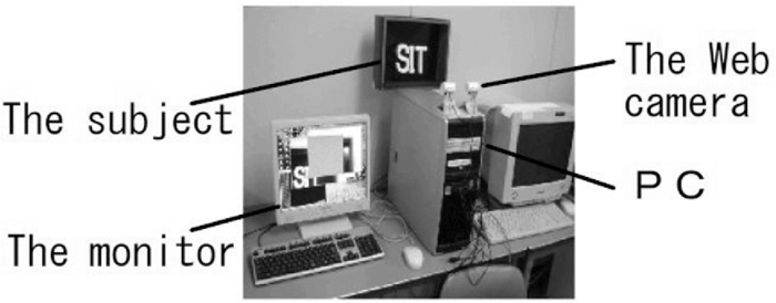
1.IntroductionWe aimed to develop a system that uses a single personal computer to create a real-time interference fringe. This system makes the real-time animation of a real three-dimensional (3D) object with an inexpensive web camera through use of a simple kinoform-type pattern. Approximately 10 frames of the 30 frames/s recorded by the web camera were used to create the kinoform of the real-time animation that a kinoform-type pattern is computed for each frame of a movie. A kinoform allows for the high-speed processing of a significant amount of data (e.g., 262,144 elements in a 512×512 matrix); the fact that this processing methodology allows for the reconstruction of an image using neutral colors is unique because it enables the computation of an interference fringe at very high speeds by calculating the two-dimensional fast Fourier transform (2D-FFT) with a personal computer.1 Other methods used to increase the calculation speed with which a computer-generated hologram (CGH) is able to create a table have been reviewed previously.2 Recently, there has been increasing interest in the use of a graphics processing unit (GPU) or a custom large scale integration3, 4, 5, 6, 7, 8 to perform general computations, such as an FFT, due to the higher throughput capacity of these devices. Current methods do not utilize the increased speed of the GPU for the general computation of the 2D-FFT using a kinoform, resulting in the need for multiple calculations. The method described here compares the kinoform creation processing time when using a CPU versus the time used by a GPU. In addition, we review the features that are promising for real-time processing that allows for the recording of an animation of a real 3D object using an inexpensive web camera. 2.KinoformOur method uses an FFT when synthesizing a CGH. The real part (Rxy) of the complex amplitude distribution (Txy) of the computed wavefront (which should record an imaginary part, Ixy) is indicated in Fig. 1. The wavefront amplitude Axy and phase φxy are given by formulas 1, 2 below. Amplitude Eq. 1[TeX:] \documentclass[12pt]{minimal}\begin{document}\begin{equation} {\rm A}_{{\rm xy}} = \sqrt {{\rm R}_{{\rm xy}}^2 + {\rm I}_{{\rm xy}}^2 }, \end{equation}\end{document}*Axy of Formula 1 is about constant. Eq. 2[TeX:] \documentclass[12pt]{minimal}\begin{document}\begin{equation} {\rm Phase}\ \varphi _{{\rm xy}} = \tan ^{ - 1} \frac{{{\rm I}_{{\rm xy}} }}{{{\rm R}_{{\rm xy}} }}. \end{equation}\end{document}These formulas assume that the wavefront amplitude Axy is constant, which is caused by the random noise, and it reconstructs an image only from the information provided by the phase (φxy). The phase value (φxy) is distributed on the kinoform surface in 256 levels; this phase modulation is imparted to the liquid crystals using a voltage change (Fig. 2). In addition, optical phase modulation is also possible. 3.MethodsOur method depends on the kinoform, which uses a method to create the CGH for the optical reconstruction that relies on a twisted-nematic (TN)-type LCD. As indicated in Fig. 3, the process begins by recording an animation of the real 3D object with a web camera. The animation is converted to black and white, then begins to finish cutting off a 512×256 portion of the original image to create the 512×512 kinoform with 2D-FFT. It avoids the issue in which the real images and conjugate images (composing the reconstructed image) begin to pile up; it shifts the image to the 512×512 square half in the CPU and GPU methods. The GPU was programmed using compute unified device architecture (CUDA), which is provided by NVIDIA, Inc..3, 4 The GPU used for this study was the GeForce 8800 GTX, which has 128 integration shaders that operate in parallel and allows for 345.6-GFLOPS single-precision operation at peak performance. Method (a) When using CUDA to create the kinoform from the 2D-FFT (if using the CUFFT library that depends on CUDA), the FFT can be simply and quickly executed on the GPU. The GPU uses the CUFFT library function cufftExecC2C to compute the FFT. Therefore, it is not necessary to tabulate sine or cosine values to perform the 2D-FFT with CUDA. Method (c) or (d) of after relies on a CPU to process the table of the random noise (e.g., a 512×512 matrix) (or function into the direct of random noise processing) in addition to the GPU processing. Method (b) As indicated in Table 1, along with formulas 3, 4, the sine or cosine values are computed beforehand and then arranged to be used by the CPU during the FFT calculation to compute the CGH, and Method (c) or (d) rely on a CPU to process the table of the random noise (e.g., a 512×512 matrix) (or function into the direct of random noise processing). Eq. 3[TeX:] \documentclass[12pt]{minimal}\begin{document}\begin{equation} \begin{array}{l} { \langle {\rm Real part} \rangle } \\[5pt] {T\cos [{\rm it}][k] = \cos (k \times \pi /xp^2),} \\ \end{array} \end{equation}\end{document}Eq. 4[TeX:] \documentclass[12pt]{minimal}\begin{document}\begin{equation} \begin{array}{l} { \langle {\rm Imaginary part} \rangle } \\[5pt] {T\sin [{\rm it}][k] = \sin (k \times \pi /xp^2),} \\ \end{array} \end{equation}\end{document}Eq. 5[TeX:] \documentclass[12pt]{minimal}\begin{document}\begin{equation} {\rm Rand}_{xy} = [{\rm random numbers}], \end{equation}\end{document}Eq. 6[TeX:] \documentclass[12pt]{minimal}\begin{document}\begin{equation} \begin{array}{l} { \langle {\rm Real part} \rangle } \\[3pt] {{\rm Are}_{xy} = b_{xy} \times \exp (0.0) \times \cos (2\pi \times {\rm Rand}_{xy})_{xy},} \\ \end{array} \end{equation}\end{document}Eq. 7[TeX:] \documentclass[12pt]{minimal}\begin{document}\begin{equation} \begin{array}{l} { \langle {\rm Imaginary part} \rangle } \\[3pt] {{\rm Aim}_{xy} = b_{xy} \times \exp (0.0) \times \sin (2\pi \times {\rm Rand}_{xy})_{xy}.} \\ \end{array} \end{equation}\end{document}Table 1The variable distribution used in the FFT to create the 512×512-element kinoform.
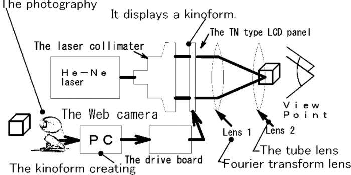
4.ResultsAs indicated in Figs. 4, 5, the program was created using Visual C++ (Visual Studio 2008 Professional Edition C++) and CUDA (NVIDIA CUDA, version 2.1) with a single personal computer (Table 2) and one web camera (Table 3). These figures illustrate the creation of the kinoform presented in Fig. 2. As indicated in Figs. 4 and 6 using a TN-type LCD (Table 4), the system uses a He–Ne laser (632-nm wavelength) and a laser collimator acquired from Neo Arc Co. Ltd. This system performs a Fourier transformation of the kinoform with lens 1, and the image formation can be visualized with lens 2. The reconstructed image can be observed with two eyes, as illustrated in Fig. 7. The black and white pictures shown in Fig. 7 recorded the animation at 10.3 fps. Fig. 7The real-time kinoform reconstructed image: (a) the real 3D object image of the camera captures the video (the real 3D object is a sign), and (b) a video of the reconstructed image. (QuickTime, 1.1 MB) 10.1117/1.3596384.1 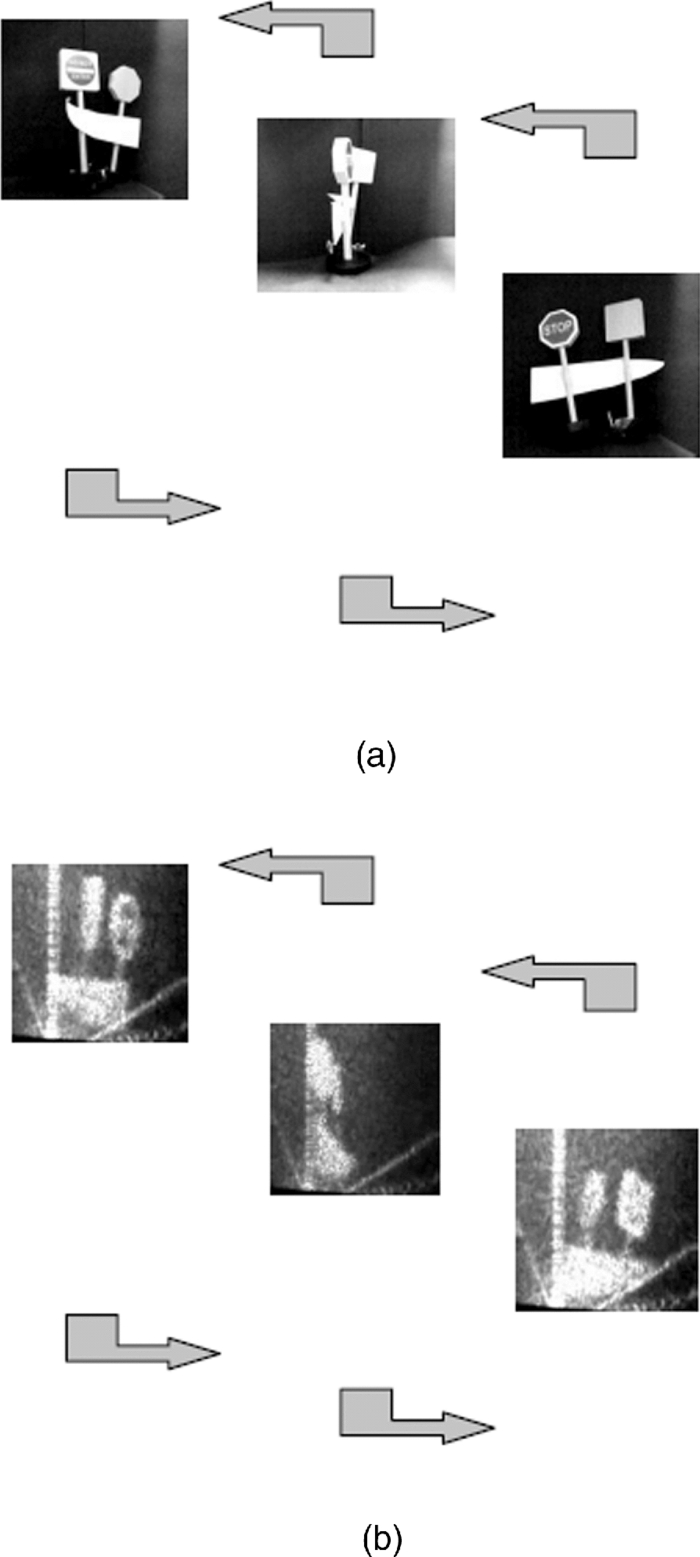 Table 2Specifications of the personal computer.
Table 3Specifications of the web camera.
Table 4Specifications of the TN-type LCD.
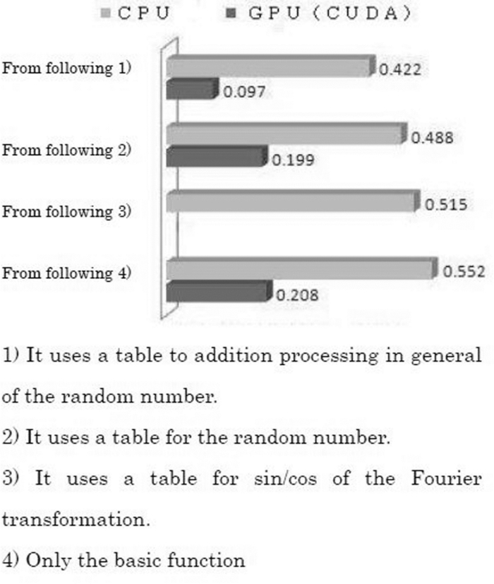
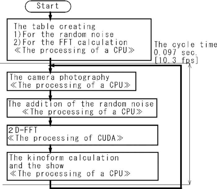
5.DiscussionThe cycle time required by the CPU and GPU, the images recorded by the web camera, the 2D-FFT processing, and the kinoform are all diagrammed in Fig. 9; these were measured using the C++ time library. The cycle time required for each step is indicated in Fig. 8. The results indicated that the operation times increase in the following order: GPU (table) < GPU < CPU (table) < CPU (C++). According to these results, the GPU requires less than or equal to 1/4 the operation time of the CPU. Therefore, use of a GPU is ideal for rapid kinoform creation. Because web camera imaging is buffered during animation, the operation time depends mostly on the 2D-FFT and a few other influences. This was independent of the processing that was required for the kinoform created by the 2D-FFT. The operation time increases by about 0.01 s due to the photography of the web camera if the operation time includes the showing of the image. A big portion of the time load arises from the change of the operation time of Fig. 8 to the CPU during the time required to begin addition of the data of the random number by becoming a table. As indicated in Fig. 9, there was a large difference between the results in the cases of use of the CPU only and the cases with the addition of the GPU. The result of calculation of only the 2D FFT by the GPU yielded an interesting result. It was observed that the majority of the increase in speed of the kinoform creation process was due to an increase in 2D-FFT speed. 6.ConclusionThe superior performance of the GPU relative to the CPU resulted in a more rapid computation. The real-time processing of images of a real 3D object taken by a web camera using a kinoform-type CGH processing methodology is a technique that can be sped up using general purpose GPU technology. Using a GPU also meant using CUDA, which was provided by NVIDIA, Inc. The source code for C was developed using Microsoft Corporation's Visual Studio in the Windows environment. Future research should be able to leverage this work. In future work, the use of multiple GPUs will be explored to further speed up real-time kinoform processing. AcknowledgmentsThe authors wish to express their gratitude to Dr. K. Takano, Dr. M. Ohki, and Dr. K. Sato for their assistance in providing guidance with regard to conference presentations and research in general. In addition, the authors are grateful to all members of the laboratory of Dr. K. Sato who cooperated in this study. ReferencesK. Sato, M. Tozuka, K. Kiuchi,
“Characteristics of Kinoform by plural LCD panels and its application to display the color image,”
J. Inst. Image Inf. Telev. Eng., 29 331
–332
(1993). Google Scholar
T. Yatagai,
“The spread of the computer-generated hologram technology,”
(2009) http://optlab2.bk.tsukuba.ac.jp/jp/people/yatagai/Lectures/WWW-CGH.htm Google Scholar
T. Shimobaba and T. Ito,
“Applying the parallel processing technology sophisticated in graphics processing field to general purpose numerical computing: The fact of GPU (graphics processing unit) computing using the CUDA technology,”
(2008) Google Scholar
T. Shimobaba and T. Ito,
“High performance computation of optical wave propagation (Fresnel diffraction) using FFT on GPU: The fact of GPU (graphics processing unit) computing using the CUDA technology (2),”
(2008) Google Scholar
T. Mizukami, Y. Ichihashi, T. Shimobaba, H. Nakayama, A. Shiraki, N. Masuda, T. Ito,
“One-Unit System for Electroholography Using a Special-Purpose Computer with a High-Resolution Liquid Crystal Display,”
J. Inst. Image Inf. Telev. Eng., 62
(11), 1874
–1876
(2008). Google Scholar
O. Nishikawa, T. Okada, K. Matsumoto, T. Ito, M. Taiji, H. Yoshikawa, and T. Honda,
“Exclusive LSI For Calculation of Fresnel Hologram,”
J. Inst. Image Inf. Telev. Eng., 32 96
–97
(1996). Google Scholar
S. Matsuda, T. Fujii, T. Yamaguchi, and H. Yoshikawa,
“Fast Generation of Computer-Generated Disc Hologram by Graphics Processing Unit,”
IEICE, 108
(425), 223
–227
(2009). Google Scholar
H. Yoshikawa,
“Computational speed of Fresnel holograms,”
IEICE, 241
(1994). Google Scholar
Biography
|
||||||||||||||||||||||||||||||||||||||||||||||||||||||||||||||||||||||||||||||||||||||||||||||||||||