|
|
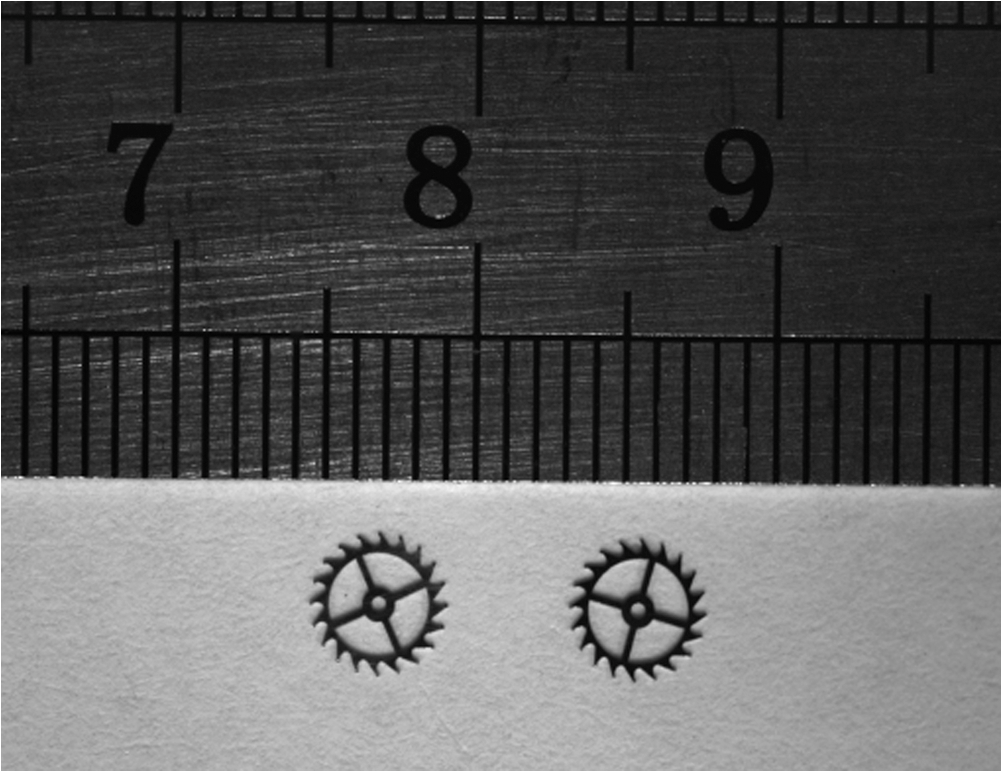
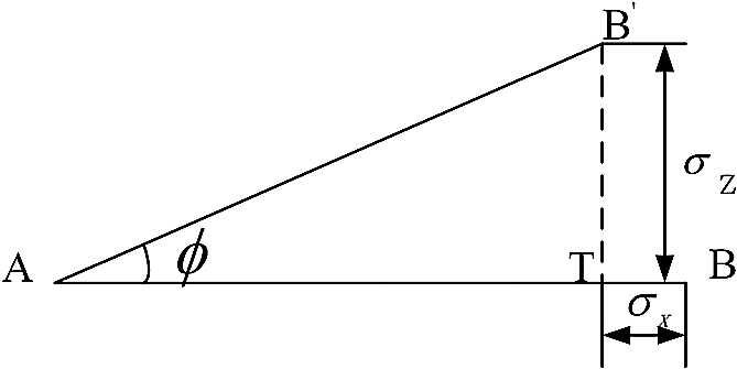
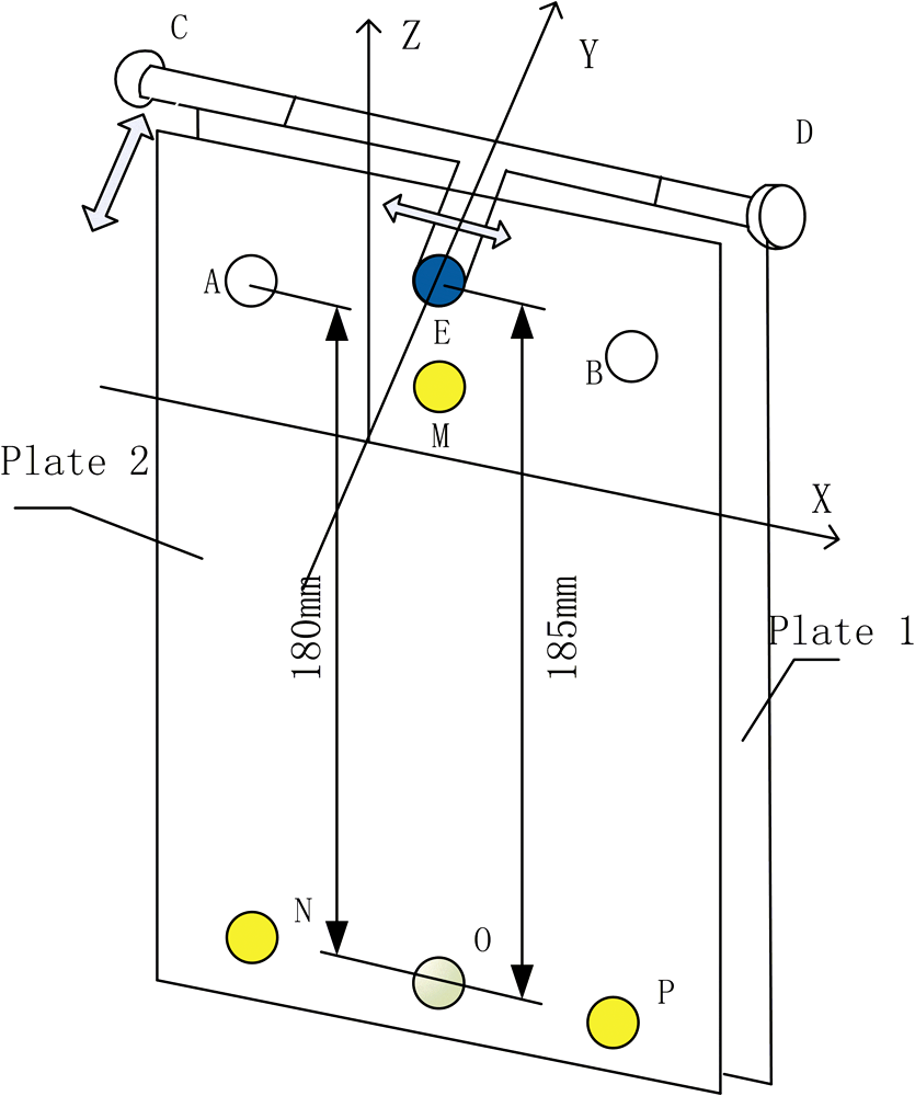
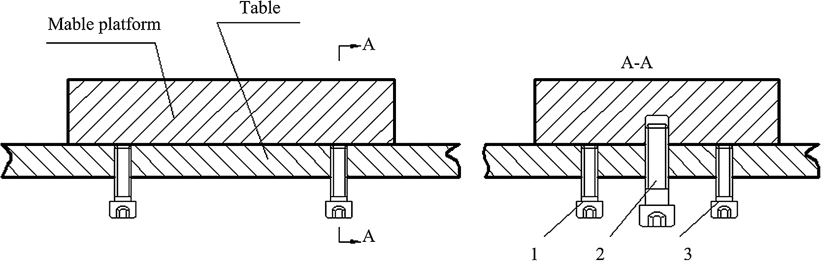
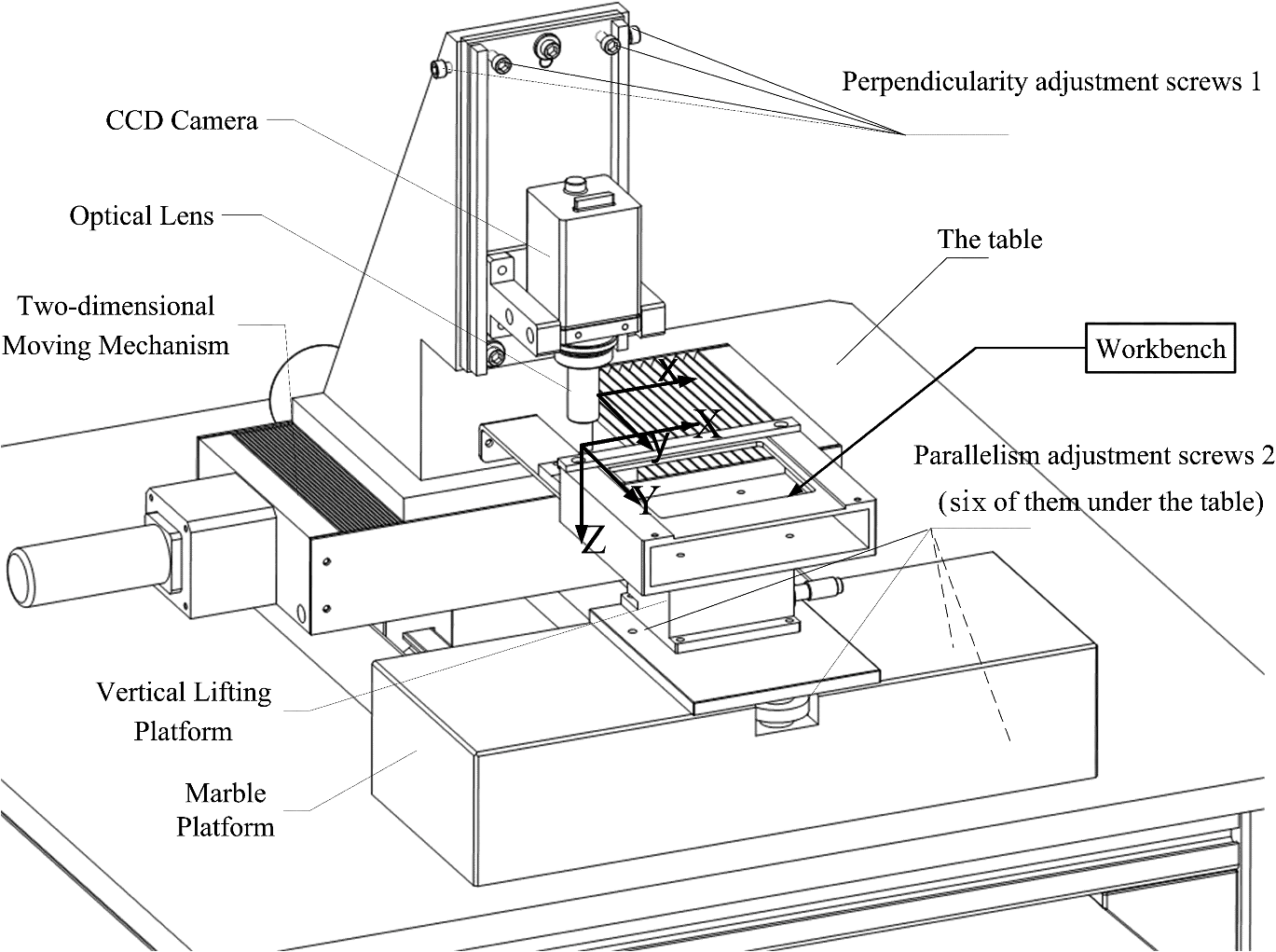
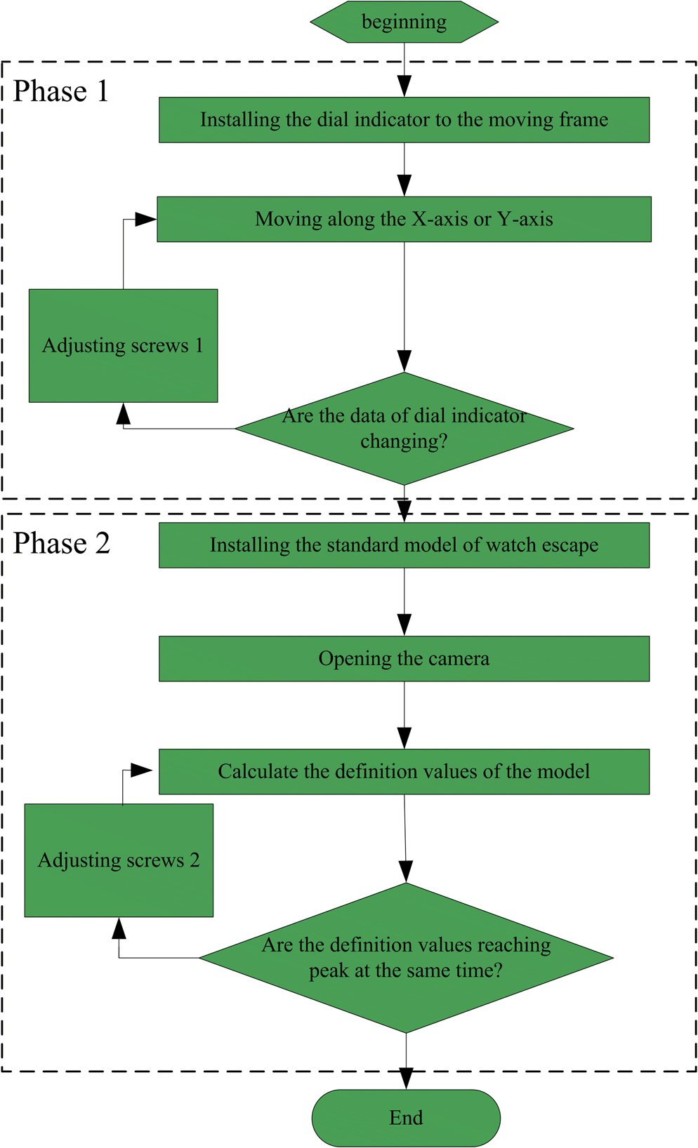
1.IntroductionManufacturers have developed various types of video measuring instruments with high accuracy. However, these instruments are developed based on a “point to point” mode like a microscope to measure different workpieces.1 Due to this low-efficiency work mode, it cannot meet the requirements of detecting a single type of parts in large volumes. Consequently, an instrument termed specialized video measuring system (SVMS) has been taken into consideration. It is designed for a single type of workpiece with a higher accuracy and a higher speed than most conventional video measuring systems (CVMS). For example, one type of SVMS, the video-based inspecting instrument for watch escapement (as shown in Fig. 1) has the following characteristics: (1) A camera with a resolution of pixels captures images of the entire escapement at one shot, and a telecentric lens is designed to keep aberrations as small as possible especially near the edge of the escapement, where most geometric parameters distribute. Integrating the camera and the lens ensures the measuring error is less than 3 μm in an area of 7.4-mm diameter. (2) A novel feed system of placing an array of escapements and a precise motion control system are used to achieve a continuous and automatic measurement of the workpieces.2 The characteristics of the video-based inspecting instrument for watch escapement (VIIWE) can help to reduce the times of photographing and improve detector-positioning speed. Therefore, the SVMS is a feasible solution for the measurements of large-volume parts with a high accuracy. Movement layout is about determining whether the workbench or the shooting component acts as an active one in each axis, since most video measuring systems should be enabled to keep the camera moving relative to workbench multi-directionally. In general, a good movement layout can optimize its structures and functions. The design of a CVMS always follows a traditional rule of mechanical design called “moving the lighter.” It means the lighter one will be assigned as the moving part after comparing the weight of the workbench and the shooting component. For example, the CNC-250 (OGP Corp, Rochester, State of New York) moves the shooting component because it is lighter than the workbench, while the CNC-600 moves the workbench for it weighs less. This rule is useful for a system to measure various objects with more portable structure. However, a lot of problems will occur if we still insist on this rule when a part is measured with particular requirements. A problem is encountered in the design of VIIWE. The workbench is lighter than the shooting component. Nevertheless, if the workbench is moved horizontally, other requirements, such as arranging the workpieces as an array and keeping each of them in the field of view when they are being measured, will not be satisfied. Therefore, we investigate different SVMS layouts, and choose the best one for the VIIWE. In addition, it is well known that image sharpness mainly depends on whether the workpiece is within the depth of field or not. Then, another problem occurs in the design of VIIWE. In order to save the system’s adjusting time, focusing is not recommended when a group of workpieces on the workbench of the VIIWE are measured respectively and automatically. The similar magnification for every sharp image allows very slight changes in the object distance when the camera moves relative to an object. So the proper lens should be telecentric and have only a depth of field of 100 μm by the formulas in Leslie’s view camera technique.3,4 The range is rather narrow; however, several factors result in the distance between lens and the measured object changing, such as the perpendicularity of optical axis to workbench and the parallelism of probe movement plane to workbench. As a result, the allowed range for each factor is narrower. To meet such a requirement, an adjustment method is developed to limit errors in both parallelism and perpendicularity. Some studies have been done for the layout of SVMS. Chen and Li have designed a method of automatic sensor placement for model-based robot vision, which allows three-dimensional (3-D) images to be taken from different vantages of viewpoints.5 Scott has developed a multi-phase, model-based approach to view planning for an automated, high fidelity object inspection or reconstruction by means of laser scanning range sensors.6 Most of the previous studies emphasize on the vision sensor planning while few of them can be referred to the movement parts’ layout. Meanwhile, there are many classic methods on the adjustment technology in SVMS.7–9 For example, Ryoo and Doh estimate the deviated neutral position of the objective lens from the optical axis by the power intensity of a laser spot and then add pulses to the driving input of a fine actuator to align the objective lens to the optical axis. This method has the advantages of convenience, simpleness, and real time, but it only works well in a short measuring distance, and its accuracy is not high enough for the measurement at micron scale. We have to admit not such a perfect adjustment scheme which is available for all types of SVMS. Different adjustment methods need to be adopted according to different requirements. The remainder of the paper is divided into five sections. In Sec. 2, after having reviewed the movement layouts of SVMS, we introduce how to choose a layout for VIIWE. Section 3 details the factors of changing the object distance. The design of the adjustment scheme is described in the Sec. 4. The whole design, the phases of adjustment, and the experimental results are shown in the Sec. 5. Section 6 summarizes our results. 2.Movement Layout for Video-Based Inspecting Instrument for Watch EscapementThe visual detector in a video-based measurement system usually works with two motions: photographing and feeding.10 Photographing, completed by a command from the computer to trigger the camera shutter, is almost irrelevant to the structure of the instrument. However, feeding, which is a relative motion between the camera and the workbench, is completed by corresponding executive components that compose the main structure of the instrument. Therefore, choosing the workbench or the shooting component as a moving part in each direction becomes the main problem in designing the movement layout. As shown in Fig. 2, there will be eight layout solutions in total supposing all feeding movements of the instrument distributed in -, -, and -directions are linear. If the rotational motion or more linear movements are considered, there would be more layout forms which are not required for the VIIWE and therefore will not be discussed further in this paper. The tested object in the VIIWE is the escape wheel of a mechanical watch as shown in Fig. 3. Both the escape wheel and the workbench carrying objects are lighter than the shooting component that is composed of a camera, a lens, and holders. Thus, the layout form as shown in Fig. 2(a) should be chosen if we obey the rule of mechanism design, moving the lighter.10 However, capturing the image of escapement entirely at one shot requires the upper surface of the tested object uncovered. If the scheme in Fig. 2(a) was applied, it would be rather difficult to mount the tested object properly because the gripping mechanism could damage the integrity of an image. Furthermore, placing the tested objects freely would damage the stability of the array type due to the acceleration when the workbench starts or stops. The layouts in Fig. 2(d)–2(f) have the same drawbacks as in Fig. 2(a). Only ones in Fig. 2(g) and 2(h) could meet the requirements of placing the tested object freely and regularly while keep the workbench stationary in the horizontal plane. The layout in Fig. 2(g) is eventually used. It obeys the rule of moving the heavier in the and directions while only keeping the conventional designing concept of moving the lighter in the direction. This type of movement layout also benefits the perpendicularity between the optical axis and the object plane, which will be discussed later. 3.Error AnalysisGenerally, it is necessary to pre-determine whether the image is clear enough for the imaging to progress. The defocus of the system is limited to by using the square gradient image definition evaluation function.3,11 The total error along the optical axis cannot exceed 90 μm due to the restriction of only 100 μm in the depth of field. Actually, both the 3-D movement errors and the original assembly error will result in a change of the object distance.12 The 3-D movement errors can be divided into the error of parallelism between probe movement plane and workbench and the error in the straight, vertical motion. The original assembly error can be regarded as the error of perpendicularity between optical axis and workbench. 3.1.Perpendicularity AnalysisWhen the optical axis is not perpendicular to the workbench, a circle will be imaged as an ellipse because most lenses can only focus on the frontal parallel plane. Therefore, the deviation angle between the optical axis of the shooting component and the workbench must be small enough to obtain an undistorted image.13 As shown in Fig. 4, the line represents that the theoretical object plane perpendicular to the optical axis, while the line represents the tilted situation with the radial error caused by the deviation angle . The lengths of both and are equal to 7.4 mm. To capture an undistorted image, must be less than 3 μm, the accuracy for the watch escapement; and the allowed deviation angle will be less than 1.63 deg by Eq. (1). Such a precision is not too high to be realized in a measuring instrument. However, a higher demand on perpendicularity is required by further analysis of defocus effects caused by the vertical deviation angle.14,15 When approaches 1.63 deg, will be about 210.5 μm by Eq. (2). It is far beyond the allowed depth of field and will cause the image to be blurred. In fact, has to be limited to to meet the requirement of depth of field. And meanwhile, needs to be less than 0.155 deg, which is somewhat difficult to realize. Note that there is a perpendicularity change as long as the vertical trajectory is not just along the -axis, no matter if the workbench or the shooting device is used to accomplish -axis movement. In the VIIWE, there are only two cases for feeding vertically involving a calibration of perpendicularity (see Sec. 5), switching to workpieces with different thickness; and the ranges of both cases are below 0.3 mm. For this reason, we choose a precise lift bench, Seiki B33-80 (Suruga, Shizuoka, Japan) with a dimension of , as a power source in the vertical movement. The parallelism error of the upper surface relative to the original plane is less than 5 μm, and the straightness error in vertical motion is less than 3 μm. Figure 5(a) and 5(b) shows the shooting device and the workbench as a -axis movement unit separately. Here, , and represent the length of -axis feeding, the straightness of the lift, and the maximum value of the surface’s parallelism, respectively. According to the theory of triangle, the vertical deviation angle in Fig. 5(a) can reach 0.573 deg, which is beyond the limit of vertical deviation angle. The deviation angle in Fig. 5(b) is only 0.003 deg, which has less influence on measurement results. Therefore, with workbench acting as the movement layout along the -axis, the movement layout form in Fig. 2(g) will be better than the one in Fig. 2(h) for its benefit of the perpendicularity. 3.2.Parallelism AnalysisIndeed, the deviation of perpendicularity affects the error of object distance partially, while the deviation of parallelism between probe movement plane and workbench will affect the object distance in the entire workbench.16 As shown in Fig. 6, - and - represent the coordinate systems of the moving camera and the still workbench respectively. If the plane is not parallel to the plane , the object distance error will be introduced. To meet the requirements of depth of field, we have to keep the prerequisites below. The linear parallelism error between the line and the line is kept less than 20 μm per 100 mm. The plane parallelism error between the plane and the plane is less than 50 μm in the entire measuring range. 4.Adjustment for Perpendicularity and ParallelismIt is hard to keep both parallelism and perpendicularity stable because of the strict requirements for the two parameters and the continuous movement of the shooting component when the parts are being measured. Thus, proper methods should be provided to quantify and correct the errors. Unlike many manufacturers who use other high-accuracy devices to calibrate and adjust these two parameters, we design a specialized adjustment scheme for VIIWE for the convenience of users. 4.1.Perpendicularity AdjustmentThe adjustment mechanism about perpendicularity is the carrier of the shooting component. As shown in Fig. 7, the coordinate system is composed of the optical axis and two movement axes and . Both lens and camera are fixed on the plate 1 that is held by plate 2. The rational perpendicularity of the optical axis to workbench can be obtained by adjusting the plate 2 in the plane and plane. The adjustments in both planes rely on the rotational motion, and the two axes of rotations intersect at the point where a pivot pin in a hole is adopted to play the role of the axes in practice. In the plane, the plate 2 is forced to rotate left or right by two long screws marked and in Fig. 7, which are installed in both sides of plate 1, while in plane, the plate 2 rotates backward or forward by the frontal screws marked and in Fig. 7 extruding two flexible gaskets. After adjusting, three inner-hexangular bolts marked as , , and in Fig. 7 fasten plate 1 tightly and keep the perpendicularity stable in case the adjusted screws become loose. In the design of structure, the rotation radius is 180 mm in the plane and 185 mm in the plane. Thin-tooth M5 screws are chosen as the adjusting knobs with a thread pitch of 0.5 mm. Therefore, the adjustment precision can be calculated when turning the screw for one cycle. In the plane: In the plane: In order to quantify the amount of adjustment for these four screws, the perpendicularity is calculated with a regional definition, developed and achieved by a PC with its basic principles summarized as follows. If a deviation angle between the axis of the shooting component and a measured standard model exists, the definition that can be measured by the gray scale contrast with image processing technologies will be different in four different regions of the model. Therefore, the perpendicularity of the machine can be self-calibrated with only one standard model. The amount of screw adjustment can be calculated by Eq. (5). 4.2.Parallelism AdjustmentIn this equipment, we divide a “plane to plane” parallelism adjustment into two orthogonal “line to plane” parallelism adjustments each with the same basic principles. Not only can the screws shown in Fig. 8 fix the marble platform to the table, but they can also adjust the “line to plane” parallelism. Screw 2 is ordinary, and screw 3 has the same tooth as those used in perpendicularity adjustment. In the initial state, the preload of screw 2 is small. The marble platform can be rotated clockwise and anticlockwise by turning screw 1 or screw 3. Tightening screw 2 can increase preload to keep the platform stable. In the testing process, a dial indicator that is mounted on the moving shooting component touches the upper surface of the workbench to calibrate parallelism. It should not stop adjusting the screws until all values the dial indicator shows are very close to each other. The disadvantage of this method is that the amounts of adjustment for the screws could not be calculated quantitatively by Eq. (6) because its accuracy also relates to the unknown preload of the screw 2. However, the following equation will be useful when the parallelism is adjusted iteratively. 5.ResultsFigure 9 shows the concrete structure of the VIIWE. In the layout, a two-dimensional movement mechanism and a lifting bench are used to drive the shooting device to move in three- dimensional space. For the adjustment, the screws 1 and the screws 2 are responsible for the parallelism and the perpendicularity respectively. There are two main phases in the adjustment flow chart as shown in Fig. 10. Phase 1 is to compute deviation angles of parallelism and adjust them, and phrase 2 is responsible for the perpendicularity. Both the perpendicularity and parallelism adjustments are not very complicated. As the deviation angles of parallelism and perpendicularity are both adjusted by the same jiggle screw structure, we only verify the effect of perpendicularity adjustment scheme here. There are four symmetrical regions at two coordinate axes of a standard model with the size of . Adimec4000C (EA, Eindhoven, The Netherlands), a high resolution digital camera, is utilized to capture the image of the four regions simultaneously. The regional definitions are calculated by the gradient square function17 as shown in Table 1. The distance between each two adjacent positions is 10 μm. Region A in position 8, region B in position 11, region C in position 2, and region D in position 5 reach their maximum. In other words, the vertical deviations are in the plane and in the plane. Meanwhile, the deviation angles both in the plane and in the plane reach 0.465 deg by Eq. (2). The two frontal ones of the screws 4 are rotated clockwise for three circles and the two side ones anticlockwise for 2.9 cycles by the following the equation: Table 1Experimental data before adjustment.
The values of regional definitions retested after adjustment are shown in Table 2. The values in four regions reach the maximum at the same position, i.e., the workbench and the optical axis are vertical to each other. The results prove that this procedure is linear, precise, and effective to adjust the perpendicularity of VIIWE. Table 2Experimental data after adjustment.
6.ConclusionThis paper presented a scheme of movement layout and adjustment in design of SVMS with an example of the VIIWE. Two requirements in the VIIWE were placing the watch escapements freely and regularly, capturing a single image entirely with a small depth of field lens. First, the forms of movement layout of the SVMS were discussed, and an optimized one for the VIIWE was chosen. Second, an adjustment scheme was introduced after analyzing the influences on image sharpness caused by parallelism and perpendicularity. The movement layout we chosen not only met the requirements of placing the watch escapements, but also benefited the perpendicularity of the VIIWE. The precision of the adjustment mechanism could be better than 10’, which enabled us to keep the workpieces within a small depth of field all the way. Our method is intuitive and useful for other SVMS designs. AcknowledgmentsThis project is funded by Major Science and Technology Funded Project of National High-grad CNC (2009ZX04014-092) and Research on the Automatic Flexible Measurement and Automatic Separation Technology (NO. 09JCZDJC26700). ReferencesF. Mason,
“Video measurement,”
Qual. Manuf., 24
(11), 11
–12
(2001). Google Scholar
Z. WangZ. W. Wang,
“Semi-automatic inspecting instrument for watch escape wheel based on machine vision,”
in Seventh International Symposium on Precision Engineering Measurements and Instrumentation,
(2011). Google Scholar
S. Leslie, View Camera Technique, 136
–139 3rd ed.Focal Press, London
(1976). Google Scholar
J. Zhanget al.,
“Verticality detection algorithm based on local image sharpness criterion,”
Chin. J. Mech. Eng., 25
(1), 173
–178
(2012). CHHKA2 0577-6686 Google Scholar
S. Y. ChenY. F. Li,
“Automatic sensor placement for model-based robot vision,”
IEEE Trans. Syst. Man Cybern. B, 34
(1), 393
–408
(2004). http://dx.doi.org/10.1109/TSMCB.2003.817031 ITSCFI 1083-4419 Google Scholar
W. R. Scott,
“Model-based view planning,”
Mach. Vis. Appl., 20
(1), 47
–69
(2009). http://dx.doi.org/10.1007/s00138-007-0110-2 MVAPEO 0932-8092 Google Scholar
J. R. RyooT. Y. Doh,
“Auto-adjustment of the objective lens neutral position in optical disc drives,”
IEEE Trans. Consum. Electr., 53
(4), 1463
–1468
(2007). http://dx.doi.org/10.1109/TCE.2007.4429238 ITCEDA 0098-3063 Google Scholar
K. Yokoyamaet al.,
“Optical beam deflection noncontact atomic force microscope optimized with three-dimensional beam adjustment mechanism,”
Rev. Sci. Instrum., 71
(1), 128
–132
(2000). http://dx.doi.org/10.1063/1.1150174 RSINAK 0034-6748 Google Scholar
Optics Design and Optics Measurement, 537
–544 Optical instrument design manual editing group, Mechanical Industry Press, China
(1971). Google Scholar
A. L. Wanget al., Modern CN Machine, 281
–296 National Defense Industry Press, China
(2005). Google Scholar
J. Zhanget al.,
“Super-resolution reconstruction of image in high accuracy image measuring system,”
Opt. Precis. Eng., 19
(1), 168
–174
(2011). Google Scholar
E. Goronet al.,
“Original 3D feeding structures for enhancing microstrip antennas operating bandwidth,”
in 35th Microwave Conference,
(2005). Google Scholar
H. Gonget al.,
“A method of verticality adjusting between optical axis and carrier in two-dimensional vision measurement,”
J. Beijing Inform. Sci. Technol. Univ., 21
(3), 35
–38
(2006). Google Scholar
T. Y. YuH. Y. Tan, Engineering Optics, 58
–63 Mechanical Industry Press, Beijing
(2002). Google Scholar
W. J. Smith,
“Aberrations,”
Modern Optical Engineering, 71
–72 SPIE Press McGraw-Hill, Bellingham, Washington, USA
(2000). Google Scholar
G. SansoniP. BellandiF. Docchio,
“Design and development of a 3D system for the measurement of tube eccentricity,”
Meas. Sci. Technol., 22
(7), 1
–12
(2011). http://dx.doi.org/10.1088/0957-0233/22/7/075302 MSTCEP 0957-0233 Google Scholar
J. J. ZhaoR. L. BaiD. Li,
“A new method of verticality adjusting between optical axis and object surface of embedded machine vision controller,”
Optoelectr. Eng., 37
(5), 63
–69
(2010). Google Scholar
Biography Xinbo Liu received his master’s degree from Tianjin University in 2007. Now he is studying in the College of Precision Instrument and Opto-electronics Engineering of Tianjin University as a PhD candidate. His main research interests are precision measurement and machine-tool calibration.  Zhong Wang gained his master’s degree from Tianjin University in 1991. Now he is a professor of Tianjin University in China. His main research interests are precision measurement, instrument intelligence, micro-accessory measurement technology based on full imaging and on-time detection, and classification technology in industry. |
|||||||||||||||||||||||||||||||||||||||||||||||||||||||||||||||||||||||||||||||||||||||||||||||||||||||