|
|
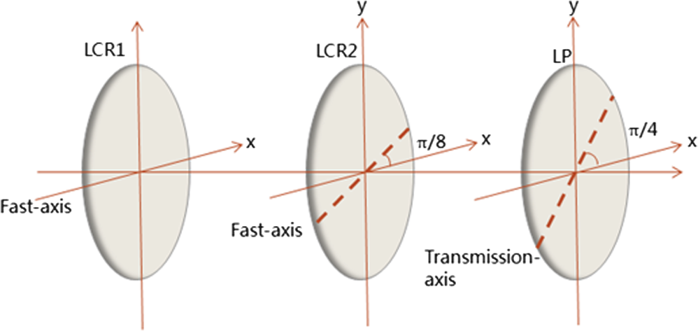
1.IntroductionLaser radar, also referred to as ladar or lidar, uses eye-safe lasers to measure the range and other properties of targets. ladar shares many of the basic features of common microwave radar. But due to its extremely short operating wavelength and small beam size, it has been utilized extensively for defensive purposes such as in-port threat defense and shipboard protection systems since its invention.1–3 The capabilities of a ladar imaging system can be further enhanced if the light reflected from objects can be analyzed polarimetrically.4–7 The term polarization, used to describe the complex direction of an electric field vector, plays an essential role in the interaction of light and matter.8 Polarimetric imaging techniques take advantage of the fact that a given object emits and scatters light in a unique way depending on its properties, which allows us to distinguish objects with similar reflectivity but different polarimetric features. By breaking down the light into independent polarization components, one can often reveal occluded surface information such as composition, texture, and roughness. As such, polarimetric imaging is widely used in many situations. For example, astrophysicists use polarimeters to measure the spatial distribution of magnetic fields on the surface of the sun.9 In the field of medical imaging, researchers analyze the polarization of light through coherence interferometry to yield details about the optical properties of biological tissues.10–12 For defense applications, polarization imaging is often used to detect objects through smoke and obscurants such as vegetation or camouflage.13 An arbitrary polarization state of light can be represented by a column vector called the Stokes vector, denoted as . Each element in this vector is a linear combination of two orthogonal polarization components, which is illustrated explicitly in Sec. 2. Over the years, many designs have been used to measure the Stokes vector of light, such as a three-camera architecture designed by Prosch,14 a liquid crystal polarization camera by Andreou and Wolff,15 and a dual piezoelastic modulator system by Stenflo and Povel.16 In this paper, we report a fully automated polarization-sensitive ladar (pladar) system that operates at a speed much higher than the classical Stokesmeter. This work builds on previous polarimetric studies carried out by our group.12,17,18 Our system is capable of detecting all four components of the Stokes vector of light reflected from the object at video-rate. In addition, by varying the input polarization state, full Mueller matrix imaging is also realizable with such a system. An example of such full Muellermetric imaging employing variable input polarization was recently demonstrated by us12 in a somewhat different setting. 2.Stokes–Mueller FormalismPolarization-dependent reflectivity is quite common in nature. In fact, every surface alters the polarization of the incident radiation, if very slightly. Any arbitrary polarization state of the light can be represented by the well-known Stokes vector, which is defined in terms of two orthogonal components of the oscillating electric field (denoted as and in this paper) perpendicular to the direction of propagation. where the brackets imply averaging over the observation time . is the overall intensity, denotes the intensity difference between vertical and horizontal linear polarizations, stands for the intensity difference between linear polarizations at and , and is the intensity difference between left and right circular polarizations. for completely polarized light, and for partially polarized/unpolarized light.In the Mueller—Stokes formalism, a matrix, called the Mueller matrix (denoted as ), is often used to describe mathematically the transformation of the polarization of light by a medium.19 The Mueller matrix relates the Stokes vectors of incoming and outgoing light (denoted as and , respectively) via the relation . The net Mueller matrix of any optical system is given by the ordered product of the Mueller matrices of the individual elements. From the elements of the Mueller matrix, we can infer the properties of the medium, such as the reflectance, absorption, and birefringence. The Stokes–Mueller formalism is more comprehensive than the Jones vector approach, even though they both rely on linear algebra and matrix formalisms. Specifically, the Stokes vector encompasses any polarization state of light, whether it is completely orpartially polarized, while the Jones vector deals only with fully polarized light. 3.Automated Inline StokesmeterA typical Stokesmetric imaging system consists of a polarization state generator (PSG) and a polarization state analyzer (PSA). The PSG controls the input polarization state of the light. The PSA analyzes the polarization of the light reflected by the object. The conventional PSA consists of a quarter wave plate (QWP) and a linear polarizer (LP), and requires the QWP to be inserted and removed between various readings.20 Consequently, the speed of the system is greatly limited, which hinders it from being integrated into a real-time ladar system. We proposed and demonstrated a PSG consisting of a pair of liquid crystal retarders (LCRs) and a polarizer in series to circumvent this problem in our previous study.17 Due to the anisotropic optical property, an LCR can produce arbitrary retardation based on the voltage applied on it. This flexibility allows a configuration of the PSA free of insertion/removal, as shown in Fig. 1. This architecture, which has been investigated theoretically as well as experimentally,21–24 forms the foundation of our pladar system. Like the classical Stokesmeter, four measurements are required to determine the Stokes vector of the unknown light. Table 1 lists the required phase delays of the LCRs for each measurement for such an architecture. The Stokes vector can be calculated on the basis of the four distinctly measured intensities with the following equation: Table 1Phase delay of the LCRs for each measurement of the inline Stokesmeter.
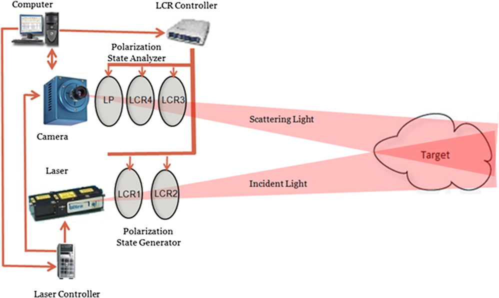
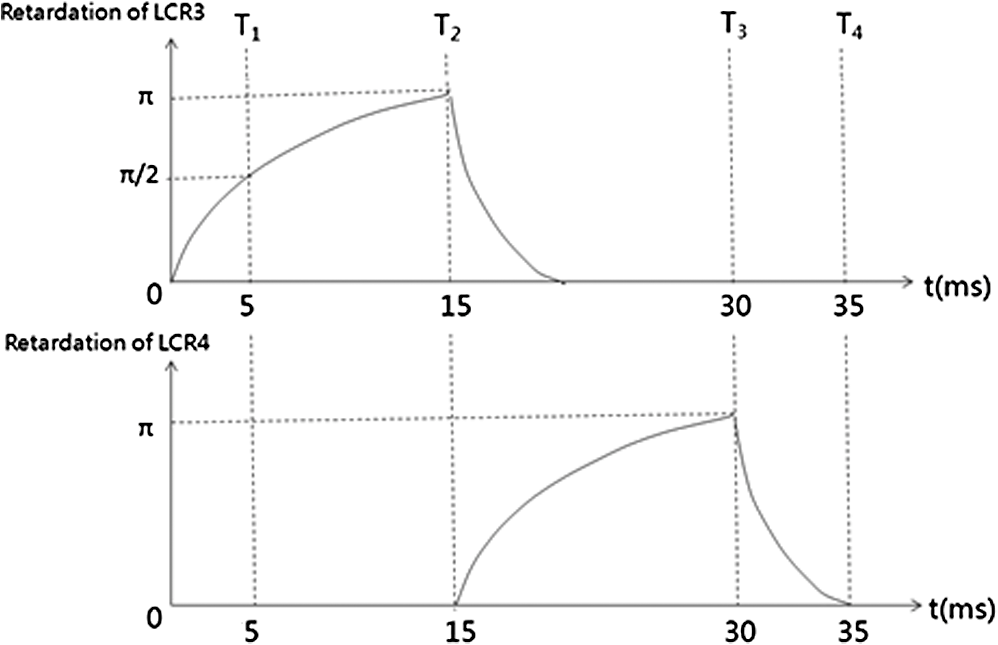
4.Fully Automated Polarimetric Ladar SystemThe basic configuration for the pladar is illustrated schematically in Fig. 2. A pulsed laser at 1571 nm () is used as the light source. The Stokes imaging occurs in the following order: At the pre-detection stage, the computer sends signals to the LCR controller as well as the laser controller. The LCR controller sets the LCRs in proper states. Once the LCRs are ready, the laser controller triggers the pulse and the camera simultaneously. The source laser is first sent through the PSG to produce the desired polarization before hitting the target. The backscattered light transmits the PSA and is then detected by the infrared camera, which has a CCD array of pixels with pixel size. An exposure time window is applied to the camera to eliminate unwanted background noise. The recorded intensity data array is transmitted back to the computer, where the Stokes vector of each pixel is calculated simultaneously by a computer program, thus producing four distinct images, corresponding to the four Stokes parameters, for the input scene. The operation speed of this pladar system is determined primarily by the response time of the LCRs. As mentioned in Sec. 3, to analyze the Stokes vector, four independent measurements with different LCR phase delays are required. For the LCRs used in our experimental setup, it takes 15 ms for the retardation to increase from 0 to , and 5 ms to relax from to 0. The activation and relaxation of phase delay of each LCR in a measurement cycle is shown in Fig. 3. Compared with the response time of the LCRs, the exposure window for light detection (1 μs for the camera in our setup) is negligible. The intensities , , , and listed in Table 1 are recorded at times , , and , respectively. For our current setup, completing one cycle of four measurements for any input scene takes about 35 ms, enabling the ladar system to operate at video-rate. 5.Stokesmetric Imaging of Various ScenesWe first tested the pladar imaging system with an artificial scene composed of optical elements with well-defined polarimetric properties. Specifically, we mounted a polarizer (at 45 deg) and a QWP on a piece of metal. Right circularly polarized light is generated using the PSG to illuminate this artificial scene. The resultant four Stokes vector images of the reflected light are shown in Fig. 4. The false red/blue color is imposed by the software to represent positive/negative value, respectively. Figure 4(a), corresponding to the element in the Stokes vector, contains only intensity-based information. Figure 4(b) through 4(d) are the , , and images of the Stokes vector. Since our target objects are almost transparent, they can barely be distinguished from the background. However, because the tilted polarizer only selects 45 deg polarization to pass while the rest of the scene does not, it is easily distinct in Fig. 4(c) containing only the element. Similarly, because the QWP produces an extra phase shift to the incident light in a round trip, the image of it appears red, while the surroundings appear blue. Such an obvious contrast makes it possible to detect easily the almost transparent QWP in Fig. 4(a). After validating the capabilities of the automated pladar system, we used it to capture the Stokesmetric images of targets merged in more complicated scenes. Figure 5 shows a sample image set obtained for one such scene. We imitated the scene of a harbor by placing model boats on still water. A crystal is placed between two windows of the boat, and transparent tape is attached to the body of the boat to form the phrase “work boat.” As can be seen, both the crystal and the letters can hardly be recognized from Fig. 5(a); however, Fig. 5(c), corresponding to the vector (containing purely 45 deg polarized light), clearly depicts the crystal due to its birefringence. The word “work boat” is also readable in Fig. 5(c) from the body of the boat because of its different polarimetric signature from the surroundings. This ability to identify and distinguish various surfaces with a very high contrast makes pladar a promising tool for surveillance and tracking applications. Note that for this imaging system, the angle of view (AOV) is primarily determined by the dimension of the CCD sensor and the effective focal length (EFL) of the camera. In our current setup, the CCD sensor area and the 16 mm EFL of the relay lenses yield an AOV of 31.5 deg and 27.0 deg in the horizontal and vertical directions, respectively. The AOV can be enhanced further by increasing the size of the CCD for applications such as wide-area surveillance. Fig. 5Stokesmetric images produced under right circularly polarized light, for an artificial harbor. 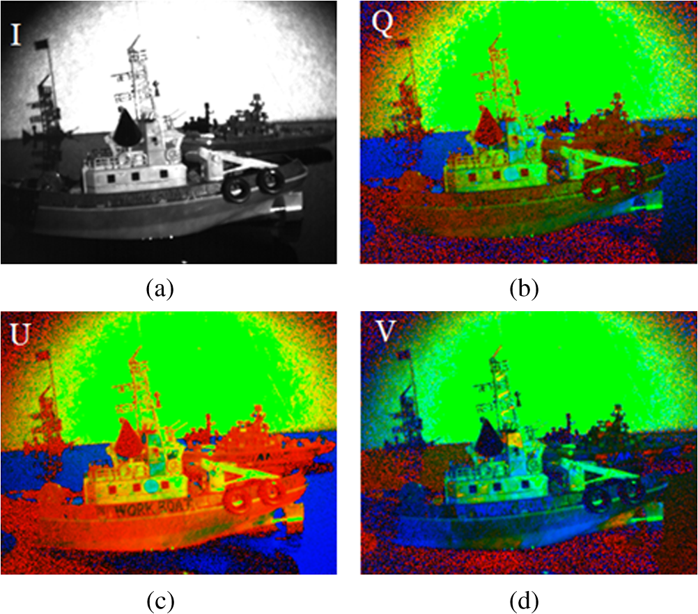 By measuring the Stokes parameter images for a set of different input polarizations states, it would be possible to produce the full set of Muellermetric images, in a manner similar to what we have demonstrated recently for a polarimetric optical coherence tomography system.12 This work is in progress and will be reported in a future publication. 6.SummaryThe polarimetric information embedded in the images of a scene is not detected by an intensity-image-based ladar system. In this paper, we report the implementation of a fully automated, video-rate polarimetric ladar system that is capable of detecting the Stokes vector of the reflected light. The polarimetric images of the artificial scenes reveal information not detectable by intensity-based ladar. It is also possible to perform full Muellermetric imaging with such a system by controlling the input polarization state of light. AcknowledgmentsThis work is supported in part by AFOSR grants FA9550-06-1-0466 and FA9550-10-1-0228, NASA grant NNX09AU90A, and NSF Crest grant 0630388. One of the authors, Renu Tripathi, acknowledges support from National Science Foundation NSF-CREST (grant 0630388), and NASA URC-5 (grant NNX09AU90A). ReferencesL. J. Sullivan,
“Infrared coherent radar,”
Development of Coherent Laser Radar at Lincoln Laboratory, 227 148
–161 SPIE Press, Lexington, MA
(1980). Google Scholar
W. G. Egan, Optical Remote Sensing Science and Technology, Marcel Dekker(2004). Google Scholar
B. W. Henderson,
“‘Firefly’ laser experiment successful in measuring inflatable decoy motion,”
Aviat. Week Space Technol., 132
(17), 75
–76
(1990). AWSTAV 0005-2175 Google Scholar
T. NeeS. F. Nee,
“Infrared polarization signatures for targets,”
Proc. SPIE, 2469 231
–241
(1995). http://dx.doi.org/10.1117/12.210594 PSISDG 0277-786X Google Scholar
P. J. Curran,
“Polarized visible light as an aid to vegetation classification,”
Remote Sens. Environ., 12
(6), 491
–499
(1982). http://dx.doi.org/10.1016/0034-4257(82)90023-2 RSEEA7 0034-4257 Google Scholar
M. J. Duggin,
“Imaging polarimetry in scene element discrimination,”
Proc. SPIE, 3754 108
–117
(1999). http://dx.doi.org/10.1117/12.366321 PSISDG 0277-786X Google Scholar
S.-Y. LuR. A. Chipman,
“Interpretation of Mueller matrices based on polar decomposition,”
J. Opt. Soc. Am. A, 13
(5), 1106
–1113
(1996). http://dx.doi.org/10.1364/JOSAA.13.001106 JOAOD6 0740-3232 Google Scholar
B. J. DeBooJ. M. SasianR. A. Chipman,
“Depolarization of diffusely reflecting man-made objects,”
Appl. Opt., 44
(26), 5434
–5445
(2005). http://dx.doi.org/10.1364/AO.44.005434 APOPAI 0003-6935 Google Scholar
H. LinT. Rimmele,
“The granular magnetic fields of the quiet sun,”
Astr. Phys. J., 514
(1), 448
–455
(1999). http://dx.doi.org/10.1086/306925 Google Scholar
J. F. de BoerT. E. MilnerJ. S. Nelson,
“Determination of the depth-resolved Stokes parameters of light backscattered from turbid media by use of polarization-sensitive optical coherence tomography,”
Opt. Lett., 24
(5), 300
–302
(1999). http://dx.doi.org/10.1364/OL.24.000300 OPLEDP 0146-9592 Google Scholar
E. Götzingeret al.,
“Measurement and imaging of birefringent properties of the human cornea with phase-resolved, polarization-sensitive optical coherence tomography,”
J. Biomed. Opt., 9
(1), 94
–102
(2004). http://dx.doi.org/10.1117/1.1629308 JBOPFO 1083-3668 Google Scholar
X. Liuet al.,
“White light interferometric detection of unpolarized light for complete Stokesmetric optical coherence tomography,”
Opt. Commun., 284
(14), 3497
–3503
(2011). http://dx.doi.org/10.1016/j.optcom.2011.03.054 OPCOB8 0030-4018 Google Scholar
M. J. DugginG. J. KinnM. Schrader,
“Enhancement of vegetation mapping using Stokes parameter images,”
Proc. SPIE, 3121 307
–313
(1997). http://dx.doi.org/10.1117/12.283864 PSISDG 0277-786X Google Scholar
T. ProschD. HenningsE. Raschke,
“Video polarimetry: a new imaging technique in atmospheric science,”
Appl. Opt., 22
(9), 1360
–1363
(1983). http://dx.doi.org/10.1364/AO.22.001360 APOPAI 0003-6935 Google Scholar
L. WolffA. Andreou,
“Polarization camera sensors,”
Image Vis. Comput., 13
(6), 497
–510
(1995). http://dx.doi.org/10.1016/0262-8856(95)94383-B IVCODK 0262-8856 Google Scholar
H. PovelH. AebersoldJ. O. Stenflo,
“Charge-coupled device image sensor as a demodulator in a 2-D polarimeter with a piezoelastic modulator,”
Appl. Opt., 29
(8), 1186
–1190
(1990). http://dx.doi.org/10.1364/AO.29.001186 APOPAI 0003-6935 Google Scholar
X. Liuet al.,
“High-speed inline holographic Stokesmeter imaging,”
Appl. Opt., 48
(19), 3803
–3808
(2009). http://dx.doi.org/10.1364/AO.48.003803 APOPAI 0003-6935 Google Scholar
J.-K. LeeX. LiuM. S. Shahriar,
“Volume-grating Stokesmeter based on photonic bandgap structures,”
Appl. Opt., 48
(17), 3212
–3215
(2009). http://dx.doi.org/10.1364/AO.48.003212 APOPAI 0003-6935 Google Scholar
D. Goldstein, Polarized Light, 3rd ed.CRC Press, New York, NY
(2010). Google Scholar
C. Brosseau, Fundamentals of Polarized Light: A Statistical Optics Approach, Wiley, New York
(1988). Google Scholar
J. M. Bueno,
“Polarimetry using liquid-crystal variable retarders: theory and calibration,”
J. Opt. A., 2
(3), 216
–222
(2000). http://dx.doi.org/10.1088/1464-4258/2/3/308 JOAOF8 1464-4258 Google Scholar
A. De Martinoet al.,
“Optimized Mueller polarimeter with liquid crystals,”
Opt. Lett., 28
(8), 616
–618
(2003). http://dx.doi.org/10.1364/OL.28.000616 OPLEDP 0146-9592 Google Scholar
B. Laude-Boulesteixet al.,
“Mueller polarimetric imaging system with liquid crystals,”
Appl. Opt., 43
(14), 2824
–2832
(2004). http://dx.doi.org/10.1364/AO.43.002824 APOPAI 0003-6935 Google Scholar
F. Goudailet al.,
“Target detection with a liquidcrystal-based passive Stokes polarimeter,”
Appl. Opt., 43
(2), 274
–282
(2004). http://dx.doi.org/10.1364/AO.43.000274 APOPAI 0003-6935 Google Scholar
|