|
|
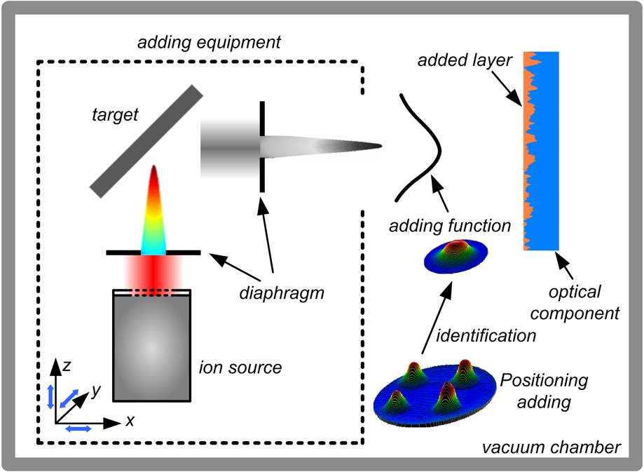
1.IntroductionCurrently, with the improvement of the performance of modern optical systems, worldwide efforts are being made to meet the increasing requirements for high-precision figure and surface quality. In the optics field, probably the most stringent conditions for surface accuracy and smoothness are made on optical components for deep ultraviolet and extreme ultraviolet lithography, where the specifications for the surface error and roughness need to achieve sub-nanometer precision simultaneously 1,2 After considerable research, Carl Zeiss in Germany points out that ion beam figuring (IBF) is the most suitable method for the final figuring of lithography optics2, which sufficiently embodies the machining capability of IBF. However, the correcting capability of IBF for surface errors is directly determined by the dimension of the removal function.3 To improve the correcting capability, lots of recent research has been conducted to control the ion beam size within sub-millimeter.1,4,5 Obviously the ion beam size cannot be reduced without limit, which makes IBF usually only specialize in correcting the low spatial frequency errors. Moreover, the evolution mechanism of surface roughness is not completely clear under ion bombarding. In the actual figuring process, some references even indicated that the surface quality cannot be improved and potentially becomes even rougher.6,7 Therefore, current IBF technology has no obvious effect on correcting the mid-to-high spatial frequency errors, which is a key problem existing in the development of IBF technology. In this paper, we propose a new method for figuring high-precision optical surfaces by combining ion beam material adding (IBA) and IBF. This combined method can realize the uniform convergence of surface errors, where the IBA is first utilized to improve surface accuracy and quality while IBF is used to further improve the surface accuracy. 2.Ion Beam Adding MechanismShown in Fig. 1, the IBA process utilizes a Kaufman ion beam source with an ion diaphragm to bombard the target material, and a stable particle beam is generated to deterministically add material to the local pits on optical surface. Based on the computer-controlled optical surfacing (CCOS) principle, the IBA method described here assumes a constant particles adding, so that the process can be represented by a convolution equation and the dwell time solution is a deconvolution operation. In the IBA process, the local pits on the optical surface is corrected through rastering the stable particles beam across the workpiece at varying velocities according to the dwell time. In the IBA process, a fixed ion beam bombarding the target material can maintain a constant adding rate, where the adding rate deviation of the adding function can be controlled within for one hour. The ion beam system can produce a near rotationally symmetric Gaussian adding function, which also has high correcting capability, as well as IBF. In addition, the adding function dimension and adding rate can be adjusted to adapt various optical components with different pit defects. All of these make IBA a high-precision and high-deterministic figuring method. 3.Experiments and DiscussionBefore processing, an adding function was determined through a positioning-adding experiment and identified by interferometry (shown in Fig. 1). Experiments are performed on our self-developed ion beam system at fixed ion energy , 30 mA beam flux with ions, and the sputtering target material is . As shown in Fig. 1, the adding function is also a near rotationally symmetric Gaussian shape with peak adding rate /min and dimension . For investigations of the surface accuracy and surface quality, the Zygo-GPI XP interferometer and Zygo-New View 700 are applied, respectively. A fused silica sample (aperture 90 mm) is first processed by IBA with the above-mentioned adding function. Figure 2(a) shows the original surface accuracy before processing 110.2 nm peak-to-valley (PV) and 23.0 nm root mean square (RMS). It takes one iteration and about 27.5 min to figure this sample and the surface error is reduced down to 49.9 nm PV and 6.5 nm RMS [shown in Fig. 2(b)]. In the IBF process, the removal function with dimension and peak removal rate /min is used to further improve the surface accuracy. The final surface accuracy reaches 10.4 nm PV and 1.3 nm RMS [shown in Fig. 2(c)] after three iterations within 35.5 min. The total time consumed in the combined figuring experiment is only 63 min, but the total convergence ratio reaches 17.7. Moreover, the power spectral density (PSD) curve in Fig. 2(d) indicates that the surface errors within measured range are uniformly converged after combined figuring method. Figure 3 shows that the improvement for surface roughness is obvious in IBA, whose Ra (Average Roughness) value is reduced sharply from original 0.78 nm down to 0.44 nm and the PSD curve also decreases uniformly at different spatial frequencies. Simultaneously, the surface roughness was kept invariable in IBF process. This experimental result validates the correcting capability of the IBA method for mid-to-high spatial frequency errors. Therefore we demonstrated that the combined figuring technology extend the machining capability of current IBF technology. Fig. 2Experimental results of combined figuring: (a) original surface error, (b) surface error after IBA, (c) surface error after IBF and (d) PSD curve for surface error in combined figuring process. 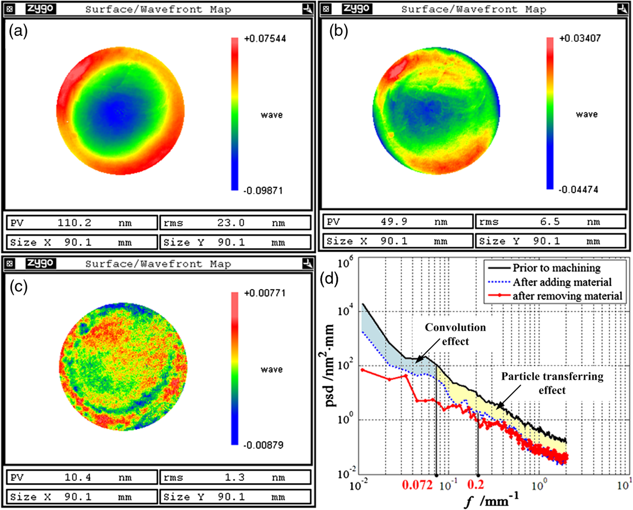 Fig. 3Surface roughness evolution of figuring process: (a) original surface roughness, (b) surface roughness after IBA, (c) surface roughness after IBF and (d) PSD curve for surface roughness in combined figuring process.  According to the CCOS principle, where the material removal is a convolution of the removal function and the dwell time , which can be expressed as Because the actual removal function always possesses a beam dimension, the actual material removal is always more than the anticipant material removal . Based on this model, we have defined a figure of merit, named material removal availability , to evaluate the correcting capability of the removal function,3,8 given as follows: where is the spatial wavelength of the error.The correcting capability is very low when the material removal availability is down to 0.1 (Ref. 8), where the corresponding frequency is the correcting cutoff frequency The PSD curves shown in Figs. 2(d) and 3(d) show that the correcting cutoff frequency in IBF is about and can keep the surface roughness invariable. Combining the removal function dimension with Eq. (3), we can know the experimental results are identical with the theoretical analysis. Based on above analysis, theoretically the correcting cutoff frequency of the adding function with is about . However, the experimental results presented in Figs. 2(d) and 3(d) are different from the theoretical analysis, where the surface errors with periodic dimensions from the full aperture down to the micrometer scale roughness are uniformly converged. So it has to be noted that there is a strong particles-transferring effect for correcting surface errors in IBA except for the convolution effect of the CCOS principle. Shown in Fig. 4, when the high energy particles reach the optical surface, they still have enough energy to transfer on the surface, and the transferring direction is always from the local protuberances to the vicinal pits. As a result, the adding rate at the area with local pits is faster than the area with local protuberances, which is completely opposite to the erosion process described by Sigmund.9 Consequently, the surface quality tends to smoothness. Also compared with the thermal diffuse effect in IBF,10 the transferring effect has a stronger capability to improve the surface accuracy and quality at various spatial frequencies. 4.ConclusionThis paper reports a combined ion figuring method for fabricating high-precision optics using the deterministic material-adding and removal methods. Compared with current IBF technology, this combined figuring technology can realize the uniform convergence of surface errors, where the surface accuracy and surface quality are simultaneously improved. It extends the machining capability of the ion beam machining technology. AcknowledgmentsThis work was supported by the National Natural Science Foundation of China (No. 91023042, 50975281 and 51105370), the Ministry of Science and Technology “973” Plan (No. 2011CB013200), the Innovation Fund of NUDT for Postgraduate (No. 4345111141K) and the Postgraduate Scientific Innovation Fund of Hunan Province (No. CX2012B011). ReferencesT. Arnoldet al.,
“Ultra-precision surface finishing by ion beam and plasma jet techniques-status and outlook,”
Nucl. Instr. Meth. A., 616
(2–3), 147
–156
(2010). http://dx.doi.org/10.1016/j.nima.2009.11.013 NIMAER 0168-9002 Google Scholar
M. Weiser,
“Ion beam figuring for lithography optics,”
Nucl. Instr. Meth. B, 267
(8–9), 1390
–1393
(2009). http://dx.doi.org/10.1016/j.nimb.2009.01.051 NIMBEU 0168-583X Google Scholar
W. L. Liaoet al.,
“Corrective capability analysis and machining error control in ion beam figuring of high-precision optical mirrors,”
Opt. Eng., 51
(3), 033402
(2012). http://dx.doi.org/10.1117/1.OE.51.3.033402 OPEGAR 0091-3286 Google Scholar
M. Ghigoet al.,
“Correction of high spatial frequency errors on optical surfaces by means of ion beam figuring,”
Proc. SPIE, 6671 667114
(2007). http://dx.doi.org/10.1117/12.734273 PSISDG 0277-786X Google Scholar
X. XieW. GuL. Zhou,
“Study on machining small precision optical component using thin ion beam,”
J. Natl. Univ. Defense Technol., 31
(4), 10
–14
(2009). Google Scholar
Y. Kurashimaet al.,
“Evaluation of surface roughness of ULE substrates by ion beam,”
Micro. Eng., 85
(5–6), 1193
–1196
(2008). http://dx.doi.org/10.1016/j.mee.2008.01.056 MIENEF 0167-9317 Google Scholar
L. N. Allen,
“Progress in ion figuring large optics,”
Proc. SPIE, 2428 237
–247
(2004). http://dx.doi.org/10.1117/12.213776 PSISDG 0277-786X Google Scholar
L. ZhouY. F. DaiX. H. XieS. Y. Li,
“Frequency-domain analysis of computer controlled optical surfacing processes,”
Science in China Series E, 52
(7), 2061
–2068
(2009). http://dx.doi.org/10.1007/s11431-009-0111-7 SCETFO 1006-9321 Google Scholar
P. Sigmund,
“Theory of sputtering. I. Sputtering yield of amorphous and polycrystalline targets,”
Phys. Rev., 184
(2), 383
–416
(1969). http://dx.doi.org/10.1103/PhysRev.184.383 PHRVAO 0031-899X Google Scholar
R. M. BradleyJ. M. E. Harper,
“Theory of ripple topography induced by ion bombardment,”
J. Vac. Sci. Technol. A, 6
(4), 2390
–2395
(1988). http://dx.doi.org/10.1116/1.575561 JVTAD6 0734-2101 Google Scholar
|