|
|
1.IntroductionWhen a high-power optical beam is propagated through atmospheric turbulence, and is incident on an object, power is transferred, causing the temperature of the object to rise. Recent demonstrations by the Navy show a multikilowatt beam igniting the engine housing of a small boat from over 1-km distance in a maritime environment.1 Interest in this technology motivates the investigation of turbulence effects on beam-wave propagation and its impact on target heating. Laser beam propagation through the atmosphere in the presence of turbulence has been studied extensively.2,3 The Navy has developed high energy laser code for atmospheric propagation, a 3-D code to model high energy laser propagation, and has published many papers based on the results.4–6 The basic problem of laser-induced heating of a variety of solid objects has been studied.7–9 Many studies of laser heating until now have been performed in the context of laser machining, without regard to a large volume of turbulent media between the transmitter and solid object. While these studies give useful results for the laser power and dwell times common in laser machining, these parameters do not generally translate well to the problem of a laser beam propagated over a large distance through the atmosphere. In these cases, spot sizes are generally larger and dwell times generally longer. This paper provides a prediction of temperature rise due to a high power optical emitter operating over a large distance in a variety of plausible atmospheric conditions. To predict heating of solid objects due to the incident laser, beam-wave propagation, optical absorption, and heat diffusion are simultaneously considered. For a beam wave in turbulence, a statistical model is used to obtain the second moment, which is the long-term, average intensity. For short pulse durations, on the order of 10 ms or less, the fourth-order moment is also obtained. A beam of sufficiently high-power density causes heating of the atmosphere and nonlinear propagation, or thermal blooming, of the beam. The threshold transmit powers, beyond which thermal blooming has a discernible effect on the characteristics of the optical beam, are readily estimated for each considered scenario. A discussion of possible implications of exceeding this threshold follows. For transmit powers below the threshold, thermal blooming effects are disregarded. The beam wave is incident on the object, and power is absorbed, causing a net heating of the material. To quantify the absorbed power the optical absorptivity of the object must be determined. We assume optical absorption in the form of intrinsic bulk absorption. For metallic objects, a Drude model is used to find the complex dielectric constant of the object at the desired optical frequency. For nonmetals, published optical absorptance values are used. The net temperature rise at the object surface is calculated using a thermal diffusion model, appropriate boundary conditions, and the bulk thermal characteristics of the target material. A flow chart of the process is provided in Fig. 1. 2.Focused Beam in Atmospheric TurbulenceThe expression for an optical focused beam in free space, as shown in Fig. 2, is given by Ref. 10. where is given by Variable is called the “Rayleigh range,” and gives an approximate dividing distance such that the field is considered in the “near field” for . The Rayleigh range is a function of wavenumber and aperture radius : is the focal distance. The field at has Gaussian amplitude and a focused phase front. Figure 1 shows the focused beam in atmospheric turbulence and a target. We define the total input power at , and amplitude constant as follows: The intensity distribution of a focused beam in the turbulence has been obtained, and in the range , where and depend on the inner scale and outer scale of the turbulence as follows: The intensity distribution is given by Refs. 10 and 11: where ; is the atmospheric attenuation constant. The structure function and beam size are given byThe atmospheric attenuation constant accounts for the absorption and scattering properties of the medium. Values for are widely known and reduction of laser transmittance due to atmospheric attenuation for distances in relatively clear air is minimal.12 In the numerical calculations that follow, is assumed unless otherwise specified. The index of refraction structure constant has been found in the range (very weak) to (very strong) over land, and (weak) to (strong) over the open ocean.11,13 The coherent intensity of the beam wave is given by Ref. 10: where the constant of attenuation due to turbulence is These expressions can be used to model the intensity of an optical beam through turbulence at the location of a distant target.3.Short-Term IntensityFor a short term, on the order of 10 ms or less, the peak intensity is approximately close to the speckle intensity. In this context, speckle refers to the amplitude variations in the laser spot caused by constructive/destructive interference from incident rays of varying phase. When the laser dwell time is sufficiently short, the interference pattern is essentially static, and the use of the average intensity to determine peak intensity is not appropriate. The fourth-order intensity can be approximately given by the following, using circular complex Gaussian assumption: Under this approximation, we get short-term intensity [Eq. (14)], and when the time is not short, we use the average intensity [Eq. (15)]. Using Eqs. (14) and (15), we can calculate the intensity of the laser beam at the object surface. In the numerical examples, Eq. (14) is used for pulse durations less than 10 ms, and Eq. (15) is used for pulse durations greater than or equal to 10 ms. This arbitrary choice of a short-pulse cutoff results in a small discontinuity in the incident flux at 10 ms.4.Thermal Blooming in the AtmosphereThe air in the atmosphere has some absorption at optical wavelengths. The absorption of power produces local heating, thereby increasing the pressure and decreasing the density, which causes a decrease of the refractive index. The beam intensity profile is initially maximum on the axis, but as the heating occurs, the refractive index decreases on the beam axis, which causes a divergence of the beam from the beam axis. This is referred to as thermal blooming of the beam.14 Thermal blooming has been studied numerically and analytically using geometric optics, perturbation theory, and extended Huygens-Fresnel methods. If multiple pulses are used, the wind moves the minimum refractive index away from the beam axis, and the new pulse will be focused into the upstream direction of the wind and the center of the beam moves toward the axis giving enhancement of the peak power on the axis. The peak power can then become higher than the free space peak power. Numerical examples in Ref. 14 show that the peak power can be enhanced by 17%. If we make a few assumptions about the conditions of operation, we can use an order-of-magnitude expression, following the lead of Ref. 14, to estimate the onset of thermal blooming effects. We first assume the beam wave is propagated through some transverse flow of velocity , and that the air has some absorption coefficient , which contributes to local heating of the propagation medium. From Ref. 14 we can estimate the minimum transmit power level at which thermal blooming effects may be significant: If we assume the following constants (typical values for sea level air): is the heat capacity ratio; for air at 20°C; is the initial index of refraction; for air; is the ambient pressure; at sea level; is the atmospheric extinction coefficient; for tropical air in rural environment;10 is the wavelength of radiation; ; is the velocity of the transverse flow; about 30 mph; is the radius of the aperture; ; and is the propagation distance to the target; , then we find that the threshold power is approximatelyThe order-of-magnitude calculation shows that for the power densities considered in this analysis, it requires transmit power in excess of the upper limit of most laser systems to encounter thermal blooming effects. Additionally, this calculation did not consider the effect of atmospheric turbulence, which will, in general, further reduce the radiation power density along the path of the beam wave. 5.Absorbed Power in the ObjectAn optical beam is incident on the object and power is dissipated into the medium as heat, which will raise the temperature. The power transmitted into the object can be calculated as A detailed proof comparing Eq. (17) to a widely used expression for total absorbed energy based on reflected power and conservation of energy is given in the Appendix.The dielectric constant of the object is and the attenuation in the object is given by where .The transmitted electric field into the object at a distance from the incident surface is given by where is the transmission coefficient. If we consider a metallic object, the dielectric constant at optical wavelengths is given by a Drude model: where is the plasma frequency and is the relaxation time. For copper, the plasma frequency and relaxation time were determined in Refs. 1516.–17. Using the most recent number, the value of is computed as For many nonmetals, the optical constants in the mid-infrared have been directly observed. The relative permittivity of water at 10.6 µm has been determined:18 The complex index of refraction of polyimide at 10.6 µm has been published; from this the relative permittivity is computed as follows:19Glass-fiber reinforced plastic (GFRP) is a mixture of glass fibers in a thermally cured plastic resin (e.g., polyesters) background material. Properties of GFRP, including volume fraction of glass fiber, melting temperature of resin, and typical thermal properties are described in Ref. 20. The complex index of refraction of silica glass at 10.6 µm has been published; from this, the relative permittivity is computed as follows:21 The complex index of refraction of polyethylene at has been published; from this the relative permittivity is computed as follows:22 The dielectric properties of composite materials such as GRFP have been studied extensively at microwave frequencies using different mixing formulas.23 At 10.6 µm, the size of glass inclusions in polymer resin background material are usually much larger than the wavelength, and these mixing formulas may not be applicable. Therefore, in this paper, we use a simple average of Eqs. (24) and (25) to obtain a rough estimate of the GFRP permittivity.6.Heat Diffusion in Solid ObjectsThe absorbed power is given by Eq. (18), which will be the heat source for the temperature rise. The diffusion equation for the temperature is given by where is the temperature, is the density, is the specific heat of the solid, and is the thermal diffusivity. The thermal properties for the four materials under consideration are summarized in Table 1.Table 1Thermal properties of various laser targets.
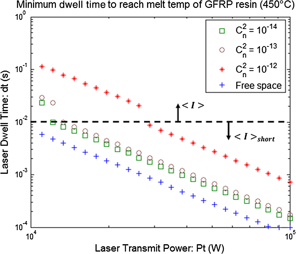
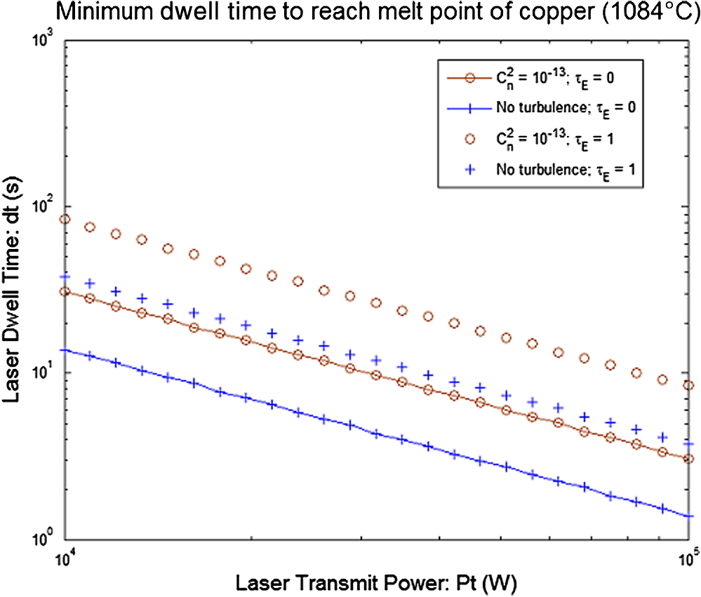
Equation (26) needs to be solved with boundary conditions. A commonly used approximate boundary condition is the Neumann condition: This is equivalent to zero heat flow across the boundary. This boundary condition is appropriate when the heat transfer from the solid object to the surrounding media is low (i.e., a relatively good thermal conductor in still air). The thermal time constant for a skin depth determines the approximate time required for heat generated by the conversion of laser energy in the skin depth region to diffuse a distance greater than the thickness of the skin-depth region. If the laser is incident on the target for a short time relative to the skin depth of the material the heat diffusion will be approximately given as follows:25When is in the range : Assuming heat has diffused out of the skin depth region, for relatively short times the heat will have not yet diffused far enough to reach the back surface of the metallic object located at . This time is determined by the thermal time constant as follows: In this time interval heat diffuses as it would in a semi-infinite metallic object, and a Neumann boundary condition is assumed at only. With this assumption, the temperature rise, , at is given by the following expression.25When is in the range : For relatively long times, the heat will have diffused through the thickness of the object, and a Neumann boundary condition assumed at both and . With these assumptions, the temperature rise, , at is given by the following expression.25When is in the range , 7.Numerical Examples7.1.Attenuation Due to TurbulenceWe consider a beam focused on a solid copper object of thickness . Figure 3 shows the predicted minimum laser dwell time required to heat the surface of the copper target to the melting point of copper using 10.6-µm radiation through a focused 5-cm aperture at 0.5 km. Although in practice it may be difficult to focus a laser at a distance of 0.5 km, we use the focused case to illustrate the worst-case degradation due to turbulence. The effect of turbulence on a collimated beam is less pronounced, and thus, the result will be closer to the free-space solution. The transmit power is varied from 10 to 100 kW, and various cases of atmospheric turbulence are considered: free space (no turbulence) and turbulence equal to , , and . For the thickness of copper and time range considered, Eq. (33) is used exclusively as heat has diffused a distance much greater than the thickness of the copper target. The plot in Fig. 3 can be used to predict the laser dwell time required to realize the onset of melting for a laser system of known transmit power. This result considers only when the absorbed power is sufficient to cause a sustained rise in temperature in excess of the melt temperature it applies generally to either pulsed or continuous wave (CW) operation, provided that the average power is held constant (e.g., 10 to 100 kW). In pulsed operation, the beam will have a higher power density, and thus, may cause a momentary spike in local temperature above the melt temperature, but during the off portion of the duty cycle the heat will diffuse out of the area and the temperature will decrease. Over many pulses the average temperature will rise at the same rate as a CW laser of equal average power. Figure 4 shows the predicted minimum laser dwell time required to heat the surface of a sample of Kapton (polyimide) target the glass transition temperature (400°C) using 10.6-µm radiation through a focused 5-cm aperture at 0.5 km. The transmit power is varied from 10 to 100 kW, and various cases of atmospheric turbulence are considered: free space (no turbulence) and turbulence equal to , , and . The discontinuity at is due to the inclusion of the fourth-order moment for short pulse durations as described in Sec. 3. For the thickness of polyimide and time range considered, Eq. (30) is used for , and Eq. (32) is used for . Figure 5 shows the predicted minimum laser dwell time required to heat the surface of a sample of water to its boiling point (100°C) using 10.6-µm radiation through a focused 5-cm aperture at 0.5 km. The transmit power is varied from 10 to 100 kW, and various cases of atmospheric turbulence are considered: free space (no turbulence) and turbulence equal to , , and . For the thickness of water and power ranges range considered, Eq. (30) is used exclusively as , which is greater than the maximum required laser dwell time to heat water to its boiling point. Figure 6 shows the predicted minimum laser dwell time required to heat the surface of a sample of GFRP to the melting point of polyester resin using 10.6-µm radiation through a focused 5-cm aperture at 0.5 km. The transmit power is varied from 10 to 100 kW, and various cases of atmospheric turbulence are considered: free space (no turbulence) and turbulence equal to , , and . For the thickness of GFRP and power ranges range considered, Eq. (32) is used exclusively as the required laser dwell times fall between and . 7.2.Attenuation Due to Turbulence and Atmospheric ExtinctionThe combined effect of atmospheric scattering and attenuation on a laser beam propagated through the atmosphere to a solid object target is a reduction in transmittance, which can, under the right conditions, become similar to or even greater in magnitude than the interference caused by atmospheric turbulence. Like the attenuation caused by atmospheric turbulence, the total extinction seen in a volume of atmosphere increases with the greater separation between the laser source and the target. This is easily deduced from Eq. (8), which contains the exponential attenuation term, . The product of extinction coefficient and linear distance is commonly called optical thickness: . An order-of-magnitude approximation is that the effect of atmospheric extinction should be considered when optical thickness . For a distance of 0.5 km this corresponds to . Figure 7 shows the effect of atmospheric extinction in this range on the laser dwell time required to heat a copper target to its melting point. Considering the free space (no turbulence) case, we can observe an increase in minimum laser dwell time when , which is in the range of the increase required in moderate turbulence. If optical thickness , then the increase in laser dwell time will be minimal, and if , then the effect of atmospheric extinction will dominate, and the relative effect of turbulence will be small. Figure 7 shows the effect of on laser propagation over 500 m. In real-world conditions, this value of atmospheric extinction is not typical when visibility is relatively good. According to Ref. 13, for visibility ranging from hazy to clear (5 to 40 km) atmospheric extinction remains below in a rural nonmaritime environment. According to Ref. 26, the atmospheric extinction coefficient for a maritime environment at 99% relative humidity is . In the presence of fog, however, when visibility can be reduced to 50 to 1000 m atmospheric extinction in the range can be expected. This is shown in a number of fog model calculations in Refs. 26 and 27. 8.ConclusionsThis paper presents a study on an optical beam propagated through turbulence and incident on various targets, generating heat and causing a temperature rise. The propagation of a beam wave in the atmosphere is discussed, including the fourth-order moment and the effect of thermal blooming. Transmitted power of 10 to 100 kW is absorbed in the target and converted into heat causing the temperature to rise. Numerical examples are given for 10.6 µm, free-space, and turbulence, aperture size , copper target thickness of 0.1 mm, Kapton target thickness of 0.1 mm, water thickness of 1 mm, and GFRP thickness of 10 mm. In each case, the beam is focused at 0.5 km, and the minimum laser dwell time required to heat the sample to its melting/boiling point is predicted. The effect of atmospheric extinction through absorption and scattering is discussed, and it is determined that the attenuation due to atmospheric extinction should be included in a dwell time calculation when . A plot is presented which shows the predicted difference in required dwell time for a focused laser through the atmosphere in zero and moderate turbulence with and . AppendicesAppendix:Proof for Absorbed Power EquationThe absorbed power-per-unit volume in the solid object target is given in Eq. (16). Likewise, the total absorbed power from to is given by If the integration path is sufficiently large, the total power is equal to the incident power minus the reflected power. This approach has been used in several papers including Refs. 16 and 17. In the case of thin objects and/or short integration paths, Eq. (34) gives the correct absorbed power. In this paper, we consider solid copper objects, and because the skin depth is small relative to object thickness, we can use Eq. (34) with . To prove equivalence, we can show that the incident power minus the reflected power is equal to Eq. (37), with .We start with the exact formulation: where and are the incident electric field and transmitted electric field, respectively, and where and are the characteristic impedances of free-space and object regions, respectively. From Eqs. (35) and (36), we can get the transmitted power: Taking the real part of Eq. (37), noting that , and that is purely imaginary, we get We note that ; ; ; ; and we get Using the expression for in Eq. (18), and evaluating Eq. (34) at, we get where and .Whereas the expression for transmitted power in Eq. (39) is derived from conservation of power and object interface boundary conditions, the expression for transmitted power in Eq. (40) is the total sum of the position dependent transmitted power given by Eq. (18). We can see that for objects where no energy transits the thickness of the object (i.e., object is thick relative to optical skin depth), these are equivalent. AcknowledgmentsThis work was supported by the Office of Naval Research (N000141110358) and the National Science Foundation (ECCS0925034). ReferencesS. Ackerman,
“Video: Navy Laser Sets Ship on Fire,”
(2011) http://www.wired.com/dangerroom/2011/04/video-navy-laser-sets-ship-on-fire/ March ). 2011). Google Scholar
L. AndrewsR. Phillips, Laser Beam Propagation Through Random Media, 321
–395 SPIE, Bellingham
(2005). Google Scholar
A. Ishimaru, Wave Propagation and Scattering in Random Media, 399
–452 Academic Press, New York
(1978). Google Scholar
P. SprangleJ. R. PenanoB. Hafizi,
“Optimum wavelength and power for efficient laser propagation in various atmospheric environments,”
Naval Research Laboratory, Washington, DC,
(2005). Google Scholar
P. SprangleJ. R. PenanoB. Hafizi,
“Propagation of intense short laser pulses in the atmosphere,”
Phys. Rev. E, 66
(4), 046418
(2002). http://dx.doi.org/10.1103/PhysRevE.66.046418 PLEEE8 1063-651X Google Scholar
J. R. Penanoet al.,
“Propagation of ultra-short, intense laser pulses in air,”
Phys. Plasmas, 11
(5), 2865
(2004). http://dx.doi.org/10.1063/1.1648020 PHPAEN 1070-664X Google Scholar
Z. H. Shenet al.,
“Mathematical modeling of laser induced heating and melting in solids,”
Opt. Las. Technol., 33
(8), 533
–537
(2001). http://dx.doi.org/10.1016/S0030-3992(01)00005-6 OLTCAS 0030-3992 Google Scholar
J. H. Betchel,
“Heating of solid targets with laser pulses,”
J. Appl. Phys., 46
(4), 1585
–1593
(1975). http://dx.doi.org/10.1063/1.321760 JAPIAU 0021-8979 Google Scholar
A. M. Prokhorovet al., Laser Heating of Metals, 39
–72 Adam Hilger/IOP, New York
(1990). Google Scholar
A. Ishimaru,
“The beam wave case and remote sensing,”
Laser Beam Propagation in the Atmosphere, 129
–170 Springer-Verlag, New York
(1978). Google Scholar
S.F. Clifford,
“The classical theory of wave propagation in a turbulent medium,”
Laser Beam Propagation in the Atmosphere, 9
–43 Springer-Verlag, New York
(1978). Google Scholar
B. J. Lund,
“Laser atmospheric attenuation tables for LTAS,”
(1997). Google Scholar
P. A. Fredericksonet al.,
“Estimating the refractive index structure parameter over the ocean using bulk methods,”
J. Appl. Meteor., 39
(10), 1770
–1783
(2000). http://dx.doi.org/10.1175/1520-0450-39.10.1770 JAMOAX 0894-8763 Google Scholar
J. L. WalshP. B. Ulrich,
“Thermal blooming in the atmosphere,”
Laser Beam Propagation in the Atmosphere, 223
–320 Springer-Verlag, New York
(1978). Google Scholar
M. A. Ordalet al.,
“Optical properties of fourteen metals in the infrared and far infrared: Al, Co, Cu, Au, Fe, Pb, Mo, Ni, Pd, Pt, Ag, Ti, V, and W,”
Appl. Opt., 24
(24), 4493
–4499
(1985). http://dx.doi.org/10.1364/AO.24.004493 APOPAI 0003-6935 Google Scholar
X. E Lin,
“Laser pulse heating,”
in Proc. Particle Accelerator Conf.,
1429
–1431
(1999). Google Scholar
S. B. BoydenY. Zhang,
“Temperature and wavelength-dependent spectral absorptivities of metallic materials in the infrared,”
J. Thermophys. Heat Trans., 20
(1), 9
–15
(2006). http://dx.doi.org/10.2514/1.15518 JTHTEO 0887-8722 Google Scholar
S. G. WarrenR. E. Brandt,
“Optical constants of ice from the ultraviolet to the microwave: a revised compilation,”
J. Geophys. Res., 113 D14220
(2008). http://dx.doi.org/10.1029/2007JD009744 JGREA2 0148-0227 Google Scholar
Z. M. Zhanget al.,
“Infrared refractive index and extinction coefficient of polyimide films,”
Int. J. Thermophys., 19
(3), 905
–916
(1998). http://dx.doi.org/10.1023/A:1022655309574 IJTHDY 0195-928X Google Scholar
R. Komanduri,
“Machining of fiber-reinforced composites,”
Mach. Sci. Technol., 1
(1), 113
–152
(1997). http://dx.doi.org/10.1080/10940349708945641 MSTEFW 1091-0344 Google Scholar
R. KitamuraL. PilonM. Jonasz,
“Optical constants of silica glass from extreme ultraviolet to far infrared at near room temperature,”
Appl. Opt., 46
(33), 8118
–8133
(2007). http://dx.doi.org/10.1364/AO.46.008118 APOPAI 0003-6935 Google Scholar
E. D. PalikG. Ghosh, Handbook of Optical Constants of Solids, 957
–987 Academic, New York
(1998). Google Scholar
L. TsangJ. A. KongK. H. Ding, Scattering of Electromagnetic Waves, 351
–353 Wiley, New York
(2001). Google Scholar
“DuPont Kapton Polyimide Film Datasheet,”
(2013) http://www.dupont.com/kapton/general/H-38479-4.pdf March ). 2013). Google Scholar
M. Sparks,
“Theory of laser heating of solids: metals,”
J. Appl. Phys., 47
(3), 837
–849
(1976). http://dx.doi.org/10.1063/1.322717 JAPIAU 0021-8979 Google Scholar
E. P. ShettleR. W. Fenn,
“Models for the aerosols of the lower atmosphere and the effects of humidity variations on their optical properties,”
(1979). Google Scholar
C. Reinhardtet al.,
“Atmospheric channel transfer function estimation from experimental free-space optical communications data,”
Opt. Eng., 51
(3), 031205
(2012). http://dx.doi.org/10.1117/1.OE.51.3.031205 OPEGAR 0091-3286 Google Scholar
BiographyMatthew Stoneback received his BS and MS in electrical engineering from the University of Washington in 2008 and 2009, respectively. From 2007 to 2011, he was an intern and engineer with Boeing Research and Technology in Seattle, WA. He is currently pursuing a PhD in electrical engineering at the University of Washington. His interests are in the areas of antennas, phased arrays, electromagnetic propagation, and optics. Akira Ishimaru received his BS in 1951 from the University of Tokyo, and PhD in electrical engineering in 1958 from the University of Washington. From 1951 to 1952, he was with the Electrotechnical Laboratory, Tokyo, and in 1956 he was with Bell Laboratories, New Jersey. In 1958, he joined the faculty of the Department of Electrical Engineering of the University of Washington, where he was professor of electrical engineering and adjunct professor of applied mathematics, and is currently professor emeritus. He was also a visiting associate professor at the University of California, Berkeley. His current research includes waves in random media, remote sensing, object detection and imaging in clutter environment, inverse problems, millimeter wave and optical propagation and scattering in the atmosphere and the terrain, acoustic scattering in the ocean, ultrasound imaging, and optical diffusion in tissues. He is the author of Wave Propagation and Scattering in Random Media (Academic Press, 1978; IEEE Press-Oxford University Press Classic Reissue, 1997) and Electromagnetic Wave Propagation, Radiation, and Scattering (Prentice Hall, 1991). Colin Reinhardt received his BSEE and BS in physics from the University of Washington in 2005, and PhD from University of Washington in 2010, as an American Society for Engineering Education and Department of Defence (ASEE-DoD) Science, Mathematics, and Research for Transformation (SMART) Fellow. He now works at SPAWAR Systems Center Pacific, in San Diego, California, with the Atmospheric Propagation Branch. His interests include electromagnetic wave propagation in random media, free-space optical communications, multiple-scattering theory, radiative transfer theory, optical turbulence, and communications theory. Yasuo Kuga was received his BS, MS, and PhD degrees from the University of Washington, Seattle, in 1977, 1979, and 1983, respectively. He was an engineer at Matsushita Electric Industrial Corporation, Osaka, Japan, from 1971 to 1975. From 1979 to 1983, he was a research associate at the University of Washington. From 1983 to 1988, he was a research assistant professor of electrical engineering at the University of Washington. From 1988 to 1991, he was an assistant professor of electrical engineering and computer science at the University of Michigan. He is now professor of electrical engineering at the University of Washington. His research interests are in the areas of microwave and millimeter-wave remote sensing, high-frequency devices, and optics. |