|
|
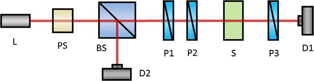
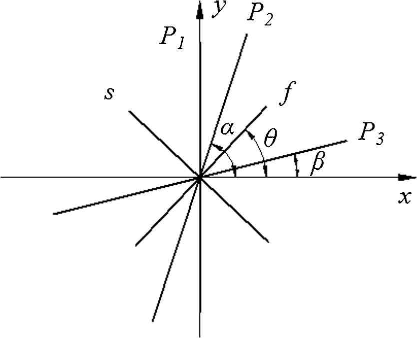
1.IntroductionBirefringence is an important property of optically anisotropic materials. Most isotropic solids also exhibit birefringence under mechanical stress. The residual stress in optical glass will produce birefringence, which decrease the performance of optical system. Thus the measurement of birefringence is important for optical glass. Phase-shifting methods1 are well-known to be the most effective ways in whole-field or point-scanning measurements for birefringence. They generally fall into three categories: the methods based on plane polariscope,2–6 Senarmont polariscope,7 and circular polariscope.8–11 The latter two categories should take use of quarter-wave plates, which will introduce major errors and additional dependence on both temperature and wavelength, while the first class has the simplest optical setup and also no errors from quarter-wave plates. However, the previously proposed plane-polariscopic methods—such as the three-step2 and six-step5 methods, multiwavelength methods,3,4 and spectropolarimetric method6, did not take into account the fluctuations of incident light. When laser is used as the light source, the fluctuations of both output intensity and polarization state of the laser will produce significant adverse effects on the measurement, and should be rigidly considered. In this paper, we report for the first time a simple four-step phase-shifting method based on a triple-polarizer plane polariscopic arrangement. This method works with greatly reduced influences from the light fluctuations of both an intensity and polarization state. It is also a nearly achromatic method since no wavelength-dependent wave plates are used. 2.MethodFigure 1 schematically shows the optical setup of proposed method. In Fig. 1, is the light source, PS is the polarization stabilizer, BS is the beam splitter, P1 is a fixed linear polarizer, P2 and P3 are the rotatable linear polarizers, is the sample under test, D1 and D2 are the photo detectors. The relative orientation angles between the principal axes of three polarizers, the sample, and the coordinates are shown in Fig. 2. In our method, the azimuth angle of the fixed polarizer is set to be 90 deg, while the polarizers P2 and P3 will take angles denoted by and , respectively, with respect to the -axis. In Fig. 2, the and stand for the fast and slow axis of the sample. Assuming that the azimuth angle of sample is , and the phase retardation of sample is . The polarization state of the incident light on P1 can be represented by Stokes vector ,12 where , , and should be constants since the stabilities of intensity and polarization state of the incident light are vital in the process of phase-shifting. Now applying the Mueller calculus,12 one can obtain the general expression of the intensity of light emerging from P3 where , , and are the constant intensity transmittances of linear polarizers P1, P2, and P3 on their principal axes, respectively, and is the constant intensity transmittance of the sample under test. We assume the linear polarizers are ideal diattenuators and the sample is a pure phase retarder. To determine the unknowns and , we change the angular positions and , and obtain the intensity equations on D1, as shown in Table 1. To simplify notation let .Table 1Output intensity of P3 at four angular positions for P2 and P3.
Obviously from Table 1 one can eliminate the unknown constants , , and find the solutions of and , which are The range of calculated phase retardation from Eq. (2) is limited to . Fortunately, for the case of applications on optical glass, the stress-induced phase retardation is rarely larger than . From Eq. (3), it appears that the range of azimuth angle is . But we can extend it to the full range (i.e., ) of the measured azimuth angle on the plane polariscope by the following algorithm, as shown in Table 2.Table 2The method to extend the range of θ.
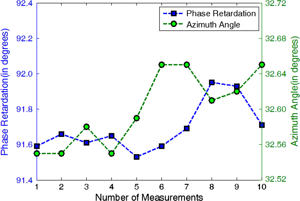
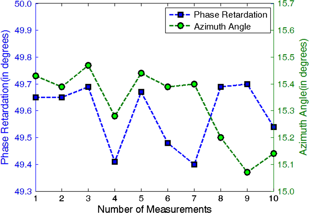
It should be noted that the Stokes parameters and in Eq. (1) must keep constant so that they can be totally eliminated in the process of phase-shifting. However, if laser is used as the light source, its output intensity and polarization state may drift significantly in the process of measurement. Also, the unstable polarization state of the light will affect to some extent the split ratio of beam splitter, even if it is a nonpolarizing beam splitter, which will ultimately introduce additional error into the correction for intensity stabilization. Hence a polarization stabilizer should be employed to keep the polarization state of light invariable. The second detector D2 is employed to enable intensity correction. In addition, unlike previously proposed algorithms,9–11 the phase retardation is determined independently of the evaluated azimuth angle by Eqs. (2) and (3). 3.Experiment and ResultsIn the experimental system, the calcite Glan-Thompson prisms (LGP-1A10, China), which offer extinction ratios of approximately are used as the three polarizers P1 to P3. P1 is fixed with a 90-deg angle of polarization axis, while P2 and P3 are mounted on the motorized rotation stages with limiting angular errors of less than 5 arcmin. The light source is a collimated laser diode module (Thorlabs, CPS180). The output light from P3 is detected by the detector D1 (Thorlabs, PDA36A) and digitized by a 16-bit DAQ device (Measurement Computing, USB-1608FS). Also, a fixed high-grade polarizer (LGP-1A10) is utilized as the polarization stabilizer, which is expected to generate stable linear polarized state, and a second detector D2 (Thorlabs, PDA36A) is employed to correct the intensity fluctuation of the laser light. The remnant random fluctuation of intensity is further minimized by resorting to time averaging in data acquisition. The experimental system is automatically controlled by Labview™ (NI) software. To demonstrate the validity of the above-described method, numerical analysis is first carried out. Supposing the sample has a phase retardation of 90 deg with the azimuthal angle of 15 deg. The standard deviations (std) of angular positions of P2 and P3 are 2 arcmin (normal distribution). The extinction ratios are , and intensity transmittances along the principal axes are 0.9 for all polarizers. We also introduce a discretization error of 1‰ into the A/D process. Taking Stokes parameters of the stabilized input light on P1 to be (1.0, , 0.1736, 0), we will obtain 89.748 deg (mean) and 0.302 deg (std) for phase retardation, and 14.925 deg (mean) and 0.029 deg (std) for azimuthal angle after a thousand of calculations. Additionally, if we introduce a misalignment error of for P1 and P3, we will get 90.157 deg (mean) and 0.226 deg (std) for phase retardation, and 15.149 deg (mean) and 0.038 deg (std) for azimuthal angle. We carried out the experiments in darkroom to reduce the environmental effects as possible. Also the background intensity is initially obtained before measurement and then removed in data processing. The nonlinearities of the detecting and data acquisition system are also carefully inspected and found to be less than 1%. Two mica wave plates are tested as samples. We carried 10 measurements for each sample and the experimental results are shown in Figs. 3 and 4, respectively. For the case of sample 1, the mean and standard deviation (std) of measured phase retardation are 91.69 deg and 0.14 deg, respectively, which agrees well with our previous results.13 The std of measured azimuth angle is 0.042 deg. So it is demonstrated that this triple-polarizer phase-shifting method shows good accuracy and excellent repeatability in the birefringence measurement. For sample 2, the mean and std of phase retardation are 49.59 deg and 0.12 deg, respectively, and the std of measured azimuth angles is 0.14 deg. Excellent repeatability is obtained as well in this case. 4.ConclusionsThe four-step phase-shifting method for birefringence measurement based on the triple-polarizer plane polariscopic setup has been presented and demonstrated experimentally. The measurement ranges for phase retardation and azimuth angle are and , respectively. Good experimental repeatabilities on both phase retardation and azimuth angle are demonstrated. This method holds several advantages: simple setup, no use of wave plates, free from the errors of wave plate, wavelength independence, ease of alignment. AcknowledgmentsThe work is supported by the basic research foundation of Beijing Institute of Technology (3040012211105), China. ReferencesK. Ramesh, Digital Photoelasticity, Advanced Techniques and Applications, Springer-Verlag, Berlin
(2000). Google Scholar
A. V. Sarmaet al.,
“Computerized image processing for whole-field determination of isoclinics and isochromatics,”
Exp. Mech., 32
(1), 24
–29
(1992). http://dx.doi.org/10.1007/BF02317980 EXMCAZ 0014-4851 Google Scholar
A. D. Nurse,
“Full-field automated photoelasticity by use of a three-wavelength approach to phase stepping,”
Appl. Opt., 36
(23), 5781
–5786
(1997). http://dx.doi.org/10.1364/AO.36.005781 APOPAI 0003-6935 Google Scholar
P. PinitE. Umezaki,
“Digitally whole-field analysis of isoclinic parameter in photoelasticity by four-step color phase-shifting technique,”
Opt. Laser Eng., 45
(7), 795
–807
(2007). http://dx.doi.org/10.1016/j.optlaseng.2006.12.005 OLENDN 0143-8166 Google Scholar
X. ZhangL. ChenC. He,
“Phase-stepping method for whole-field photoelastic stress analysis using plane polariscope setup,”
Proc. SPIE, 7656 76565B
(2010). http://dx.doi.org/10.1117/12.867949 PSISDG 0277-786X Google Scholar
A. SafraniI. Abdulhalim,
“Spectropolarimetric method for optic axis, retardation, and birefringence dispersion measurement,”
Opt. Eng., 48
(5), 053601
(2009). http://dx.doi.org/10.1117/1.3126628 OPEGAR 0091-3286 Google Scholar
L. ZhangD. ShaL. Nie,
“Whole-field digital measurement of the stress isoclinic parameter of optical glass based on phase shifting,”
Optical Technique, 30
(2), 199
–203
(2004). Google Scholar
T. W. Ng,
“Derivation of phase in computer-aided photoelasticity,”
Opt. Lett., 20
(7), 669
–670
(1995). http://dx.doi.org/10.1364/OL.20.000669 OPLEDP 0146-9592 Google Scholar
J. A. QuirogaA. González-Cano,
“Phase measuring algorithm for extraction of isochromatics of photoelastic fringe patterns,”
Appl. Opt., 36
(32), 8397
–8402
(1997). http://dx.doi.org/10.1364/AO.36.008397 APOPAI 0003-6935 Google Scholar
A. AjovalasitS. BaroneG. Petrucci,
“A method for reducing the influence of quarter-wave plate errors in phase stepping photoelasticity,”
J. Strain Anal. Eng. Des., 33
(3), 207
–216
(1998). http://dx.doi.org/10.1243/0309324981512922 JSADDZ 0309-3247 Google Scholar
S. BaroneG. BurriesciG. Petrucci,
“Computer aided photoelasticity by an optimum phase stepping method,”
Exp. Mech., 42
(2), 132
–139
(2002). http://dx.doi.org/10.1007/BF02410874 EXMCAZ 0014-4851 Google Scholar
D. H. Goldstein, Polarized light, Marcel Dekker Inc., New York
(2003). Google Scholar
X. ZhangH. WangC. He,
“Analysis on the effect of extinction ratio in birefringent measurement by phase-stepping method,”
Proc. SPIE, 8557 85572E
(2012). http://dx.doi.org/10.1117/12.999274 PSISDG 0277-786X Google Scholar
|