|
|
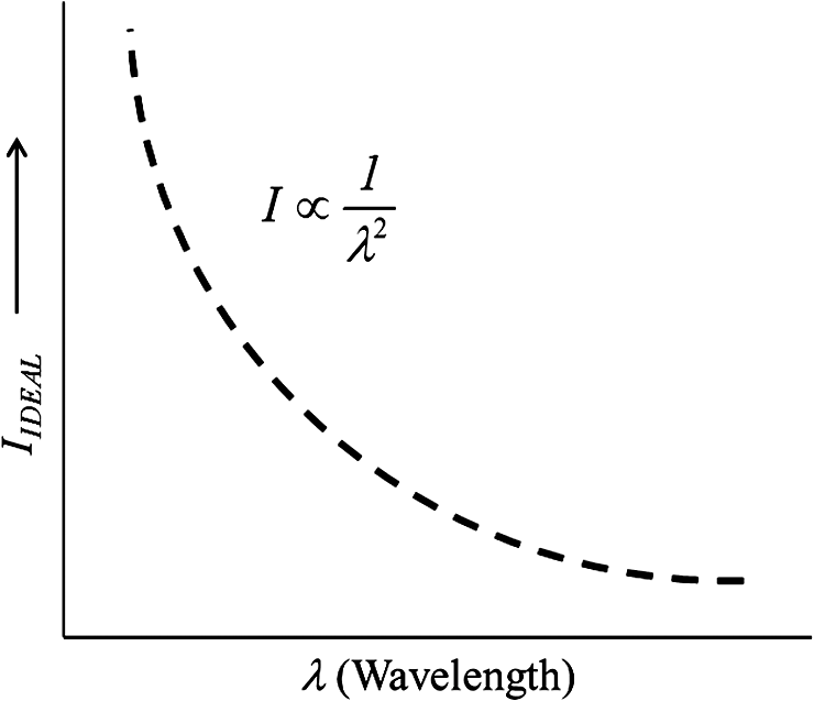
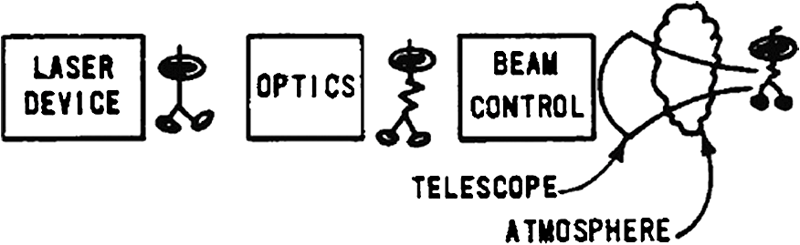
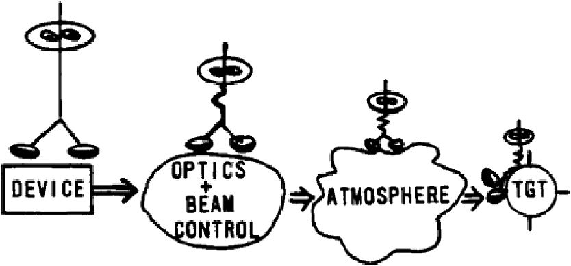
1.IntroductionThe brightness potential of a laser is inversely proportional to the square of its wavelength. Short wavelength lasers (SWLs), which I define as having a wavelength () of less than , or, 2 μm, have an enormous potential for achieving high brightness with an accompanying reduction of power or telescope size. This compactness can lead to weight/volume reductions, which both enhance mission feasibility and reduce costs. Once a SWL with good beam quality (BQ) is identified, then beam control becomes the key to success. Challenges abound! As the laser wavelength decreases, the phase aberration “bumps” in the beam path: man-made, natural and beam induced—become dramatically more important. In general, energy is scattered from the beam, and the beam itself is deflected. The result is a reduction in far field intensity. This latter parameter is defined as the beam power per unit area that can be projected onto a target. I will refer to this as “flux-in-a-bucket”. Generally, it has units of . To produce a nearly pristine beam at the target, careful photon management must be accomplished from “A to Z”. Both passive and active beam control are essential. Passive techniques include high quality optics (precise figure, smoothness) and a near diffraction-limited SWL device. Active techniques could include mechanical or nonmechanical adaptive optics (AO). By applying this to the entire photon odyssey, one can achieve high-brightness SWL systems. The path is rough, but the payoff is prodigious! Let us now begin our photon odyssey …in search of short wavelength high brightness laser systems. First we introduce the guides. Freddy the Photon will show us the many obstacles he faces in getting from SWL laser device to the target. His companion, Felix the Flux, represents many SWL photons. Both appear in Fig. 1. These will serve as our animated guides as we trek through the SWL “photon foxholes.” Our quest for high brightness laser systems starts at the source …the laser device. Source brightness is where is power , is the BQ, is the wavelength ; brightness is traditionally defined as , where A is the system’s telescope clear aperture area.Of the several paths to higher source brightness, increasing power is the least attractive! Reasons include:
If a SWL laser, wavelength , is magnified and focused on a target at distance , then the ideal intensity delivered is where is again the telescope aperture area and is system absorption plus atmospheric and aero-optic scattering losses. Equation (2) is the ideal laser system peak far-field intensity, or Strehl. The larger the more lethal the system becomes. A SWL can achieve this lethality more easily (e.g., less power, smaller telescope size) than longer wavelength systems.Before leaving this ideal situation, let’s note the potential payoff of SWLs. For example, a reduction in wavelength from (deuterium fluoride chemical laser) to (excimer laser), with all other parameters in Eq. (2) being identical, yields a brightness increase of 100 for the SWL Excimer laser system! This wavelength dependence of is shown in Fig. 2, and graphically shows the lure of SWL systems! 2.Cost of SWL SystemsRecent data from the Air Force Weapons Laboratory’s (AFWL) Chemical Oxygen-Iodine Laser (COIL) suggests that the cost scaling for telescope aperture is so that the costs, , of some SWLs should scale as , where the premultipliers and are constants. The SWL system brightness is just source brightness times telescope aperture, or and setting , we find*For example, for constant brightness, a factor of 4 reduction in results in a 75% cost savings (e.g., 2 μm system versus 0.5 μm). Alternately, given SWL can be scaled an order of magnitude in brightness for a cost growth factor of . 3.Challenge of Achieving SWL High BrightnessThe path to SWLs is paved with phase aberrations or “bumps”. As the laser wavelength decreases, the bumps in the beam path magnify in importance. A real SWL laser system suffers from three classes of aberrations.
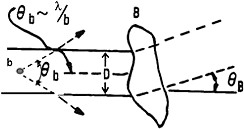
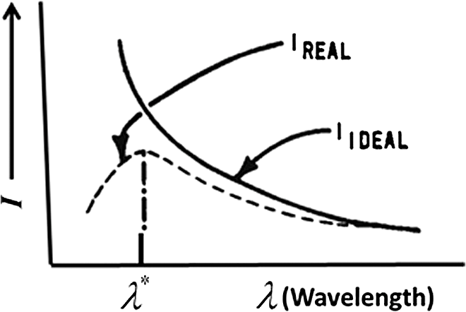
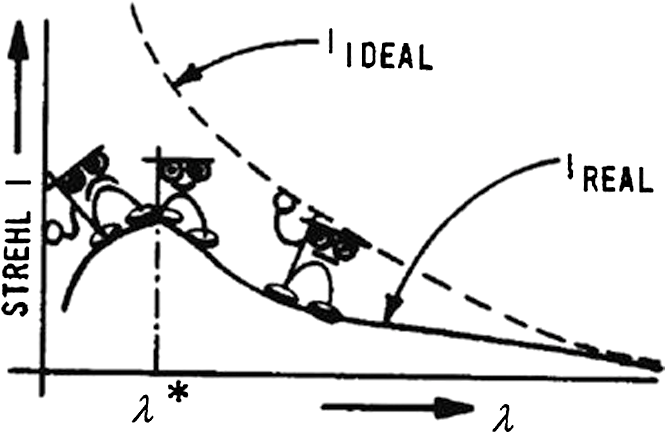
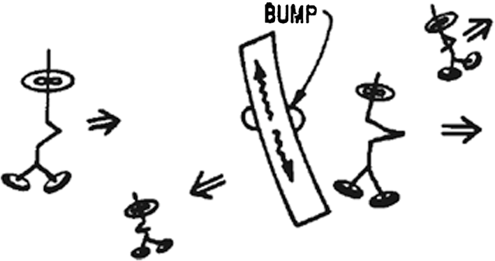
As our laser beam conducts its photon odyssey from device to target, it encounters a veritable blizzard of phase “bumps,” each varying in strength and size. The result can be a beam which is jittered, spread, and markedly reduced in peak intensity. While careful photon management can alleviate these effects, ideal performance, Eq. (2), is not achievable. To understand how these phase aberrations affect the laser beam, we note that “bumps” can be placed in two classes—those small compared with the beam diameter D and those larger than D. Figure 3 shows these two classes. The small phase aberration, size , scatters photons at characteristic angle . The amount of scatter depends on both the strength and dimensions of the bump. This strength scales as the difference in refractive index between the bump and its surroundings. The larger phase bump acts to steer the entire beam over angle dependent on refractive index, but not wavelength. Phase bumps sizes between and can be expressed as a combination of the two extremes. The result of our SWL photon odyssey is a far-field beam suffering a marked reduction in intensity because of scatter and beam spread. We write this as where is the system jitter (tip/tilt) and is the system root mean square (RMS) phase variance.Equation (4) consists of three parts. The term in brackets at the end of the equation is just the ideal brightness, [Eq. (2)]. The exponential term reflects losses due to wide angle scattering (i.e., phase bumps small compared with beam diameter). Finally, the term in front brackets expresses reduction in brightness because of beam jitter (recall this last aberration is driven by bumps larger than the laser beam or by system mechanical vibrations). Figure 4 compares and . It shows the quintessential challenge of SWL systems. For convenience, we set (actually, atmospheric absorption/scatter shows a strong wavelength dependence. In practice, for applications requiring propagation through the atmosphere, one picks a laser whose wavelength(s) fall in a transmission “window”). Note the following:
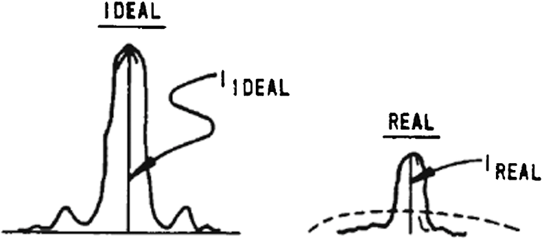
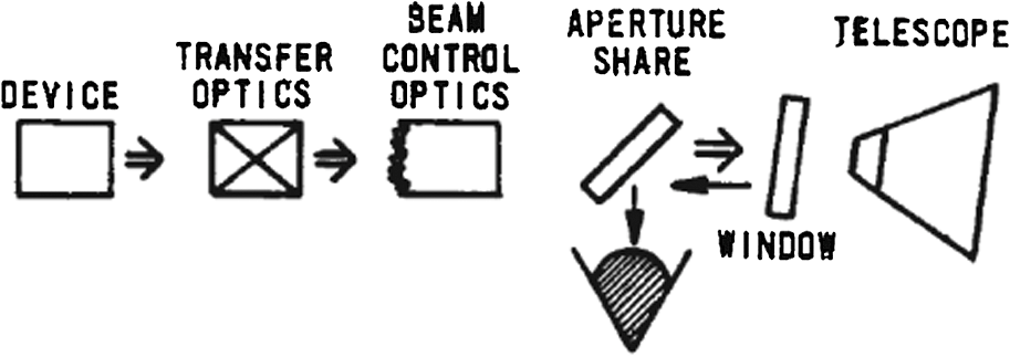
Figure 5 depicts the major components of a laser system. Figure 6 shows Freddy’s quest for SWL high brightness. To realize the potential of our SWL system, one must meticulously orchestrate the photons to enable a high BQ beam to arrive at the target. Much as a conductor brings harmony to a collection of independent musical instruments, so must the laser system engineer orchestrate Freddy through the system, which includes a mine field of “jitters” and high order phase aberrations. A high quality SWL is the door to very high brightness laser systems. The lock is system phase aberrations—natural, man-made and laser beam produced—that act to dramatically reduce BQ. Beam control is the key, which if used creatively and coherently, can open the door to high brightness SWLs. Note that for a given set of (uncorrected) aberrations, the system Strehl performance actually decreases for . The effects of these uncorrected phase aberrations on far field performance are shown in Fig. 7. Our ideal beam is shown for reference. The real beam at the target consists of a central unaffected spot and a “halo” of energy due to aberration-induced beam jitter and spread. The resulting beam is markedly reduced from the ideal in both peak intensity and “flux-in-the- bucket”. Again the challenge of beam control is to bring the real SWL performance close to the ideal. The path to a high brightness, SWL system is very difficult; first, a high quality SWL laser must be identified. Then, principal challenges are the many optical train phase aberrations that magnify rapidly with reduced wavelength, and if uncorrected, can emasculate system far-field performance. The premier key to success is beam control. Careful photon management is essential to realizing the potential of high brightness SWL systems. The second key to success is also beam control!! The remainder of this paper will describe the photon odyssey from device to target. First, some general features of laser systems will be broached. The various sources of optical phase aberrations, man-made, natural, and laser-induced will be examined. Next, effects on the optimum laser wavelength because of wide-angle scatter, beam spread and nonlinear will be plumbed. We will see that each uncorrectable source of phase aberration causes significant reductions in Strehl, or far-field performance. AO techniques have the potential to correct certain system aberrations, and so recover some Strehl. However, today’s mechanical AO systems are cumbersome and costly. Nonlinear optical (NLO) methods will be presented as offering a quantum breakthrough in SWL beam control! How a given SWL laser system scales in brightness will be studied. After noting that monolithic systems (i.e., single laser/telescope) have brightness limitations …because of either engineering or physics constraints …we will examine how lasers and telescopes can be coupled to yield very high brightness systems. If such systems can be rendered highly coherent, their performance will be close to that of a monolith having the same equivalent power and telescope aperture area. Conclusions drawn in comparing these exciting approaches are based wholly on basic physics and the arguments I will develop in this paper. 4.General Laser System FeaturesLasers have several intrinsic advantages as weapons systems:1
Some disadvantages of lasers:
In fact, blending lasers and kinetic energy weapons can yield synergy:
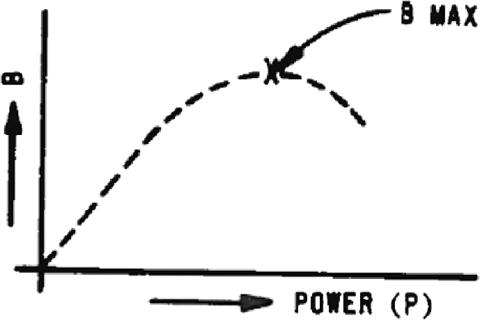
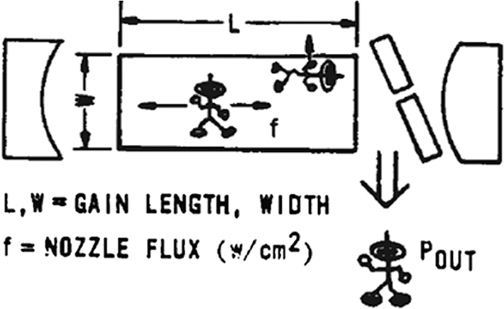
Recall the device ideal brightness in Eq. (1) is . Table 1 summarizes demonstrated performance of several extant lasers. Table 1Demonstrated performance of several extant lasers. 5.Laser Device ScalingA monolithic laser system consists of a single device and telescope. Such a system has a brightness “ceiling” established via either physics or engineering limitations. I refer to this “biggest monolith with good BQ” as the unit cell. As this single device is power scaled, energy management becomes more difficult, leading eventually to intrinsic loss of BQ or extrinsic optics damage from the increasing beam flux. Thus, a monolithic laser system has a maximum brightness Attempting to increase power beyond this value can actually cause system brightness to decrease! Figure 8 shows brightness saturation for a single SWL. Further power scaling requires coupling lasers together. Such has been demonstrated for lasers by the Strategic Defense Initiative Organization and the AFWL. We, at the AFWL recently showed coupling for oxygen-iodine () lasers, and plan near term similar experiments for excimer lasers. As a single laser module grows, three effects combine to degrade BQ per Fig. 9.
These effects act either individually or in concert to limit the maximum brightness of a unit cell. Now, let’s review the physics that sets the size of the unit cell. The power in the laser cavity (Fig. 9) is just , with (). From Eq. (5), system brightness, , is proportional to and , where is the system beam (power)-induced RMS phase aberrations (note that , where is the density variance in the lasing direction). Now observe from the above relation that power scales linearly but n grows exponentially! Thus, beam brightness saturates and eventually decreases! Every monolith or unit cell has scaling limits! At modest powers because the BQ is approximately constant; however, as the laser cavity volume expands, BQ degrades rapidly. Thus, brightness will eventually be limited by BQ degradation. A second concern is the effects of growing cavity flux on resonator optics. As an example, consider likely scaling limitations for an unit cell. Our 30 kW, in-house (COIL) demonstration suggests that if linear scaling is operative, a high quality megawatt-class is plausible! BQ degradation will become significant eventually (perhaps in the regime); even so, a closed-loop AO system could in principle recover some performance. Low order variations in refractive index, e.g., tilt and focus, can be corrected in the resonator; however, higher order (HO) corrections require a complete AO system. This, then, would leave us with a structures limitation—cavity optics distortion/damage. This threshold might be realized in the 5 to 10 MW range. Thus, based on simple scaling laws and a 30 kW demonstrator, the unit cell can probably be scaled to the multi-MW regime while retaining good BQ (via AO corrections). Further power scaling requires coherently lashing together multiple lasers. A monolithic SWL system has a power scaling ceiling, beyond which system performance degrades to unacceptible levels. Expanding the device cavity volume eventually results in markedly reduced BQ—from flux induced aberrations or structural/optical damage. Once a maximum achievable “unit cell” brightness is known, further scaling requires coupling together multiple cells or laser systems. The oxygen-iodine () laser has been scaled to with excellent BQ by the AFWL. Projections suggest that a high quality laser in the several megawatt milieu is feasible. 6.Relay Optics: Orchestrating the Beam from the Device to the AtmosphereRelay optics transport the high power (HP) laser beam from the device to the projecting telescope. For example, windows may be used to accommodate a pressure drop (e.g., device cavity to ambient). A HP beam transmitting such a window will suffer absorption in both the coating and the bulk—and will result in thermal distortion of the window with subsequent phase aberrations imposed on the HP beam. Similarly, reflective optical flats, AO, aperture sharing elements (ASE)—cooled or uncooled—plus a telescope are required. Figure 10 shows an optical suite which, of course, must operate in harmony to deliver a high quality beam to the target. We next plumb performance of these vital components in transporting a HP SWL beam. 7.SWL Windows: a Critical ElementWindows are crucial to SWL systems to either:
Two kinds of windows have been developed for HP lasers—aerodynamic and material. Aerodynamic windows use a high velocity gas sheath across the laser port which is to be “sealed”. A pressure differential is established to insulate the “inside” from the “outside,” with and the shear layer density and velocity, respectively. There are two major disadvantages:
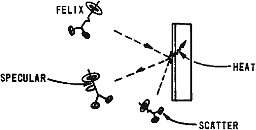
Aero windows are impractical for HP SWL systems. The highly-turbulent shear layers result in strehl losses of a few tens of percent per window; This both markedly reduces system brightness and causes potentially severe laser energy scattering within the optical train. Plan “B” for our SWL system is a material window. This window generally has an antireflective (AR) coating to minimize reflections from the surfaces. Though such coatings are generally only wavelengths thick, laser energy is absorbed in both the coating and bulk material. Figure 11 shows a laser beam incident on our window. This beam generally has a nonuniform intensity profile, as shown by the notch in “Felix the Flux.” One of five events can occur to each photon:
On a microscopic scale, hot spots are formed within our window due to absorption of a nonuniform incident beam. Each little temperature causes index of refraction and window thickness changes. Each Freddy the Photon, in turn, has a different optical path, resulting in a phase shift across the beam. The emerging beam is complex, with window-induced nonuniformities in both intensity and phase. We estimate the resulting Strehl loss from where is the window-induced RMS phase variance, and where () is the optical distortion coefficient and is the window thickness. Now the optical distortion coefficient may be either positive or negative, but a typical SWL window (e.g., ) is . This assumes that the intrinsic window stresses are small; if not, the Strehl loss will generally be even greater!Cooling SWL windows will be a tough challenge! Edge cooling is generally ineffective. A novel advanced technique streamed an index-matched coolant through the bulk window. This is promising—but quite untested! Very thin material membranes have been examined as candidate windows, and have been shown to have low absorption under intense laser beam loading. However, these “pellicles” suffer from two disadvantages:
Development of a material window is a crisp challenge for an SWL system. Material windows must have extremely low absorption and good intrinsic quality. Most windows require coatings for energy management; these can have absorption levels of the same order as the window itself! Coatings also act to scatter photons leading to sensor or structural damage. Beam-induced temperature variances of order 1 k are sufficient to cause over a 50% strehl loss from a single window! Convective cooling can mollify surface effects, but is ineffective for window bulk absorption. Advanced cooling techniques, such as low absorption, laminar index matched flow through bulk window are approaching HP proof-of-principle testing at the AFWL. Cooling techniques are probably essential for high brightness SWLs and are unproven! The development of very low absorption, cooled windows is a prerequisite to fielding many high brightness SWL systems. 8.SWL High Power Mirrors: an Important ElementElements in this suite include device cavity and transfer optics, deformable mirrors (DMs), beam steering mirrors and the telescope. Each mirror generally has applied a highly reflecting (HR) coating, tailored to the laser wavelengths(s). Most HP applications demand reflectivities well above 99%. Figure 12 shows our beam impinging on a mirror. Four outcomes are possible for each photon:
Mirrors may be cooled or uncooled; however, because no laser energy is transmitted, heat exchanger (HEX) technology can be effectively used to minimize beam intensity mapping effects. Beam-induced aberrations are generally significantly less than that of windows. However, cooled optics present two principal difficulties:
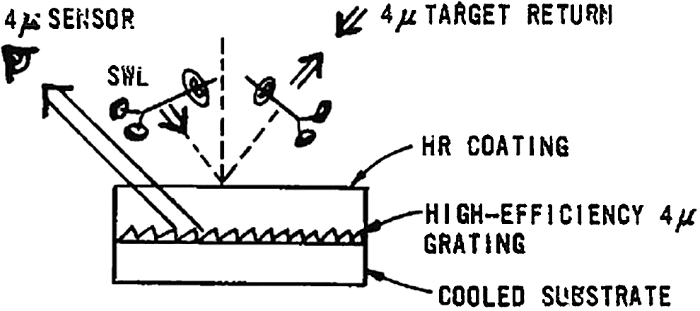
A quantum advance may be in the offing as a result of low-flow HEX research sponsored by the AFWL over the past two to three years! Traditional HP HEXs use metal (e.g., molybdenum) face sheets with high coolant pressures/flow rates. Distortion coefficients are typically . For example, an absorbed laser intensity of would result in faceplate distortion of for a SWL! Corresponding coolant flows are . Our low flow HEX concept uses a thin () ULE (glass ceramic) face sheet! The distortion coefficient of ULE is only—! Moreover, the lower flow rate—about yields near laminar flow condition. Most importantly for SWL systems, the flow-induced jitter for low flow HEX is that of “traditional” HP HEXs. Although power handling capabilities of this advanced concept is somewhat less, it is still highly attractive for several potential SWL applications. SWL mirrors are a vital element of any high brightness SWL system. Development risks are moderate. HP mirror technology is more mature than HP window technology! Because our mirrors can use efficient HEX technology, beam induced phase distortions in the optic can generally be controlled. If an active HEX is required, cost and coolant induced jitter become important factors. The development of simple, efficient low flow HEX is an important step to realizing HP SWL systems. Such a concept has been developed at the AFWL which marries a thin ULE facesheet with a laminar flow ULE HEX. This promises a low-jitter/HP handling capability which could be a major advance for SWLs 9.SWL Aperture Sharing Elements: a Crisp ChallengeMany high brightness SWL systems require an ASE (material window is an implausible candidate, as noted earlier). This element separates the outgoing (HP) laser beam from the target-return tracking beam (e.g., an active—4 μm laser tracker). Figure 13 shows a simple buried grating. Its task is to efficiently reflect a HP SWL while directing an axial incoming (low power) tracker return to a suitable sensor array. There are strong motivations from all beams sharing the same optical axis—boresiting is automatic, and beam control, in the presence of misalignments, jitter or high order aberrations is greatly simplified. The downside is the knotty optical engineering challenge of developing an ASE. The HP SWL reflects from the HR front surface. The target return laser beam ( to 10 μm) is diffracted by the grating to the tracker sensor. The challenge is not building such ASEs—but in managing the thermal energy from the HP SWL that is absorbed at the front surface and/or the bulk (if the uncooled substrate is somewhat translucent to the SWL). This optical engineering challenge is particularly pithy because an ASE is generally composed of several different materials, each having unique thermo-optical properties. As this element is heated by the HP beam, its optical performance must be invariant. A HP ASE is required for many high brightness SWL systems. Such elements must efficiently propagate at least two distinct bandwidths—the HP SWL and the low power target return signal. The challenge is to manage the HP beam such that absorbed energy does not severely distort/destroy the structures. ASE must be built and demonstrated at high flux to enable many SWL missions. 10.Optical Coatings: Every SWL System Needs ThemCoatings on optics can perform several functions, including
The most important parameter for HP SWL coatings is absorption—this results in thermal-induced optics distortions. Of course, the ideal coating is absorption-free (do not invest in ocean property in New Mexico or “transparentium”). Low absorption coatings [parts per million (PPM)] for 1.3 μm have been demonstrated in laboratory tests on “coupon” samples (i.e., diameters of order few centimeters). Two essential questions remain:
Neither of the questions have been adequately addressed; both answers are required before building a HP SWL laser system. In conclusion, low absorption coatings are required for all high brightness SWL optics. Scalability to dia must be shown under high laser flux. Longevity under field conditions is vital. Coating homogeneity is also as important figure of merit, as scattered laser energy can reduce signal-to-noise for system sensors. 11.Atmospheric PropagationA HP laser beam propagating from a telescope diameter to a target at distance through the atmosphere will experience both absorption and scattering. Absorption can result in nonlinear efforts such as thermal blooming (TB) or stimulated Raman scatter (SRS). Photons can suffer Rayleigh scatter (molecular), aerosol scatter and turbulence-induced scatter or jitter. Turbulence is a collection of index-of-refraction variances called “eddies”. Local turbulence is due to flow effects and heating around and within the [ground based (GB)] telescope. Atmospheric turbulence is due to natural effects. Both act to degrade a SWL GB system. Eddies are just density fluctuations, in turn, driven by atmospheric temperature and pressure fluctuations. “Old Sol” is the prime mover for natural turbulence! These eddies can be put in two classes (recall Fig. 3): those small compared with the beam diameter () and those much larger (in fact, there are a nearly continuous spectrum of eddy sizes). Small eddies (size ) cause the beam to scatter at an angle , where is the eddy size. Note this angle exceeds the SWL laser diffraction angle and so these photons are generally scattered outside the target aim point. Large eddies (size ) tend to deflect or jitter the entire beam. The amount of resulting jitter depends on the strength of turbulence but not on the SWL wavelength. Intermediate eddies can be described as a combination of “big eddy and small eddy”! The effect of turbulence on far-field performance is identical with that of all the other phase bumps or aberrations along our photon odyssey. Jitter spreads the effective spot size on the target while HO aberrations (i.e., wide angle scattering) reduces the Strehl or flux in the bucket, but does not (to first order) effect spot size. Both phenomena, however, serve to decrease far-field performance, and must be successfully broached by an AO subsystem to enable short wavelength ground-based laser (GBL) applications. Felix the Flux also experiences atmospheric scatter and absorption during his odyssey to the target. Natural or man-made aerosols both scatter and absorb laser energy, as do atmospheric molecular constituents. Rayleigh scattering has a strong wavelength dependence , but above about 1 μm wavelength is negligible. Aerosol scattering dominates for . Figure 14 shows SWL atmospheric absorption/scattering losses for propagation from sea level to space. Note that absorption is dominated by water, and to a lesser extent, by . Clearly, one would not select lasers with wavelengths in the 1.1 to 1.2 μm or 1.35 to 1.5 μm domains! Fig. 14Atmospheric scatter/absorption from molecular and aerosol constituents for sea level to space propagation (Ref. 2). 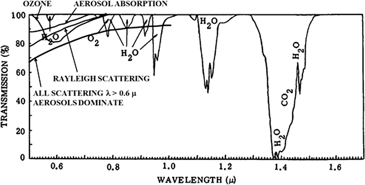 High-power SWL absorption by atmospheric aerosols and molecules can cause a more insidious effect on the beam, e.g., thermal blooming. The absorbed laser energy heats the air, causing both index of refraction and local density changes. The sequel laser beam is then phase aberrated by the heated medium. While slewing and natural winds mollify TB, it can nevertheless have a debilitating effect on SWL far-field performance. Furthermore, the correctibility of this aberration, which is coupled intricately with natural turbulence effects, is today a highly arcane topic! In particular, I know of no experiments that have demonstrated atmospheric compensation for a HP SWL in the presence of both TB and natural turbulence effects! Let’s now turn to sizing the actual potential degradation of TB on our SWL beam. Gebhardt3 has shown that the Strehl loss for TB scales as where is a constant, and where is the absorbed power, is the path length, is the cross wind velocity, is the diameter, and is the wavelength. Assuming that is constant, the above equation has the form where is a constant. Recalling that the general Strehl loss (neglecting jitter) scales asWe then apply or “turn on” TB by multiplying by , or Note this has the precise form of optical jitter, Eq. (4). Thus, TB effects have the same form in our performance equation as does beam jitter! A spectrum of other atmospheric nonlinear effects can be induced by a HP SWL. These include SRS and air breakdown. However, SRS has thresholds above— and air breakdown intensities are several orders of magnitude higher. In general, TB is the dominant atmospheric nonlinear degradation source for SWL GB systems. Atmospheric TB can severely degrade a HP SWL GB system. The effect is caused by laser absorption by aerosols/molecular constituents. Subsequent beam induced heating of the air establishes an aberrated medium for the propagating HP beam. A further wrinkle; TB interacts in a complex fashion with natural optical turbulence. Atmospheric phase compensation in the presence of both effects has not been demonstrated at any level! AOs techniques must be developed and proven effective to enable scaling of SWL GB systems to very high brightness. In examining the wavelength scaling of SWL systems we find that TB can be treated as a beam jitter. 12.SWL Target Effects: the Omega Point!The last—and most important—step on our SWL photon odyssey is the target itself! Figure 15 highlights Felix’s meanderings from device to target. Note that many of his photon friends (Freddies) are lost along the way—because of absorption or scattering. Even the remaining flux has aberrations, only some of which can be “ironed out” (removed) by AO (we will broach AO systems next). The beam arriving on target has suffered both a spread and a Strehl loss. In other words, the flux-in-the-bucket is considerably smaller than expected for a “diffraction-limited” system. Consider a photon impinging on the target. Three events are possible, two of which are undesirable:
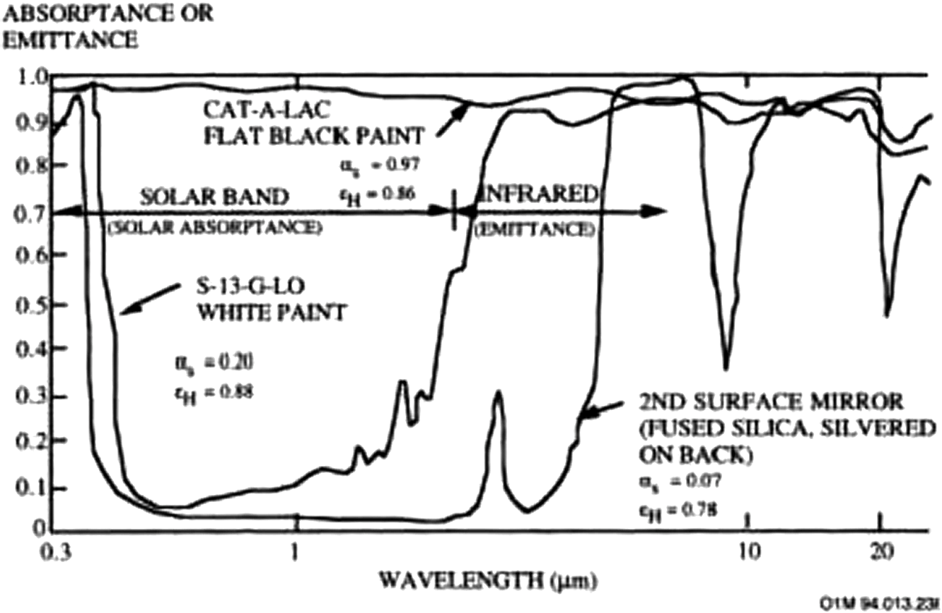
If this absorbed photon flux-in-the-bucket is of sufficient magnitude and duration, then the resulting heating can cause thermal imbalance, melting or burn through of the object …possibly a mission accomplished! Figure 16 presents absorptance wavelength dependence for several surface coating materials. Note that other than black paint, these materials have relatively low absorptance for SWL wavelength in the 1 to 2 μm. At excimer wavelengths (), on the other hand, over 80% of the laser energy is absorbed. We see that to achieve the same lethality, an system may have to deliver approximately four times the flux-in-the-bucket as its shorter wavelength excimer laser cousin. Target coupling is the most important facet of our photon odyssey—as it is the prime mover for SWL system requirements. Only a portion of incident laser energy is absorbed by the target object. This coupling value can vary by almost an order of magnitude over the spectrum of wavelengths and materials. Usually the beam must be held on a target spot for several seconds to effect damage, thus putting stringent requirements on SWL tracking and aimpoint maintenance. 13.Adaptive Optics: a Potential Rx for SWL System BrightnessAO can in principle correct the majority of system and atmospheric-induced phase aberrations, and so recover a near-pristine laser beam. Today’s HP laser systems use mechanical DMs for phase correction. These are complex, cumbersome, and generally unreliable, involving up to hundreds of individually reticulated actuators, plus wavefront sensors and sophisticated software. NLOs could provide automatic, nonmechanical HP beam correction. Though this technology is relative nascent, it is the essential enabling technology for SWL beam control! First, let us discuss mechanical AO. Low order aberrations (e.g., Tilt) are best corrected by a beam steering mirror. This unit, in concert with a Tilt sensor has been shown to correct for two-Axis Tilt at bandwidth . Our system telescope corrects for focus errors. The DM correct HO phase aberrations for both the optical train and the atmosphere. Figure 17 shows a typical mechanical AO subsystem. Note that this system using a return beam from the target vicinity can compensate for most system phase distortions. The mirror itself may be cooled or uncooled. A number of individually reticulated actuators are pushed and pulled to locally deform the thin mirror surface. Typical strokes required for SWL GBL DM actuators are a few wavelengths. Bandwidths of have been demonstrated for 500 actuator DMs. The number of actuators required is determined by the SWL telescope area, , and the system “coherence length”. For a GBL, this latter parameter is generally dominated by the atmosphere, scaling as where is the wavelength, is the target range, and is the atmosphere structure constant (a measure of atmospheric optical turbulence severity). Physically, is the maximum diameter of a transmitting telescope that can deliver, without phase compensation, a high quality beam to a target through the atmospheric path. One finds from Eq. (6) that .Now the number of DM actuators required is , with the area of the telescope. For a 2 m diameter aperture, Table 2 depicts the number of actuators for several laser wavelengths. Table 2Number of actuators for several laser wavelengths.
Note for a fixed aperture, the number of DM actuators scales as ( can be considered a measure of AO system complexity). Remembering that the inherent brightness of a laser scales as , we see that for a fixed aperture size, the ratio of system brightness achievable to complexity of the AO system is wavelength independent (it actually scales as ). A SWL GBL system without a phase compensation system is severely limited in brightness achievable; the maximum aperture for transmission of a high quality beam is , the effective atmospheric coherence length. As noted above, ranges from a few centimeters to for SWLs. An AO system can markedly reduce certain phase aberrations and so increase the “effective ”, defined as . A crucial goal is to render . In fact, if one can sculpt an of several aperture diameters (3 to 4), a corrected atmospheric Strehl of close to unity can be achieved. Remember that two classes of SWL degradations can never be corrected by an AO system:
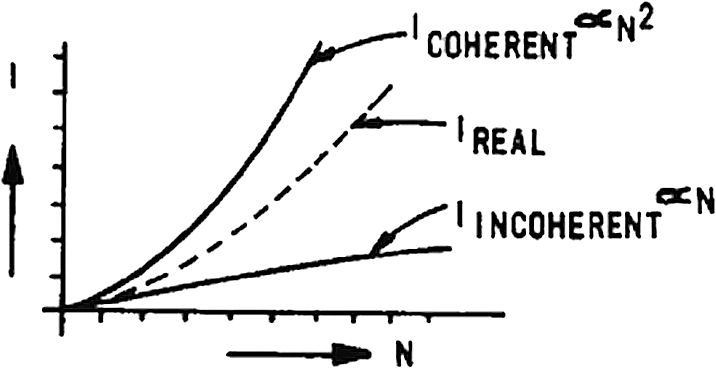
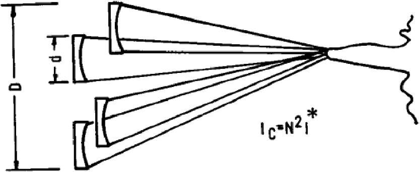
Even discounting such unrecoverable losses, there are clearly no perfect AO systems. In general, there will be residual tilt and HO losses. where is residual RMS tilt variance, is residual RMS phase variance, and is a constant. This has the same form as Eq. (4). Thus, even with a SWL AO system, there is an optimal wavelength for a given ensemble of system phase aberrations. We will return to this crucial point. So …stand by!Mechanical AO systems are cumbersome and complex. In principle AO can correct for many system aberrations, including atmospheric optical turbulence effects. SWL systems having output apertures will require to 2,000 actuators—with system bandwidths . residual phase errors will always exist. An optimal laser wavelength always exists which yields maximum brightness for a particular ensemble of residual errors. 14.Modularity: the High Tech Trek to Ultra Bright SWL SystemsWe noted earlier that as one scales a monolithic laser system in power, device brightness eventually degrades due to loss of BQ. Once the maximum size of this ‘‘unit cell” is known, further scaling can occur via coupling of several unit cells. Let’s estimate the maximum brightness for a monolithic laser to be , with (minimum acceptable device BQ) . Next, consider an array of such coupled lasers; then where is the amplitude of the “th” laser. If all devices are identical and fully coherent, then orNote that the far-field intensity of a perfectly coherent array scales as the square of the number of modules. If this array was totally incoherent, and all lasers pointed to the same spot, it is obvious that Actual device arrays are partially coherent; their performance falls between these extremes as shown in Fig. 18. In general, coupled device arrays are married with coupled telescope ensembles to yield modular SWL systems. Advantages of modular SWL systems include:
For a modular system, with N mirrors, each with diameter , Thus, we find a potential cost savings of for modular optics, compared with a monolithic with the same total optics area! Modular systems have disadvantages:
We continue by examining the far field performance of a coupled array of N SWL systems. Figure 19 shows such an array. We define , as the RMS piston and tilt errors, respectively. The corresponding phase errors are and where is the system wavelength and the diameter of each subaperture. Now the effective diameter of the array isAnd the Strehl loss due to and is just5 Here, we assume no jitter correlations exist among the beam trains. For comparison, the corresponding Strehl loss for a monolithic system is identical with the above, except with . Several important conclusions follow:
Before departing modular systems, let us pursue the above example to show the potential brightness enhancement of an array of coupled devices. Recall for our unit cell, . Suppose the mission requirement is . This can be achieved with
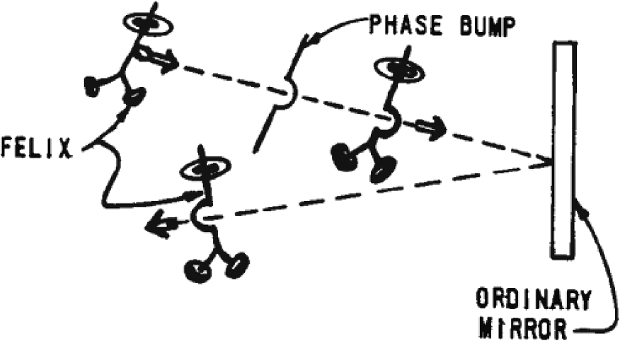
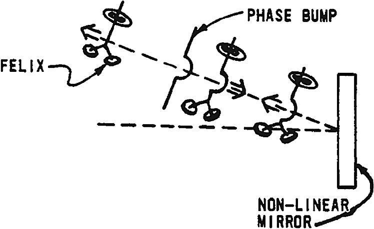
15.Nonlinear Adaptive Optics: the Quintessential Enabling technology for SWL SystemsNLO is the beam control oasis along our path to high brightness SWL systems. Traditional (mechanical) AO systems are cumbersome, costly, complex, and unreliable. While they may suffice for entry level SWL systems, they must “go the way of the albatross” as we “grow the technology”. Conventional AO systems require DMs, wavefront sensors, and reconstructors (analog-to-digital converters). A NLO AO performs all these functions automatically …within the medium. Let’s now “reflect” on a NLO AO system. First, consider an ordinary mirror per Fig. 20. Enroute, Felix the Flux encounters a phase “bump”—any sort of phase aberration. As a result, Felix develops a phase “hump.” After bouncing off the mirror at the specular angle, the hump is still there, but just reversed in phase. Next, consider our NLO mirror in Fig. 21. The NLO materials have two wonderful properties:
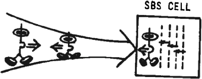
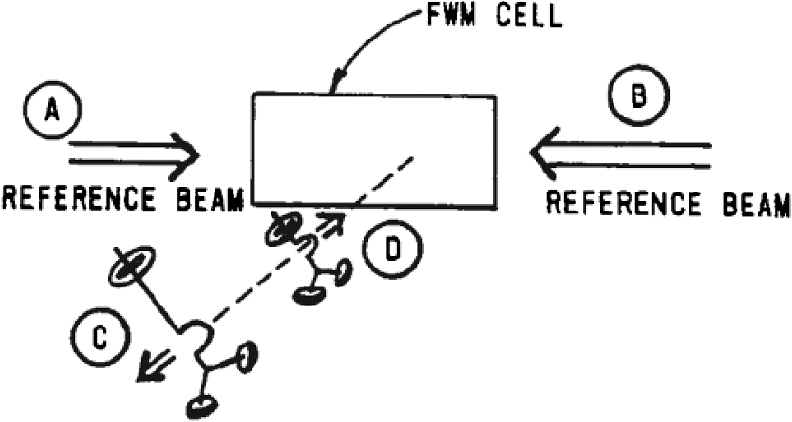
Figure 21 shows Felix getting “straightened” out by the NLO medium. Again, he picks up an unwanted phase “hump” as a result of the bump. Now, however, the NLO medium returns the beam along the same path and with the bump now having the conjugate phase. The happy result when Felix passes back through the aberration is a diffraction-limited Felix. In other words, the NLO process has rendered Felix “Antiaberrated” and he becomes ideal after being transmitted back through the inhomogeneity. I have shown the final Felix a little smaller because the efficiency of NLO processes is less than unity; however, efficiencies of 50% to 80% are not unusual. Albeit with much more difficulty, note that a conventional AO system could have made Felix pristine for completeness. To do so, the hump in Felix would have to be sensed and digitized. Next, several mechanical actuators in the mirror would be pushed against the thin face sheet to create a counterhump. Once finessed, a corrected Felix would reflect at the specular angle. If the mirror could point Felix precisely back through the original atmospheric “bump,” he would emerge nearly diffraction limited. Next, I will sketch the rudiments of NLO processes. Then we will examine some exciting near-term applications. Optically, nonlinear materials can produce a reflected phase-conjugate beam. Figure 22 aids my explanation. Stimulated Brillouin scattering (SBS) occurs when an intense laser beam is directed into a transparent medium. Threshold laser powers are of order 1 MW. A sound wave results which establishes a “density grating,” is with a spacing of . Moreover, this can also be considered an index of refraction “grating,” though the photons are initially reflected weakly; however, this beam interfaces with the continuously arriving incident beam that amplifies the pressure-density variations, which increases the reflected energy etc. The net result can be an efficiently reflected beam that is the phase conjugate of the incident beam. Moreover, each reflected ray precisely retraces its entry path. Four wavelength mixing (FWM) is a NL process in which three beams are input and one is output as shown in Fig. 23. Reference beam A, B, form a density grating. Beam D, the degraded flux, interacts with this pattern. The result again is a back reflected, phase conjugated beam …VOILA! Two features of FWM are particularly attractive for certain applications:
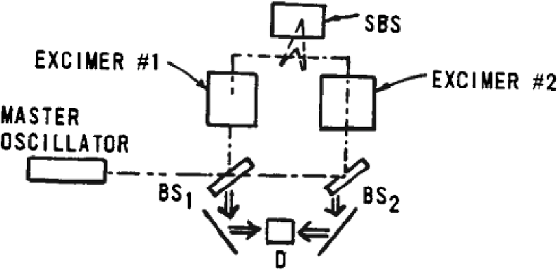
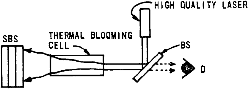
Now I’ll discuss several near term applications for nonlinear AO. Supporting research for some of these applications is now underway within my organization at the AFWL. 15.1.NL AO modular laser systems demonstrationThe premier challenge in coupling together laser systems or “unit cells” is to maintain coherence among the several units.This is an essential prerequisite to realize the brightness enhancement from a fully coherent array. Figure 24 shows our setup at the AFWL involving three 10 to 15 J excimer lasers. One laser is used as a master oscillator (MO) to drive two excimer power amplifiers (PA). First, the high quality MO beam is injected into the two PA. An ideal amplifier would not distort the beam; however, the index-of-refraction variance would have to be controlled to at least for coherence to be maintained between the PAs. These excimer amplifiers have highly aberrated media. Thus, the emerging beams which enter our SBS (gas) cell are both highly aberrated and partially incoherent. The SBS process “retroreflects” and tailors each beam to its phase conjugate. Thus, the amplified beam emerging from the twin excimer amplifiers at detector D are both good quality and highly coherent …and the system brightness is expected to be four times (i.e., factor) that of either beam line. 15.2.Correction for thermal blooming and turbulence via NLO techniquesA high quality, repetitively pulsed laser propagates through a cell containing a highly absorbing gas as seen in Fig. 25. Severe TB results. This aberrated beam is phase conjugated back through the cell and imaged at D. Here are some of our recent observations:
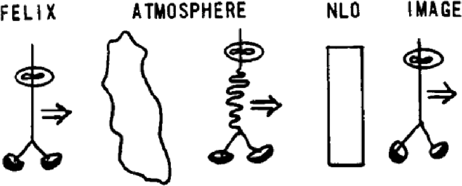
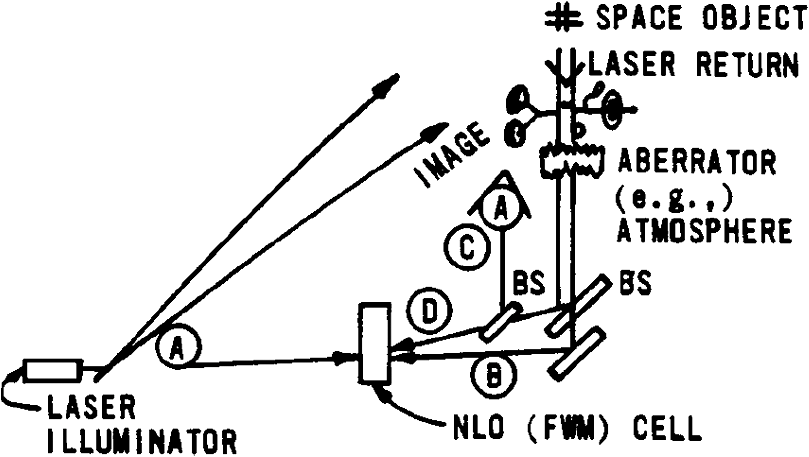
Thus, taking into account slight absorption losses in the TB cell, we conclude that SBS has demonstrated the ability to completely correct for a severe TB environment. This might be extended to the field for propagating a HP short wavelength GBL to space, for example. Figure 26 shows the idea. A low power laser, wavelength , illuminates the object. Some scattered energy is collected, amplified, and SBS processed. Since all distortions from target to SBS cell are imbedded in the entry beam—natural turbulence, TB, amplifier, and optics aberrations, etc., the HP beam arriving at the space target is—diffraction limited. Note that pointing and tracking is “automatic” if within the FOV of our telescopes. Though this concept is “MEGA-Exciting”, it has several limitations. For example, the atmospheric relaxation time is about . That is, if a space object is imaged through the atmosphere from a ground site, a new and random realization of the “distorted” image will be seen each millisecond. Though this restricts viewing frame time to , the illuminator could operate continually for extended high fidelity observations. Secondly, due to light’s finite velocity, distant space objects cannot be “sampled” directly by the low power laser as a prelude to HP SWL satellite engagement. Satellite velocities are ; in the time required for the laser beam to return from the object ( for 300 km range), the satellite has move . Moreover, the HP laser must “lead” by an additional 7 meters. The net result is that the “corrected” HP beam moves through a new and different piece of atmosphere …and so suffers severe distortions. The solution: instead of using the space object as a reference, one must obtain atmospheric optical turbulence information in the lead-ahead direction. Finally, we turn to a FWM application. 15.3.Imaging via nonlinear adaptive optics techniquesApplication of nonlinear techniques offers the prospect of enhanced imaging through distorted media (e.g., atmosphere). Figure 27 shows this scenario. Felix the Flux travel from space through the atmosphere, becomes badly distorted. By using an (FWM) AO, Felix’s image can be recovered after just one way transmission through the atmosphere. Figure 28 shows our lab setup. A laser illuminates the object, while the remainder of the beam serves as reference A. The space image passes through the aberrator (simulated atmosphere) and is split into two parts. One part becomes the other (degraded) reference B. The degraded image D interacts with B in the cell a phase conjugated back reflective C is detected as shown—a nearly pristine image. In summary, system aberrations—optical or atmospheric—can seriously degrade the quality obtained by conventional imaging techniques. One way imaging via nonlinear (FWM) techniques offers significant image enhancement. Resolutions of 20 line pairs/millimeter have been demonstrated at the AFWL …in the presence of strong optical aberrations. Nonlinear AO offers a quantum jump in SWL beam control and image enhancement capabilities. Conventional AO techniques are complex and unreliable, involving costly mechanical DMs, sensor arrays and sophisticated software. A nonlinear AO accomplishes its task automatically and—all the above functions are done within the medium. There is a lofty hurdle to overcome to realize the payoff of NL AO techniques …the dearth of available materials. Nonlinear materials that can handle HP SWL beams and offer fast response times are essential …and not available today! This quest must continue—the payoff of NL adaptive technique for SWL is immense—it is indeed the enabling beam control technology for future high brightness laser systems. 16.Wavelength Scaling: Finding the Optimal SWL for your ApplicationWe have completed our photon odyssey from device to target with our friends Freddy and Felix.We found system aberrations, absorption, and scattering to be rampant. The SWL beam arriving at the target is both spread and reduced in Strehl—that is, the delivered flux-in-the-bucket generally falls well below a diffraction limited system. AO offer an opportunity to correct certain phase aberrations and recover a portion of this “lost” BQ. Mechanical AO systems are cumbersome and costly. Nonlinear AO techniques offer a chance to leap over the beam control chasm in one jump. Although applications abound, the pace of progress will be limited by the availability of materials, particularly for HP SWL missions. Suppose we have carefully optically orchestrated our SWL system—BQ, transfer optics, beam path conditioning, etc.,—and have integrated our best AO subsystem. Our SWL system will still have residual phase errors. Net performance is represented by system Strehl Eq. (7): with where again is the power, the aperture, the device BQ, is the target range, is the wavelength, is the residual jitter (recall, TB can be treated as a jitter), and is the residual phase variance.To examine effects of uncorrected jitter and phase variance on far-field performance, we set in the above equation, finding where is the wavelength yielding maximum system brightness for a given and . Next, we explore several limiting cases of the above optimization relationship.
Results are shown in Table 3: Table 3Optimal wavelength dependence on system jitter to phase ratio (Δ/ϕ).
Again we see jitter has a relatively weak effect on wavelength selection for optimal system brightness. An Example: Suppose our goal is to design and field a SWL system for a ground-to-space mission. We are aware of the brightness optimization equation, but do not understand this magnitude of either natural (e.g., turbulence) or beam-induced (e.g., optics heating, TB) effects. We pick as our candidate laser wavelength. Our instructions to the SWL system designers include
Now our optimal wavelength considering only HO aberrations is where is the RMS (intrinsic) variance in the optical train; is the RMS variance due to natural turbulence; and is the RMS variance from beam-induced mirror heating.Equation (9) reflects the residual errors after our AO system has been activated. Suppose we succeed in building our optics such that (i.e., ) but are surprised to find that the uncorrected contributions from atmospheric turbulence and beam intensity on optics are comparable to ; then Next, we find mechanical jitter has been controlled within tolerance, but TB (uncorrected) is large. Since TB acts as a jitter term, we see from Eq. (7) that our optimal wavelength is still further increased. This table shows that severe blooming could easily raise our “optimal” wavelength above 1.5 μm.The point is that any uncorrected phase aberrations, either tilt or HO, erode the benefits of SWL systems; moreover, these effects tend to push the system toward longer wavelength if maximum brightness (performance) is the goal.
17.ConclusionThe trek to high brightness laser system is very difficult …in fact …with a large exponent. Technical thickets and beam control brambles abound! However, the path to success can be traversed and, the payoff is prodigious. HP lasers are essential elements, though emphasis shifts to beam control—careful optical engineering to orchestrate the laser energy from device to target in a pristine manner. No recipe exists for accomplishing this “PHOTON FEAT”; however, I offer these guideposts along our path to high brightness laser systems:
I close with this précis: the journey to high brightness SWL systems is tortuous …but trekkable …and the payoff is immense! Potential pitfalls and pratfalls exist. Guideposts indicate tough optical engineering, with a dollop of physics, is the key. Ordered priorities in developing these exciting SWL systems are: (No, I did not repeat myself!) HAPPY PHOTON TRAILS! AcknowledgmentsThis note is a product of the author’s circa—20 years of experience in the High Energy Laser (HEL) research and development community. My reflections are steeped in stimulating discussions and tutorials by many friends. My mentors span our Nation’s HEL laser community, and though too numerous to completely list, I salute them all! I have spent most of my career at the Air Force Weapons Laboratory (AFWL), where I have been enveloped by a highly creative and talented cadre of scientists. I offer special accolades to the following men and women from the AFWL: Lt. Col Harro Ackermann, Dr. Pete Avizonis, Dr. Chris Clayton, Dr. Janet Fender, Mr. Bill Finley, Dr. Bob Fugate, Dr. Tom Gavrielides, Dr. Barry Hogge, Dr John Kenemuth, Dr. Paul Kervin, Dr. Mark Kramer, Dr. Vern Schlie, Mr. Larry Sher, Dr. Lyn Skolnik, Mr. Darrell Spreen, Mr. Bill Thompson, Lt. Col Tom Walker, Dr. Larry Weaver, Dr. Ray Wick, Dr. Leroy Wilson, Lt. Col Bill Witt; finally, my photon foxholers. This latter bunch—the enlisted members, junior civilians, and officers—provided insight and unbridled enthusiasm—and a belief in our Nation and its research and development future. Special thanks to Ms. Priscilla Griego, a most gracious lady who labored long hours to transform my meandering musings into coherent prose. Finally, to all of you, enjoy, and keep smiling! ReferencesM. A. Dornheim, Aviation Week and Space Technology, 33 McGraw-Hill, New York
(1986). Google Scholar
Handbook of Military Infrared Technology, Office of Naval Research, Arlington, Virginia
(1965). Google Scholar
F. G. Gebhardt,
“High power laser propagation,”
Appl. Opt., 15
(6), l479
–1493
(1976). http://dx.doi.org/10.1364/AO.15.001479 APOPAI 0003-6935 Google Scholar
D. G. Gilmore, Spacecraft Thermal Control Handbook, Vol. I: Fundamental Technologies, The Aerospace Corporation Press, California
(2002). Google Scholar
C. B. Hoggeet al.,
“Physical optics of multiple aperture systems,”
Appl. Opt., 27
(24), 5127
–5134
(1988). http://dx.doi.org/10.1364/AO.27.005127 APOPAI 0003-6935 Google Scholar
BiographyKeith G Gilbert received his BS/MS in physics from the University of New Mexico in 1961, and a PhD in applied physics from the University of California in 1968. He retired from a 26-year Air Force career as a Colonel in 1988, stepping down from his position as director of the Advanced Radiation Technology Office of the Air Force Weapons Laboratory. His director position capped a career as a “Blue-Suit Scientist”; as a director, he led all of the laser-related programs in the Laboratory. He continued to remain active in research and development after leaving the Air Force; his current passions are in alternative energies and sustainability. |