
|
|
1.IntroductionThe use of laser trapping devices, commonly known as optical tweezers, was first demonstrated by Ashkin in 1970.1 In the past two decades, the laser trapping technique has been further extended to realize multibeam optical tweezers and has been widely used for noncontact micro/nano-manipulation in various scientific fields, particularly in biomedical fields, for applications such as in Lab-on-a-Chip, bio-MEMS/NEMS, and microfluidic systems. The multibeam techniques used in optical tweezers such as holography,2 time-shared scanning,3 and generalized phase contrast (GPC),4 allow us to trap and manipulate many micro-objects simultaneously, in contrast to mechanical microhands5 which manipulate only one object at a time. As reported in our previous paper,6 we have developed a hybrid optical tweezers system, for dynamic handling of massive microbead arrays, consisting of two multibeam techniques including the GPC method using a spatial light modulator (SLM) and the time-shared scanning method using the galvano mirrors (GMs). This system was able to provide us with greater versatility, while the GPC method created the trap fields for immobilizing massive arrays, where the beads were manipulated smoothly and quickly by the GM scanning method. However, in the previous system, arrays formed by the GM scanning tweezers, based on the time-shared synchronized scanning (T3S) technique, could be handled only in a two and half dimensional (2.5D) working space. The manipulation in a 2.5D working space means that the controlled movement of objects in three-dimensional (3D) Cartesian coordinates is limited to 3D translations and two-dimensional (2D) rotations in -planes. This limitation arose from the lower bandwidth (several hertz in the previous system) of the -axis manipulation because the manipulation was based on lens translation with a PC-controlled linear stage. The lens translation had high inertia and required millimeter order motion for the -axis manipulation. Therefore, for the true 3D manipulation of micro-objects, an alternative -axis manipulation method with higher bandwidth is required. In this paper, we present an improved hybrid optical tweezers system that can be used for the controlled 3D manipulation of multiple micro-objects with the help of an electrically focus-tunable lens with higher bandwidth. 2.Design Concept and Developed SystemThe 3D micro/nano-manipulation using optical tweezers is a significant technique for various scientific fields ranging from biology to nanotechnology. However, the use of optical tweezers alone is not sufficient to dexterously manipulate a nonspherical object in a true 3D working space or to automatically trap and transport objects for the following two reasons. First, to prevent biological objects from thermal damage, we generally use laser beams in the infrared (IR) region, therefore, we cannot exactly identify the actual focal positions of incident beams. Second, nonartificial objects generally have an inhomogeneous refractive index and a nonspherical shape, consequently, undesired torques, as well as forces, may be generated in the trapped objects. Hence, to achieve dexterous or automatic manipulation for various micro-objects, we have proposed the concept of a multibeam micromanipulation system which combines image processing and automatic control techniques.7 Based on the above conceptual system design, we developed a hybrid optical tweezers system whose optical structure could be easily linked to an inverted microscope via its epi-fluorescence port. Figure 1 shows the optical and control system configurations of the developed system. The hybrid optical tweezers system uses two multibeam optical tweezers techniques which are the GPC method using an SLM and the T3S method using two commercially available fast-beam-steering devices. The single laser source is a continuous wave (cw) Nd:YAG laser (Laser Quantum, FORTE, 1064 nm, 700 mW, , England, United Kingdom); the beam emanating from the laser source passes through a half-wave plate () and is split into two beams (- and - polarized beams) by a polarized beam splitter (PBS). One set of optical tweezers, based on the GPC method, is composed of an SLM, a phase contrast filter (PCF), and lenses ( and ) and it uses the -polarized beam. The -polarized beam is used to make the other set of optical tweezers which is based on the T3S method and is composed of an electrically focus-tunable lens (Optotune, EL-10-30-NIR-LD, , response , Switzerland), a two-axis gimbal-mirror (Newport, FSM-300, California, USA), and two relay lenses ( and ). The closed-loop amplitude bandwidth of the gimbal-mirror is 800 Hz and the resolution is 1 μrad [ for of digital-analog (DA) voltages]. The laser power can be distributed between the two methods in varying proportions with the half-wave plate. The optical potential energy landscapes8 created by these tweezers can be controlled independently since the - and -polarized beams do not interfere with each other. Fig. 1Optical and control system configurations of the hybrid optical tweezers for true 3D micromanipulation. The GPC part (orange beam: left) is controlled by the bitmap images, and the T3S part (red beam: right) is controlled by the DA voltages. 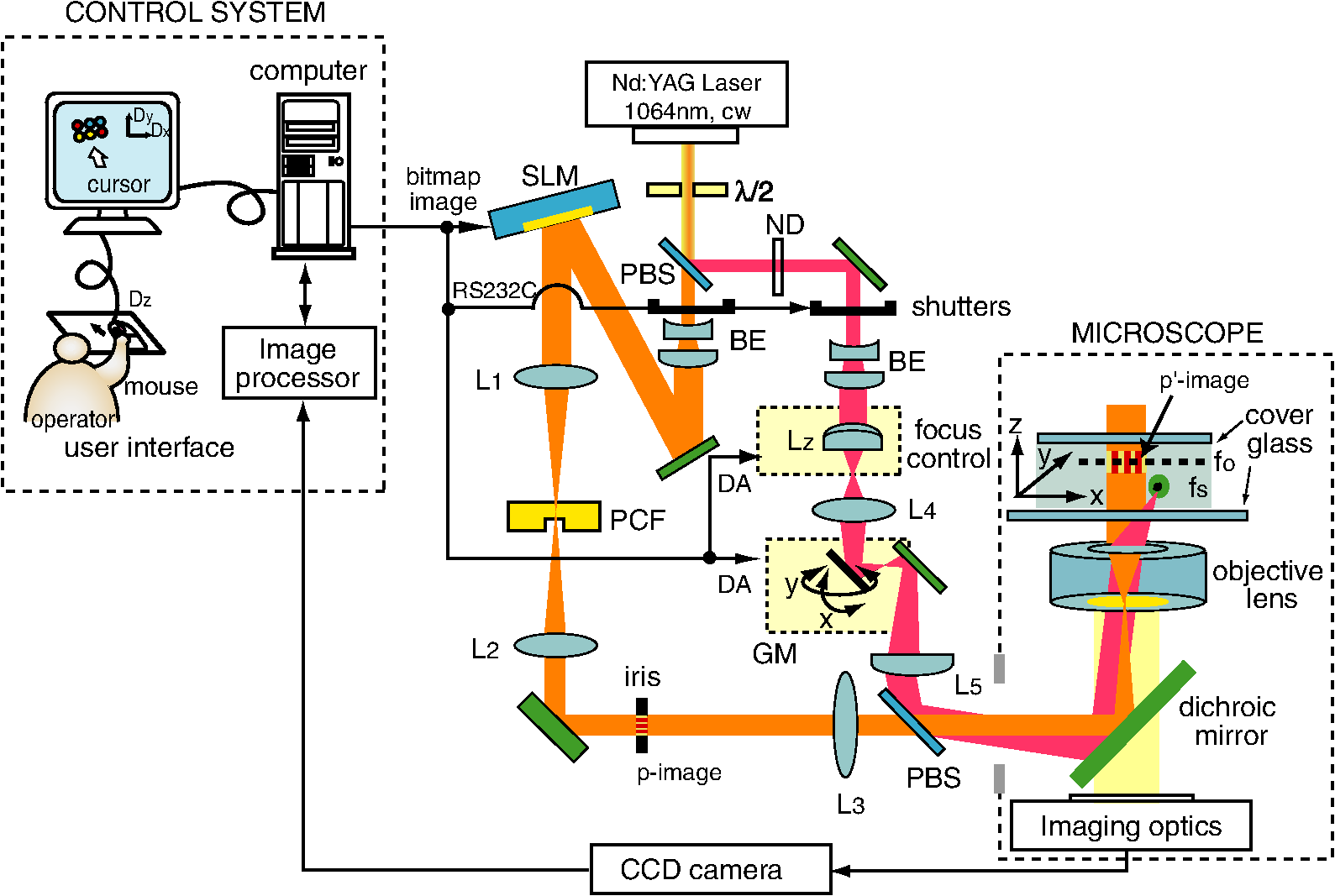 In this new hybrid system, the GPC part is the same as that in our previous hybrid system,6 the T3S part is redesigned for true 3D-T3S manipulation based on the design guidelines for stable 3D scanning traps, reported in our previous paper,9 while retaining the design concept and system features of the previous hybrid system. Consequently, the T3S part enables us to independently and simultaneously control several trap positions in a true 3D working space while the GPC part provides massive 2D traps (that is, over several tens of traps). The designed steering ranges are and for the objective (Olympus, UPlanFLN , , Japan), , and . The number of the beads that can be handled by the T3S part is limited to for a 2D/3D manipulation owing to the dwell time of scanning (typically, 10 or 15 ms for 2 μm beads), which depends on the bead size and the response time of both the gimbal-mirror and the focus tunable lens. The advantage of our system is the direct control of 2D/3D trap positions using both the bitmap images and the DA voltages which have a one-to-one correspondence with the 2D/3D trap positions. Therefore, compared to other systems based on the holographic method, we can manipulate multiple objects, in a true 3D working space, smoothly and precisely without the presence of ghost traps10 in the holographic tweezers. 3.Demonstrations of 3D Manipulation3.1.Controlled Manipulation along 3D PathsHere, using the T3S part alone, we demonstrate that the controlled manipulation of five beads along 3D paths, defined by explicit functions of time , can be simply achieved in real time without prior computation of their manipulation paths. Figure 2 (Video 1) shows snapshots captured with a CCD camera and presents the results of the controlled manipulation of five beads (Duke Scientific, borosilicate microsphere, , California, USA). The laser power at the entrance pupil of the objective lens was 155 mW and the scanning dwell time for each bead was 15 ms. Based on the time-shared scanning approach, the -, -, and -coordinates of each bead, at time , were controlled according to the functions where the subscript and superscript of the coordinates indicate that the values of the coordinates are for the ’th bead and for the interactive rotation angle , respectively, and whereFig. 2(Video 1) Interactive rotation control about the -axis and simultaneous rotation of five beads that form a pentagon about its center (Video 1, QuickTime, 1.2 MB) [URL: http://dx.doi.org/10.1117/1.OE.52.4.043002.1]. 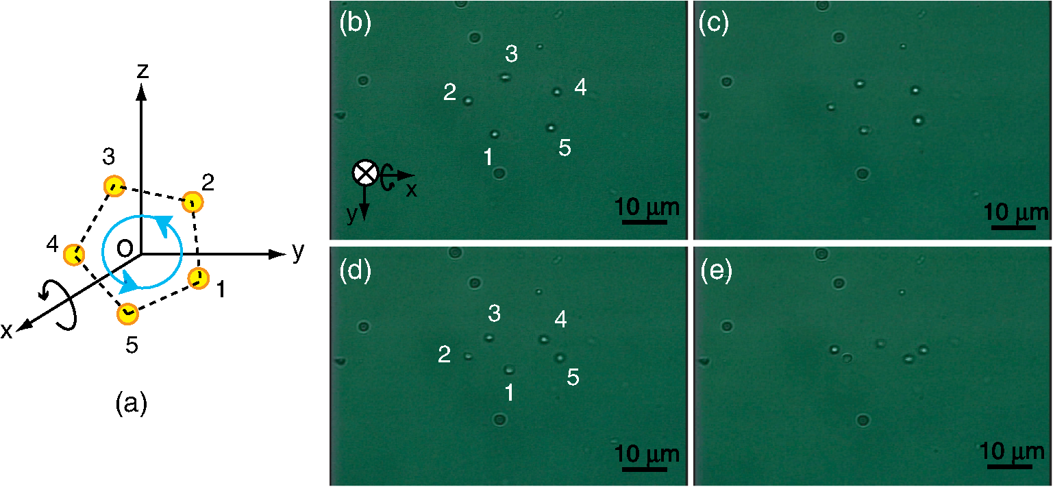 Consequently, the five trapped beads, which formed the shape of a pentagon owing to the 3D time-shared scanning, were interactively rotated by an angle of about the -axis in Cartesian coordinates while the pentagon was rotated about its center. 3.2.Controlled Rotation of Four Beads about Arbitrary Axes in 3D SpaceHere, using the T3S part alone, we also demonstrate that the controlled rotation of four beads, which hypothetically form a single rigid body (that is, a tetrahedron), about an arbitrary axis in Cartesian coordinates, can be simply performed using “homogeneous transformation” in computer graphics,11 in real time. Figure 3 (Video 2) shows snapshots captured with a CCD camera and presents the results of the interactive and controlled 3D rotation of four unconnected beads that form a tetrahedron. The homogeneous representation of the tetrahedron in Fig. 3(a) is where the ’th column of matrix denotes the position of the tetrahedron’s corner indicated by the number in Fig. 3(a). Note that each of the matrix’s elements is not the actual position along the respective axis, but rather the normalized distance from the origin. The four beads were trapped at the tetrahedron’s corresponding corners and it was possible to rotate them about each axis of the 3D Cartesian coordinate system. The laser power, the scanning dwell time, and the sample all remain the same as in the demonstration described in earlier text. First, the four beads, the positions of which are indicated in Fig. 3(a) by the numbers corresponding to the tetrahedron’s corners, were trapped at their initial positions [Fig. 3(b)] and rotated about the -axis [Fig. 3(c)] using the rotation matrix and the translation matrix , which are given by where is the interactive rotation angle about the -axis. Next, the four beads were also rotated about the -axis [Fig. 3(d)] and the -axis [Fig. 3(e)] from their initial positions using the rotation matrices where and are the interactive rotation angles about the -axis and -axis, respectively.Fig. 3(Video 2) Interactive and controlled 3D rotation of four beads that form a tetrahedron about the arbitrary axes of a 3D Cartesian coordinate system (Video 2, QuickTime, 2.3 MB) [URL: http://dx.doi.org/10.1117/1.OE.52.4.043002.2].  3.3.Automated Assembly and Interactive 3D Manipulation of ArraysBy using both the GPC tweezers and the T3S tweezers, we have demonstrated the automated assembly of microbead arrays and the subsequent 3D manipulation of the arrays. Figure 4 (Video 3) shows a sequence of images recorded with a CCD camera and shows the results of the fully automated assembly and immobilization of two squares made from microbeads using only the GPC part and the subsequent translation of a single array (that is, the inner array) in a 3D working space using the T3S technique. The laser power for the GPC tweezers was 156 mW and that for the T3S tweezers was 50 mW. The sample is polystyrene microbeads (Polysciences, 2 μm, Pennsylvania, USA). First, in order to fully and automatically assemble the arrays of microbeads (that is, the two square arrangements of microbeads), the center positions of all beads in an image were detected by the Hough transform12 and the subsequent irradiation of disk-shaped beams based on the GPC method trapped the 28 beads at their initial detected positions, where all beads were trapped against the lower surface of an upper cover glass in the same -plane, namely, the microscope’s imaging plane [Fig. 4(a)]. Second, under a modified version of the control algorithm described in our previous paper,13 the 28 trapped beads were transported using only the GPC tweezers to form two squares [Fig. 4(b)–4(d)]. Third, four beads forming the inner array were firmly and simultaneously trapped by the T3S tweezers instead of the GPC tweezers, while the 24 beads forming the outer square remained trapped by the GPC tweezers. Finally, subsequent 3D translations of the array, namely, lowering of the smaller square [Fig. 4(e)], lateral translation of that square to outside the large square [Fig. 4(f) and 4(g)], and raising of the smaller square back to the original level [Fig. 4(h)], could successfully transport the square in 3D space. Consequently, the array, which was initially inside the large square, was able to reach the outside of the large square while maintaining its geometrical shape. Figure 4(i) illustrates these 3D translations of the array in a cross-sectional view where yellow circles indicate the array and red circles indicate the large square formed by the 24 beads. Fig. 4(Video 3) Fully automated assembly of two squares and subsequent 3D translation of the inner array (Video 3, QuickTime, 5.1 MB) [URL: http://dx.doi.org/10.1117/1.OE.52.4.043002.3].  3.4.DiscussionsIn the two demonstrations using the T3S part alone, the initial loadings of beads to the 3D arrays (that is, a pentagon and a tetrahedron) were autonomously completed by moving the microscope’s XY-table. Because their 3D geometry is simple and the strongly focused, scanning traps based on geometrical optics can be exactly generated in 3D Cartesian coordinates without ghost traps that exist in the holographic methods. In order to assemble complex 3D geometries, in the future work, the initial loading process will be automated by developing both collision-free control algorithms13 for 3D arrays and 3D position monitoring techniques.14,15 On the other hand, in the third demonstration using both the GPC tweezers and the T3S tweezers, the initial loading of beads was fully automated using the Hough transform because all detected beads at their initial positions were able to suspend in the single -plane (that is, 2D working space) by the GPC beams. The subsequent process of our third demonstration was performed, in the strict sense of the word, in a 2.5D working space. However, in the future work, the application of the morphing process16 from a 2D array to a 3D array will be able to fully automatically assemble 3D structures only using a collision-free control algorithm. In the morphing process using the 3D-T3S tweezers, no 3D position monitoring of trapped beads may be required after amplitude calibration because such morphing of 3D traps can be exactly controlled by DA voltages that have a one-to-one correspondence with the 3D trap positions. 4.ConclusionFor automated true 3D manipulation of multiple micro-objects, we developed an improved hybrid optical tweezers system consisting of GPC tweezers with an SLM and 3D-T3S tweezers with a two-axis fast-steering mirror and an electrically focus-tunable lens and we demonstrated three examples of controlled 3D manipulation. Although the demonstrations performed are simple, the developed system can be used as a valuable noncontact manipulation tool in various scientific fields ranging from biology to nanotechnology. Additionally, the presented hybrid system offers an alternative platform for the optical assembly17 and probing18 of 3D microstructures because our system, which can be easily linked to a standard microscope, can in a simple, precise, and independent manner, control 3D multiple traps under visual control schemes by machine vision using the bitmap images/DA voltages that have a one-to-one correspondence with the 2D/3D trap positions. ReferencesA. Ashkin,
“Acceleration and trapping of particles by radiation pressure,”
Phys. Rev. Lett., 24
(4), 156
–159
(1970). http://dx.doi.org/10.1103/PhysRevLett.24.156 PRLTAO 0031-9007 Google Scholar
D. G. Grier,
“A revolution in optical manipulation,”
Nature, 424
(6950), 810
–816
(2003). http://dx.doi.org/10.1038/nature01935 NATUAS 0028-0836 Google Scholar
C. Mioet al.,
“Design of a scanning laser optical trap for multiparticle manipulation,”
Rev. Sci. Instrum., 71
(5), 2196
–2200
(2000). http://dx.doi.org/10.1063/1.1150605 RSINAK 0034-6748 Google Scholar
J. GlückstadD. Palima, Generalized Phase Contrast, Springer, Dordrecht, Netherlands
(2009). Google Scholar
T. TanikawaT. Arai,
“Development of a micro-manipulation system having a two-fingered micro-hand,”
IEEE Trans. Robotic. Autom., 15
(1), 152
–162
(1998). http://dx.doi.org/10.1109/70.744610 IRAUEZ 1042-296X Google Scholar
Y. Tanakaet al.,
“Hybrid optical tweezers for dynamic micro-bead arrays,”
Opt. Express, 19
(16), 15445
–15451
(2011). http://dx.doi.org/10.1364/OE.19.015445 OPEXFF 1094-4087 Google Scholar
Y. Tanakaet al.,
“Development of PC-controlled laser manipulation system with image processing functions,”
Proc. SPIE, 6374 63740P
(2006). http://dx.doi.org/10.1117/12.684978 PSISDG 0277-786X Google Scholar
M. P. N. Juniperet al.,
“Acousto-optically generated potential energy landscapes: potential mapping using colloids under flow,”
Opt. Express, 20
(27), 28707
–28716
(2012). http://dx.doi.org/10.1364/OE.20.028707 OPEXFF 1094-4087 Google Scholar
Y. Tanaka,
“3D multiple optical tweezers based on time-shared scanning with a fast focus tunable lens,”
J. Opt., 15
(2), 025708
(2013). http://dx.doi.org/10.1088/2040-8978/15/2/025708 JOOPDB 0150-536X Google Scholar
C. Hesselinget al.,
“Controlling ghost traps in holographic optical tweezers,”
Opt. Lett., 36
(18), 3657
–3659
(2011). http://dx.doi.org/10.1364/OL.36.003657 OPLEDP 0146-9592 Google Scholar
Principles of Interactive Computer Graphics, 333
–354 2nd ed.McGraw-Hill, New York
(1979). Google Scholar
D. H. BallardC. M. Brown, Computer Vision, 119
–148 Prentice-Hall, New Jersey
(1982). Google Scholar
Y. Tanakaet al.,
“Dynamic micro-bead arrays using optical tweezers combined with intelligent control techniques,”
Opt. Express, 17
(26), 24102
–24111
(2009). http://dx.doi.org/10.1364/OE.17.024102 OPEXFF 1094-4087 Google Scholar
D. RuhB. TränkleA. Rohrbach,
“Fast parallel interferometric 3D tracking of numerous optical trapped particles and their hydrodynamic interaction,”
Opt. Express, 19
(22), 21627
–21642
(2011). http://dx.doi.org/10.1364/OE.19.021627 OPEXFF 1094-4087 Google Scholar
J. S. Damet al.,
“Three-dimensional imaging in three-dimensional optical multi-beam micromanipulation,”
Opt. Express, 16
(10), 7244
–7250
(2008). http://dx.doi.org/10.1364/OE.16.007244 OPEXFF 1094-4087 Google Scholar
G. Sinclairet al.,
“Assembly of 3-dimensional structures using programmable holographic optical tweezers,”
Opt. Express, 12
(22), 5478
–5480
(2004). http://dx.doi.org/10.1364/OPEX.12.005475 OPEXFF 1094-4087 Google Scholar
P. J. Rodrigoet al.,
“Optical microassembly platform for constructing reconfigurable microenvironments for biomedical studies,”
Opt. Express, 17
(8), 6578
–6583
(2009). http://dx.doi.org/10.1364/OE.17.006578 OPEXFF 1094-4087 Google Scholar
D. B. Phillipset al.,
“An optically actuated surface scanning probe,”
Opt. Express, 20
(28), 29679
–29693
(2012). http://dx.doi.org/10.1364/OE.20.029679 OPEXFF 1094-4087 Google Scholar
Biography Yoshio Tanaka is a senior research scientist of National Institute of Advanced Industrial Science and Technology (AIST), AIST Shikoku in Japan. He received the BE, ME, and PhD degrees in electronic engineering from the University of Tokushima in 1982, 1984, and 1997, respectively. In 1986, he joined Government Industrial Research Institute, Shikoku, MITI of Japan, the predecessor of the present AIST Shikoku, where he was engaged in research on robotics and mechatronics. Now, his research interests include opto-mechatronics, bio-MEMS/NEMS, and micromanipulation using laser trapping for various scientific fields.  Shogo Tsutsui received the BE and ME degrees in reliability-based information systems engineering from Kagawa University in 2009 and 2011, respectively. He has been working on development of a hybrid optical tweezers system combined with intelligent control techniques.  Hiroyuki Kitajima is an associate professor of Graduate School of Engineering, Kagawa University in Japan. He received the BE, ME, and PhD degrees in electrical and electronic engineering from the University of Tokushima in 1993, 1995, and 1998, respectively. In 1999, he joined Kagawa University. Now, his research interests include bifurcations and synchronizations in nonlinear dynamical systems. |


