|
|
1.IntroductionWe have built a 1.5-m class visible light space telescope with a wide field-of-view (FOV) on a Discovery Mission budget. In NASA’s Astrophysics Division this is comparable to a medium-class strategic mission, also referred to as a Probe. Members of the science team worked closely with the engineers at Ball Aerospace on key requirements, design, implementation, test, and data interpretation decisions. Sophisticated design, analysis, and modeling tools at both Brashear and Ball Aerospace, modern materials and manufacturing processes, and state-of-the art optical test facilities and practices allowed thorough system-level verification that produced a very capable instrument. The Kepler mission is providing the exoplanet science community with a rich harvest of new data regarding the frequency and architectures of planetary systems around other stars.1,2 Stellar astrophysics is also benefiting from the temporal extent, time resolution, photometric precision, and sheer number and variety of stars being observed.3–5 2.Meeting the Science RequirementsThe Kepler telescope was designed and built to meet the ambitious scientific requirements of NASA’s first dedicated exoplanet mission.6 Working in conjunction with the 96 Mpx focal plane as a photometer, it provides the exquisite sensitivity required to detect the miniscule photometric signals of transits of earth-size planets orbiting sun-like stars. The primary scientific goal is to derive an estimate of the fraction of sun-like stars that host planetary systems, especially those that include earth-like planets in the Habitable Zones where liquid water could exist on the surface.7 This fraction is often called “Eta-Earth”, . The probability that the alignment of the orbital planes allows transits to be visible to Kepler is on the order of 0.5%, so a large number of stars must be monitored to ensure a statistically significant number of detections, and a meaningful null result if fewer are observed. A minimum of 25 positive detections was thought to be acceptable.2 This implies watching at least 5000 primary targets if , and many more stars if is much smaller. It was also required that the signal-to-noise (S/N) ratio of the detection of a single transit event be 4 or greater, improving to after three or more detections. This would eliminate most false-positive events, and would be possible for stars of magnitude 12 and brighter. The sample of “sun-like” stars would include single Main Sequence stars with spectral types F, G, and K, and “earth-like” planets being those with diameters between 0.8 and 2 times that of our Earth. Given the distributions of stellar properties in the galaxy, especially magnitudes, a working sample many times the minimum was needed. Additional stars were included to sample hotter and cooler spectral types, eclipsing binaries, giants, and targets observed primarily for astrophysical interest. The Kepler team settled on 150,000 stars brighter than magnitude 16 as being an appropriate number.8 Since we do not know a priori which stars will show transits, when they will occur, or how long they will last, it is necessary to monitor all of the stars simultaneously, with a short time resolution, with few interruptions, and for a time long enough to detect at least three transits of a given planet. (Three transits provide two measurements of the orbital period, and three observations of their depth and duration, which increases confidence in the reality of the events as signatures of a planet.) The target field therefore needed to be at a high enough ecliptic latitude to always be outside of a sun-avoidance zone and to avert problems with asteroids or other solar system objects, and to be close enough to the galactic plane to have a high density of stars, but far enough above or below to minimize overcrowding and confusion. Finally, the field needed to be accessible to the northern-hemisphere ground-based observatories (Keck, Lick, McDonald, Palomar, Las Cumbres, and Mt. Hopkins) that conduct follow-up observations of Kepler’s discoveries. In the densely populated star field in Cygnus, an area was identified that contains a large number of suitable stars,9,10 from which the Kepler Input Catalog was compiled.11,12 The field is centered on 22 min 40 s, , galactic coordinates , , ecliptic longitude, . The telescope was designed to have a 16-deg diameter FOV, of which 115 sq deg are actively used to monitor this field. The magnitude of the photometric signal is the fraction of the stellar disk that is blocked by the disk of the planet. An Earth–Sun analog will produce a transit depth of about 80 parts per million (ppm), lasting for at most a few tens of hours, and repeating once per “year.” The system was required to provide photometric data with a precision of 20 ppm in 6.5 h for 12th magnitude stars, resulting in a S/N ratio of 4 for such an event. This system-level noise metric is quantified by the Kepler team as the “combined differential photometric precision” (CDPP).2 During the many years of study and development many effects were identified that could contribute to the noise. These were grouped into three categories: photon Poisson noise, instrumental and measurement noise, and stellar variability, from which the CDPP is derived as the root-sum-square. As a systems engineering rule of thumb one tries to allocate the errors about equally, so individual noise levels on the order 12 ppm were indicated. Happily this is about what is observed for solar variability on a transit timescale, although the in-orbit observations show that many stars exhibit larger ranges.13,14 The engineering challenge was then to build a system that collected a large enough photon signal while introducing small enough instrumental noise to meet its share of the error budget. The focal plane array was built as a mosaic of 42 charge-coupled devices (CCD), using best engineering practices to package the detectors and their local electronics to minimize noise.15 Integration times were planned to expose to close to full well ( electrons), making read noise insignificant, while being short enough to prevent cosmic ray events from accumulating. Operating at minimizes dark current. Figure 1 shows the system configuration that achieves the required performance. Fig. 1The Kepler photometer contains a Schmidt telescope with a spherical primary mirror, a refractive corrector, and the focal plane array assembly located between the two at the convex focal surface. The system size was determined by the scientific requirements for photon collection, and limited by the capacity of the Delta II launch vehicle and the mission budget. 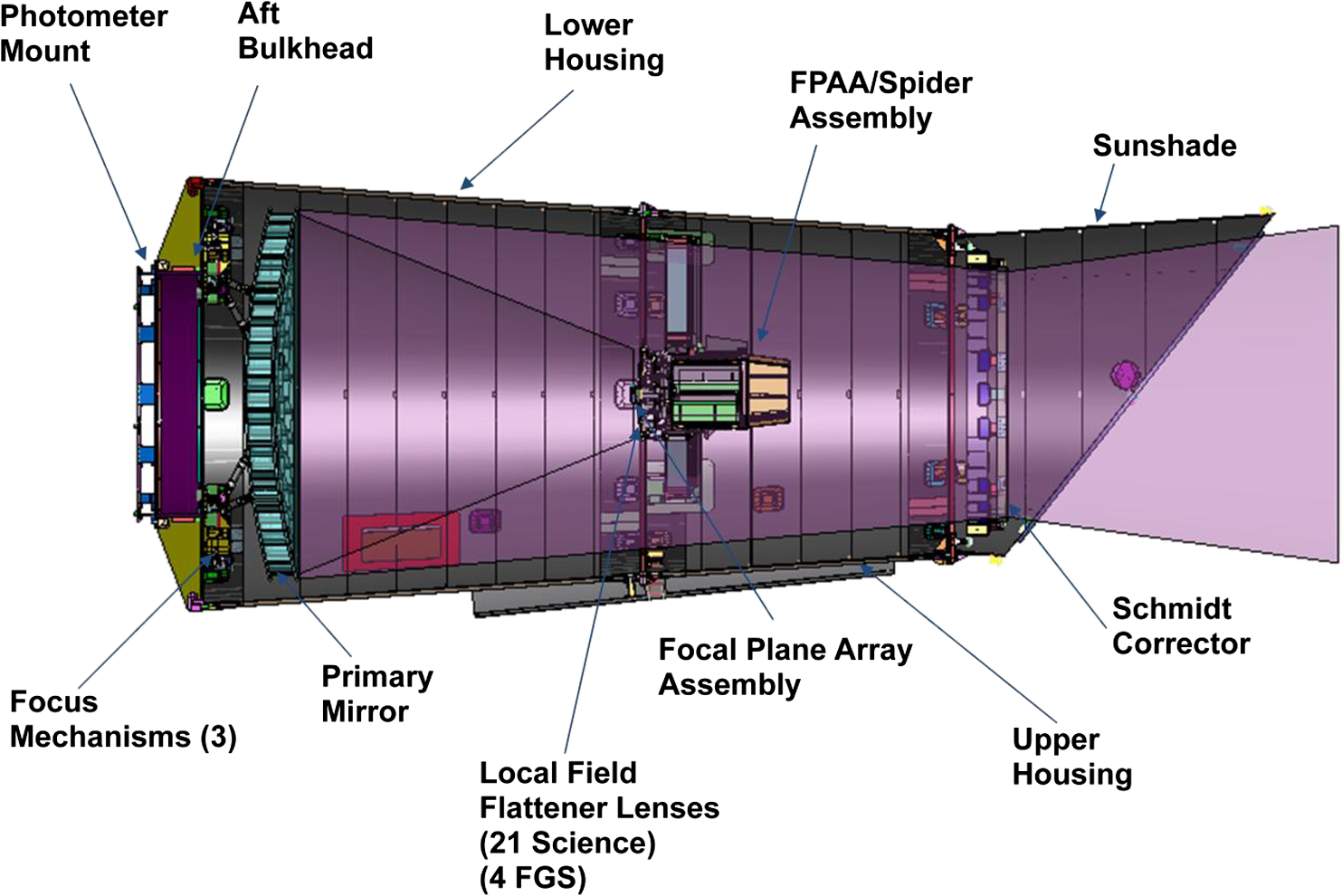 3.Design and Fabrication of the TelescopeThe telescope consists of a 1.4-m spherical primary mirror and a plano-convex refractive corrector. The primary mirror assembly and support structure was designed, fabricated, and tested by L-3 Integrated Optical Systems (formerly Brashear) under contract to Ball Aerospace. Corning ULE® was selected as the material owing to its very low coefficient of thermal expansion (CTE), mature construction techniques, and ability to be lightweighted. The mirror has a 9.75-mm thick front facesheet, an 8-mm thick back facesheet, and a waterjet cut core 275 mm thick with 1.3-mm walls. L-3 Integrated Optical Systems achieved 88% light-weighting, for a mass of 86.3 kg and an areal density of . As a risk reduction, a duplicate set of bond pad locations was designed into the backside, which added extra mass and complicated achieving the desired stiffness. This design feature was selected to ensure that there were positions for mounting the bipods and still achieving flight should the epoxy bond joints not achieve 100% success. There were no issues during manufacturing or subsequent integration into the full telescope. Six invar pads were bonded to the backsheet using an epoxy adhesive to provide the structural interface. Carbon fiber struts with titanium flexures and fittings completed the mechanical system. Three actuators in the mounts allow focus adjustment in piston, tip, and tilt, the only active alignment authority during flight. The primary mirror assembly was fabricated at room temperature, 23°C (296 K), but operates near (250 K) in space. The 2.785-m radius of curvature results in a fast, element. Sophisticated finite element analysis models were developed by L-3 Integrated Optical Systems16 to guide the design and in-process metrology to ensure that the cold and gravity-free surface figure would meet the surface specification. Particular attention was paid to deformations introduced at the six bonding pads by small but nonzero differences in CTE between the mirror, the adhesive, and the struts. This integrated modeling and manufacturing enabled a time and cost-efficient system development. Figure 2 shows the primary mirror upon delivery to Ball Aerospace. Figure 3 shows it after coating. Fig. 2Kepler’s 1.4-m-diameter, primary mirror is made of Corning ULE®. It was fabricated and polished by L-3 Integrated Optical Systems (formerly Brashear). The water-jet cut core achieved 88% light-weighting, for an areal density of , and a mass of 86.3 kg. 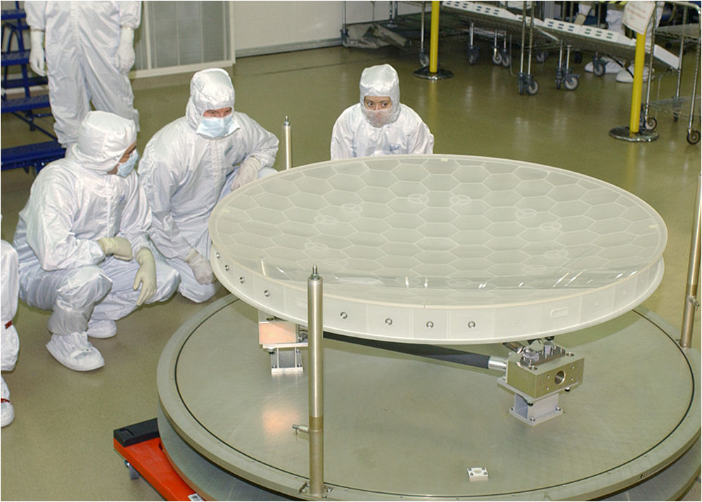 Fig. 3The protected silver coating provides maximum reflectivity over the Kepler photometric bandpass. 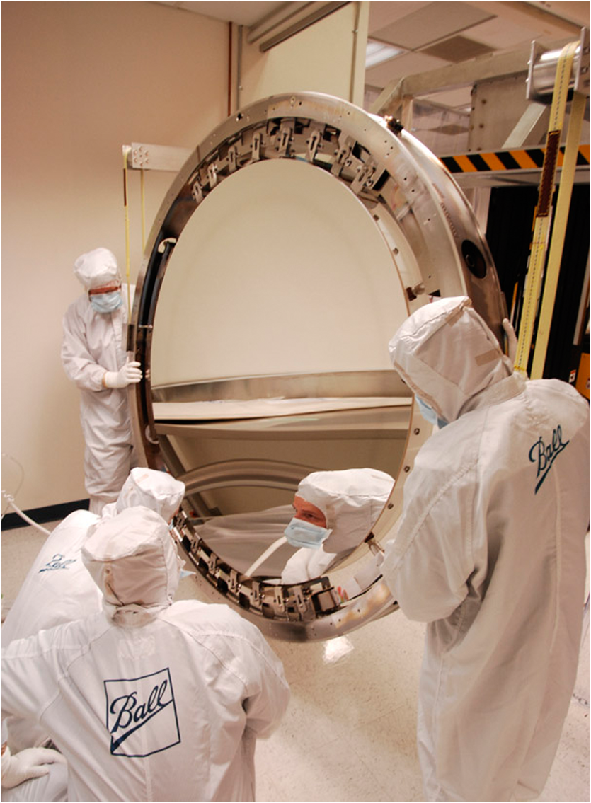 The single element, plano-convex Schmidt corrector was also developed by L-3 Integrated Optical Systems, and finished by their Tinsley facility. Corning fused silica was selected by virtue of its radiation resistance, low CTE, and ease of manufacturing in the required size. The clear aperture of 0.95 m is defined by a composite stop mounted above the outward facing flat surface. Invar pads are bonded and bolted to flexures which attach to a structural ring assembly. Figure 4 shows the corrector being inspected in preparation for bonding to its support flexures. Fig. 4The Corning fused silica, plano-convex Schmidt corrector was fabricated by L-3 Integrated Optical Systems (formerly Brashear and Tinsley). Here it is being prepared for bonding of its support flexures at Ball Aerospace. 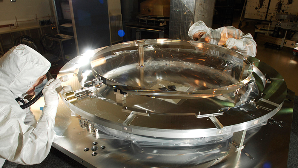 One broad photometric bandpass between (5% transmission points) is used to maximize the number of photons delivered to the focal plane while excluding the variable chromospheric Ca II H and K line region. This “Kepler passband” () is slightly wider than the combined astronomical V and R bands, and is normalized to be numerically very close to R band magnitudes.2,17 It is achieved by the coating on the primary, the transmission of the corrector, the transmission of sapphire field-flattening lenses mounted on the focal plane, and the response of the detectors. The silver coating on the primary enhances the reflectivity at the longer wavelength end where the detectors are most sensitive. It exceeds 96% between 500 and 900 nm. The transmission of the antireflection (AR)-coated corrector averages 98% between 500 and 900 nm. Figure 5 shows the corrector with its AR coating applied. The field lenses exceed 92% transmission over 445 to 865 nm. Fig. 5A broadband anti-reflective coating was applied to the corrector to maximize throughput and reduce stray light artifacts. 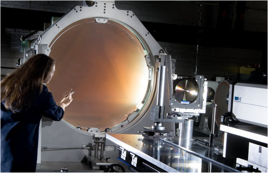 The convex focal surface has an image scale of , and it therefore requires 300 mm to cover the FOV. A large focal plane array assembly (FPAA) was designed and built15,18 containing a mosaic of 21 modules, each holding two CCD detectors. Each 27-μm pixel subtends approximately 4 arcsec on the sky. The primary scientific goal is precise photometry, not high-resolution imaging. The signals from each target star are summed over a small photometric aperture region of approximately , so maximizing the flux in this area and achieving uniformity of the point spread function (PSF) over the field and stability with time was desired. This system was expected to collect signal electrons for the reference observing case, contributing about 14 ppm as the Poisson noise. For the telescope, normal best practices regarding design, analysis, and surface coatings were used to minimize scattered and stray light, but no extraordinary specifications were levied on the surface quality or coatings. The flight hardware was assembled in a Class 7R (class 10,000) cleanroom to reduce contamination risks. Stability of the images on the focal plane ensures that the data for a given star are always provided by the same pixels, minimizing noise associated with inter-pixel variations. Four smaller detectors in the outer corners of the science FPAA serve as fine guidance sensors. Their 10-Hz sampling of guide stars maintains the stellar images on the detectors with a jitter less than 2.5 milli-pixels, or about 1 mas.13 The optical design, alignment, and guiding puts about half of the light in a single pixel, and 95% in a box. The thermal environment of the heliocentric orbit is considerably more benign than any geocentric option. The thermal and structural design takes advantage of this to provide stability of the images on the detectors over all time scales. Detailed thermal–structural analysis by Ball and Brashear was key to realizing the full benefits. 4.Prelaunch Verification of the SystemThe Kepler telescope was thoroughly tested prior to launch to ensure that its performance met the science requirements. The test program was designed and executed in a hierarchical manner with the intent of characterizing important effects and discovering anomalies at the lowest possible level of assembly. The definition of the contents of the tests, and the analysis of the data, were responsibilities shared between Ball Aerospace, its subcontractors, and the science team. The primary mirror underwent vibration, thermal vacuum, and wavefront tests at Ball Aerospace. Measurements of gravity sag effects were made to validate the structural analysis and to prepare for operations in space. The coated mirror was subjected to additional thermal cycling, ambient and cryo-wavefront measurements, and functional and alignment checks after integration with the focus mechanisms and aft bulkhead. After assembly of the primary mirror, the FPAA, and the Schmidt corrector to form the Kepler Photometer, optical tests were performed in the vertical collimator assembly19 (VCA) at Ball Aerospace, as illustrated in Fig. 6. The VCA is an optical test facility capable of providing full aperture illumination with collimated light for apertures up to 1.5 m diameter. A point source at the focus of a 1.5-m, off-axis parabola produces a 112 nm root mean square (rms) wavefront error whose characteristics are known to be less than 5 nm rms. The VCA can be used in both ambient and vacuum environments, at room-temperature to cryogenic temperatures, and in horizontal or vertical configurations. The Kepler photometer was mounted on a movable platform that provides translation, rotation, tip, and tilt adjustments to sample the full FOV of the instrument. The platform can be translated out of the beam entirely to expose an auto-collimating flat mirror. Fig. 6The vertical collimator assembly at Ball Aerospace was built specially for the Kepler program. It provides full-aperture illumination, and can be used in clean room or vacuum chamber environments. It was used for the system-level optical tests of the assembled photometer. 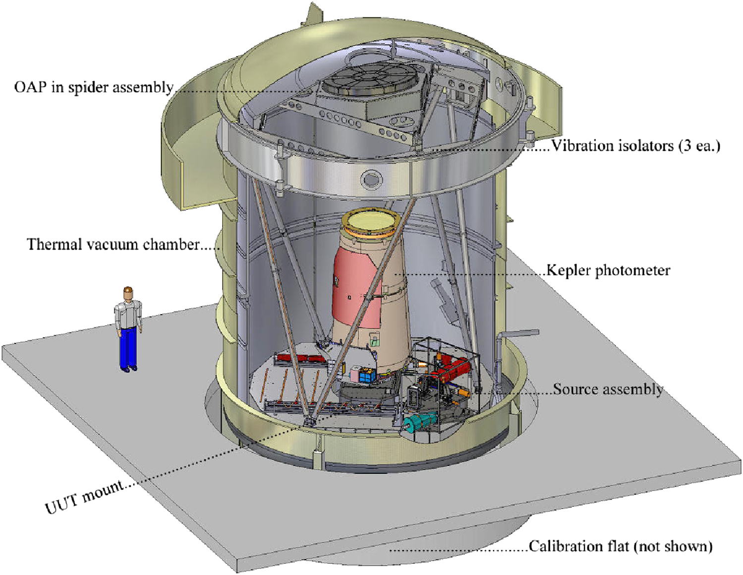 The cryogenic optical alignment and testing of Kepler in the VCA was completed in approximately a 1-month period in Spring 2008. The initial alignment of the primary mirror, the FPAA, and the corrector were determined through image sharpness measurements at several field points, and the primary mirror was adjusted to achieve the best focus, producing the most uniform PSF over the FOV. PSFs were measured at field positions on each of the 42 science CCDs and on each of the four fine guidance sensors. As the final step, the primary mirror was set to a prelaunch position predicted by the integrated system optical/structural/thermal model to give the desired focus at the nominal operating conditions in orbit, primarily accommodating zero-g release. 5.Optimizing In-Flight PerformanceThe in-flight performance of Kepler has vindicated the design and prelaunch expectations.2,18,20,21 Following launch on March 6, 2009 and a 67-day commissioning period, routine science operations commenced on May 13. After the photometer reached its operational thermal equilibrium, analysis of PSFs using the Kepler science star field indicated that the science requirements were being met even before any adjustments were made. Careful measurements using sub-pixel dithering characterized the encircled energy and sharpness metrics across the field and determined that a slight adjustment to the focus would improve the performance and allow significantly more stars to be monitored with the full photometric precision required to detect transits. Following this adjustment the final focus produces 95% encircled energy diameters ranging from 3.2 to 7.5 pixels over the field. The flux in the brightest pixel ranges from 30% to 60%, with an average of 47%. The flux collected is within 1% of predictions based on prelaunch calibrations, indicating that the throughputs and sensitivities of all components are unchanged, and no contamination or other degradation has occurred. Geometrical vignetting is less than 1% within 4.6 deg of center, increasing to about 11% 7 deg off axis, which is beyond the edge of the FPAA. The geometrical mapping of the sky onto the focal plane was calibrated to within 0.1 pixel, allowing the precise placement of the photometric apertures for each target star. One stray light artifact associated with the telescope optics is a faint ghost attributed to reflection of light off of the detectors, then off of the inner surface of the corrector and back to another region of the focal plane. A slight annual variation in diffuse background light is a result of the line-of-sight to Cygnus traversing different amounts of zodiacal dust in our solar system. Analysis of quarterly calibration data, routine engineering data, and the development of new algorithms are continuously enabling better data products. The current state-of-the-art is documented in the Kepler Instrument Handbook.17 In order to support the selection of pixels for downlink associated with each target star,22 the sub-pixel dithered measurements were used to construct a system PSF called the pixel response function23 (PRF). The PRF is used to estimate the pixel values for a star given that star’s location on the focal plane. The PRF is constructed as a collection of piecewise polynomials fit to dithered data in regions of each CCD channel, and is interpolated to determine the PRF at a specified pixel location. As part of the PRF measurement the focal plane geometry was measured in sufficient detail to capture as-built distortions of the Schmidt optical system and the field-flattening lenses. The stability of the flight system, the homogeneity of the large database, and the increasing sophistication of the processing algorithms allows small environmental and instrumental effects to be observed, and when appropriate, corrected. The scientific goal of detecting and characterizing transits of smaller planets with longer orbital periods motivates efforts to operate Kepler in the most efficient and effective manner,24 to improve the data processing pipeline,25 and to communicate the implications of these to the scientists interpreting the data.17,26 A seasonal focus variation was observed as a change in size of the PRF by as much as 10% relative to commissioning, with the largest variation being on channels near the edge of the focal plane. This seasonal variation was shown to be highly correlated with the temperature on the launch vehicle adapter on the bottom of the photometer due to solar impingement (see Fig. 7). These variations are also apparent in plate scale measurements and indicate a small (few microns) change in the focal length of the telescope. Because these variations are seasonal, they occur on a time scale that does not interfere with transit detection. Higher-frequency focus and plate scale variations were also observed early in the mission and were associated with heaters on the spacecraft bus that cycled every few hours. The cycle time of these heaters was comparable to the 13-h transit time scale, which did interfere with transit detection. The set point of these heaters was modified to that they cycled with smaller temperature amplitude and higher frequency to improve transit visibility. Fig. 7Seasonal focus variations are due to solar impingement on the base of the photometer. The top panel shows the relative average pixel response function compared to the commissioning measurement at the start of the mission. Different lines in this plot correspond to the average of different channels. The middle and bottom plot shows the temperature of the primary mirror assembly and the launch vehicle adaptor on the bottom of the photometer. These temperatures are well correlated with the seasonal focus changes. 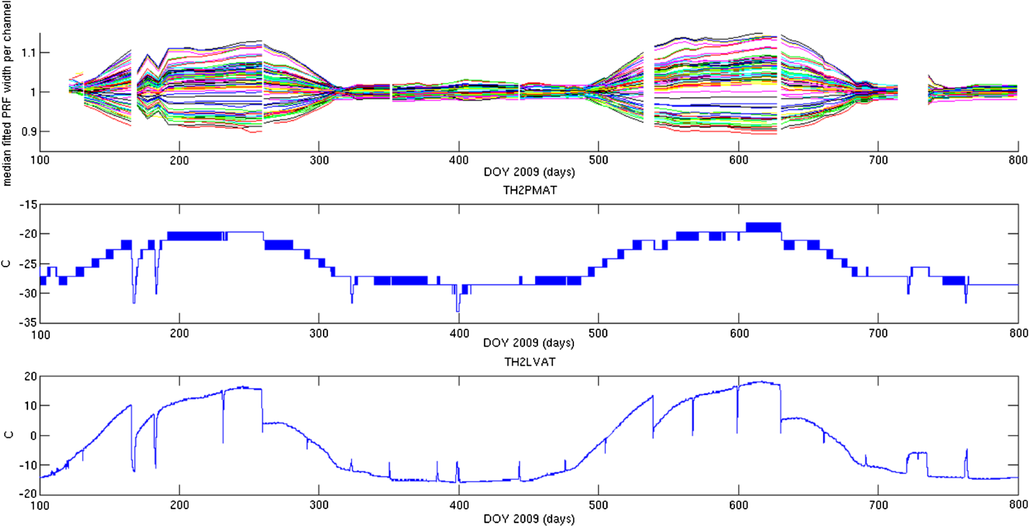 Small electronic effects in the CCD detectors and their local detector electronics create artifacts that could be mistaken for photometric signatures of terrestrial-size planets. They are attributed to video crosstalk between the fine guidance sensors and the science detectors, and to amplifier oscillations. These phenomena have been observed in some of the detector modules, and they are temperature and scene dependent. The detector architecture includes capabilities to obtain various kinds of collateral calibration data, including columns with “bias only” signals, and “serial overscan,” rows with masked pixels and “parallel overscan.” Data are also available from a small number of “artifact removal pixels” in each long cadence, and full frame images and reverse-clocked readouts can be taken occasionally. Algorithms have been developed to identify, flag, and correct science data in regions affected by these recognizable noise patterns.20,27 6.Relevance for Future NASA MissionsKepler is making enormous contributions to NASA’s strategic goals and scientific priorities. The mission has been in continuous operation for over four years, and was recommended for an additional two years of extended mission by NASA’s Senior Review process. The photometer is providing a continuous stream of data for over 156,000 stars with photometric precision averaging 25 ppm. As of January 2013, over 2700 candidate exoplanets have been identified, with several hundred more under close scrutiny. At least 58 candidates appear to be within the Habitable Zones of their stars. Evidence for more than one planet orbiting the same star has been seen in 23% of systems so far. Nearly three quarters of the candidate planets are smaller than Neptune.28 One hundred and five new planets have been definitely confirmed by radial velocity and/or transit timing variations. At least one small rocky planet has been discovered and published.29 In the fields of astrophysics where such precision fuels discoveries, asteroseismology has blossomed into a mature science with oscillation modes diagnosing the internal structure and evolutionary state of thousands of stars.30 Kepler is a model of a moderate-cost mission that is providing stunning scientific insights into the nature of our universe. It is often cited as a paradigm for a “medium strategic mission,” also known as “probe-class.” The science program is competitively selected via an announcement of opportunity process and developed by a principal investigator-led team that may include individuals from many institutions. Implementation of the space element and the ground system is managed by a NASA center. Industry partners assume responsibility for development of most of the hardware. International collaborations are common. Despite the challenges of a large team and perhaps complicated relationships, success can be had. NASA’s portfolio of potential future missions31,32 includes many directed at further study of exoplanets,33 and others addressing the scientific themes of cosmic origins and physics of the cosmos. Budget constraints will limit the number of large strategic “flagship” missions that can be developed, so concepts for achieving the important science goals with probe-class missions similar in size and cost to Kepler are being explored. Future missions such as Wide Field InfraRed Survey Telescope,34 a gravitational wave observatory,35 an X-ray astrophysics observatory,36 and a Cosmic Microwave Background polarization mission37 will all benefit from Kepler’s technological achievements. The large-aperture, wide-FOV telescope, a very large focal plane with integrated fine guidance sensors that allow milliarc second precision pointing, the numerous design features that enable very fine photometric precision and the program management insights gained from years of experience38 all contain valuable lessons learned. AcknowledgmentsThe authors acknowledge the hundreds of scientists, engineers, and managers from NASA Headquarters, Ames Research Center, Jet Propulsion Laboratory, Ball Aerospace & Technologies Corp., L-3 Brashear and Tinsley, the SETI Institute, and many universities whose dedicated efforts over many years created the exquisite observatory that Kepler is today. Funding was provided through the Astrophysics Division of NASA’s Science Mission Directorate. ReferencesW. J. Boruckiet al.,
“Kepler planet-detection mission: introduction and first results,”
Science, 327
(5968), 977
–980
(2010). http://dx.doi.org/10.1126/science.1185402 SCIEAS 0036-8075 Google Scholar
D. G. Kochet al.,
“Kepler mission design, realized photometric performance, and early science,”
Astrophys. J. Lett., 713
(2), L79
–L86
(2010). http://dx.doi.org/10.1088/2041-8205/713/2/L79 AJLEEY 0004-637X Google Scholar
R. L. Gilliland,
“Stellar astrophysics from the Kepler mission,”
in American Astronomical Society meeting 218,
(2011). Google Scholar
W. J. Chaplinet al.,
“The asteroseismic potential of Kepler: first results for solar-type stars,”
Astrophys. J. Lett., 713
(2), L169
–L175
(2010). http://dx.doi.org/10.1088/2041-8205/713/2/L169 AJLEEY 0004-637X Google Scholar
M. D. Still,
“Stellar astrophysics with Kepler from an extended mission baseline,”
in AAS Meeting #220,
(2012). Google Scholar
W. J. Boruckiet al.,
“Kepler: search for earth-size planets in the habitable zone,”
in Proc. IAU Symp.,
289
–299
(2008). Google Scholar
J. F. KastingD. P. WhitmireR. T. Reynolds,
“Habitable zones around main sequence stars,”
Icarus, 101
(1), 108
–128
(1993). http://dx.doi.org/10.1006/icar.1993.1010 ICRSA5 0019-1035 Google Scholar
N. M. Batalhaet al.,
“Selection, prioritization, and characteristics of Kepler target stars,”
Astrophys. J. Lett., 713
(2), L109
–L114
(2010). http://dx.doi.org/10.1088/2041-8205/713/2/L109 AJLEEY 0004-637X Google Scholar
J. M. Jenkinset al.,
“Kepler mission moved: forwarding address 22 m 40 s, ,”
in 37th Division of Planetary Sciences Meeting,
684
(2005). Google Scholar
N. M. Batalhaet al.,
“Optimization of the Kepler field of view,”
in American Astronomical Society meeting 209,
1188
(2006). Google Scholar
T. M. Brownet al.,
“Kepler input catalog: photometric calibration and stellar classification,”
Astron. J., 142
(4), 112
–130
(2011). http://dx.doi.org/10.1088/0004-6256/142/4/112 0004-6256 Google Scholar
R. L. Gillilandet al.,
“Kepler mission stellar and instrument noise properties,”
Astrophys. J. Suppl., 197
(1), 1
–19
(2011). http://dx.doi.org/10.1088/0067-0049/197/1/6 APJSA2 0067-0049 Google Scholar
G. Basriet al.,
“Photometric variability in Kepler target stars: the sun among stars—a first look,”
Astrophys. J. Lett., 713
(2), L155
–L159
(2010). http://dx.doi.org/10.1088/2041-8205/713/2/L155 AJLEEY 0004-637X Google Scholar
V. S. Argabrightet al.,
“The Kepler photometer focal plane array,”
Proc. SPIE, 7010 70102L
(2008). http://dx.doi.org/10.1117/12.789913 PSISDG 0277-786X Google Scholar
J. W. ZinnG. W. Jones,
“Kepler primary mirror assembly: FEA surface figure analysis and comparison to metrology,”
Proc. SPIE, 6671 667105
(2007). http://dx.doi.org/10.1117/12.732667 PSISDG 0277-786X Google Scholar
J. Van CleveD. A. Caldwell,
“Kepler Instrument Handbook, KSCI 19033-001,”
(2009) http://archive.stsci.edu/kepler/ July ). 2009). Google Scholar
D. Ebbetset al.,
“In-flight photometric performance of the 96 Mpx focal plane for NASA’s Kepler exoplanet mission,”
Proc. SPIE, 8146 81460H
(2011). http://dx.doi.org/10.1117/12.897443 PSISDG 0277-786X Google Scholar
M. Martellaet al.,
“Optical testing of the Kepler photometer in a thermal vacuum environment at Ball Aerospace,”
Proc. SPIE, 7436 74360S
(2007). http://dx.doi.org/10.1117/12.830008 PSISDG 0277-786X Google Scholar
D. A. Caldwellet al.,
“Kepler instrument performance: an in-flight update,”
Proc. SPIE, 7731 773117
(2010). http://dx.doi.org/10.1117/12.856638 PSISDG 0277-786X Google Scholar
J. M. Jenkinset al.,
“Initial characterization of Kepler long cadence data for detecting transiting planets,”
Astrophys. J. Lett., 713
(2), L120
–L125
(2010). http://dx.doi.org/10.1088/2041-8205/713/2/L120 AJLEEY 0004-637X Google Scholar
S. T. Brysonet al.,
“Selecting pixels for Kepler downlink,”
Proc. SPIE, 7740 77401D
(2010). http://dx.doi.org/10.1117/12.857625 PSISDG 0277-786X Google Scholar
S. T. Brysonet al.,
“The Kepler pixel response function,”
Astrophys. J. Lett., 713 L97
–L102
(2010). http://dx.doi.org/10.1088/2041-8205/713/2/L97 AJLEEY 0004-637X Google Scholar
M. R. Haaset al.,
“Kepler science operations,”
Astrophys. J. Lett., 713 L115
–L119
(2010). http://dx.doi.org/10.1088/2041-8205/713/2/L115 AJLEEY 0004-637X Google Scholar
J. M. Jenkins,
“Overview of the Kepler science processing pipeline,”
Astrophys. J. Lett., 713 L87
–L91
(2010). http://dx.doi.org/10.1088/2041-8205/713/2/L87 AJLEEY 0004-637X Google Scholar
J. Christiansenet al.,
“Kepler data release notes,”
(2012) http://archive.stsci.edu/kepler/data_release.html Google Scholar
J. J. Kolodziejczaket al.,
“Flagging and correction of pattern noise in the Kepler focal plane array,”
Proc. SPIE, 7742 77421G
(2010). http://dx.doi.org/10.1117/12.857637 PSISDG 0277-786X Google Scholar
W. J. Borucki,
“Characteristics of the Kepler planetary candidates based on the first data set,”
Astrophys. J., 728
(2), 117
(2010). http://dx.doi.org/10.1088/0004-637X/728/2/117 Google Scholar
N. M. Batalhaet al.,
“Kepler’s first rocky planet: KEPLER-10b,”
Astrophys. J., 729
(1), 27
(2011). http://dx.doi.org/10.1088/0004-637X/729/1/27 ASJOAB 0004-637X Google Scholar
R. Gillilandet al.,
“Kepler asteroseismology program: introduction and first results,”
ArXiv eprints, 122
(888), 30
(2009). Google Scholar
R. Blandfordet al.,
“New worlds, new horizons in astronomy and astrophysics,”
(2010) www.nap.edu/catalog/12951.html Google Scholar
P. Hertz,
“Astrophysics implementation plan,”
(2012) http://science.nasa.gov/media/medialibrary/2012/12/20/Rev1-StrategicIImplementationPlan-20Dec2012.pdf Google Scholar
K. Anderson,
“Gravitational Wave Mission Concept Study Final Report,”
(2012) http://pcos.gsfc.nasa.gov/physpag/GW_Study_Rev3_Aug2012-Final.pdf Google Scholar
J. Fansonet al.,
“Management and systems engineering of the Kepler Mission,”
Proc. SPIE, 7738 77380N
(2010). http://dx.doi.org/10.1117/12.859727 PSISDG 0277-786X Google Scholar
Biography Dennis Ebbets is the business development manager for Astrophysics at Ball Aerospace & Technologies Corp., where he has spent 28 years of his career. He has served as a calibration scientist, systems engineer, and member of the Investigation Definition Teams for three science instruments for NASA’s Hubble Space Telescope, and was Ball’s project scientist during the development of the NGST/JWST mission concept. Dennis was the study manager for Origins Probes, Visions Missions, and Astrophysics Strategic Mission Concept Studies. He is a 1978 graduate of the University of Colorado, where he earned a PhD in Astrophysics. He is a frequent speaker at public events, with HST, JWST, and Kepler being among the most popular topics.  Chris Stewart is a project engineer at Ball Aerospace & Technologies Corp., with over 20 years experience in optical engineering and project management. He was the integrated product team manager and lead optical engineer for the Kepler telescope, responsible for cost, schedule, resource, subcontracting, and staffing matters, as well as overseeing the optical engineering efforts during the design, manufacturing, and testing phases. A 1994 graduate of the University of Arizona Optical Sciences program, he has also had key roles with Ball’s JWST and Spitzer programs, and other remote sensing flight and R&D programs.  Peter Spuhler is an optical systems engineer at Ball Aerospace & Technologies Corp., with over 12 years of experience in test and analysis of instruments and telescopes. He characterized the performance of the vertical collimator assembly and developed the procedures for testing Kepler’s optical system in ambient and vacuum environments, and the algorithms and software for analysis of the data. His work on the alignment using parametric phase retrieval and subpixel sampling of encircled energy over the field of view was critical to verifying the system performance before launch. During the commissioning phase he led the focus adjustment and verification that optimized the image quality for sensitivity and noise. A 2001 graduate of the University of Arizona Optical Sciences Center, he has played key roles in other NASA space science programs at Ball, including Deep Impact, HiRiSE, Ralph and OLI.  Paul Atcheson is a staff consultant at Ball Aerospace & Technologies Corp., with 30 years of experience in remote sensing and optical system development. He was the Kepler photometer technical manager responsible for all activities related to integration and verification testing of the science payload. He managed the optical engineering efforts leading to completion of the vertical collimator assembly prior to the photometer system level testing. A 1985 PhD graduate of the University of Arizona Optical Sciences Center, Paul’s experience includes both engineering and management of projects, studies, and proposals working in all phases of the development cycle, from IR&D proof-of-concept through final product integration and qualification.  Jeffrey Van Cleve is an astronomer with the Kepler project at NASA Ames Research Center. His technical interests include the mathematics and logic behind the algorithms used by the Kepler Science Processing Pipeline, and verifying the integrity and quality of the delivered products. He was an author of the Kepler Instrument Handbook and many Data Release Notes, which provide current and future generations of scientists with an understanding of the treasure trove of astrophysical data that Kepler has contributed to the Multimission Archive at the Space Telescope Science Institute. The clarity, accuracy, and completeness of the data and its documentation will provide a legacy that will make it easy for people to analyze and publish the data. Jeff studied physics at Princeton University, and earned his PhD from Cornell. Prior to joining the Kepler team at Ames he worked on the Infrared Spectrometer for the Spitzer Space Telescope at Ball Aerospace.  Stephen Bryson is target scientist for the Kepler mission. He leads the false-positive identification effort and monitors Kepler performance at the pixel level. Prior to joining Kepler in 2005, Steve developed new, high-accuracy numerical methods for solving nonlinear differential equations and participated in the early development of virtual reality. Steve is an avid amateur astronomer, and worked at Chicago’s Adler Planetarium in the late 1970s. He holds a PhD in computational mathematics from Stanford, and has taught modern physics in adult education classes at the San Francisco Academy of Sciences for over 10 years. An active amateur musician/composer, Steve plays piano, organ, guitar, and lute. His compositions have been used in planetarium sky shows and in various web sites, including the Kepler Carl Sagan Essay Contest.  Andrew Clarkson is a 1988 graduate of the University of Rochester. He has over 25 years of experience in the engineering, manufacturing, and management of optical systems for large telescopes at Contraves, Brashear, and L-3 Integrated Optical Systems. He was the Product Line Manager at Brashear responsible for the optics for NASA’s Kepler space mission. He is currently the Director of Optical Engineering and Optics Business Development for L-3, leading optical resources and technology development. |