
|
|
1.IntroductionExtensive researches have been conducted in the past decade on the focusing1–8 and generation1,3,9,10 of cylindrical vector beams both theoretically1,2,4–8 and experimentally.1,3,9,10 Many applications have been reported, e.g., focusing of radially polarized vector beams in probing a tight focal spot1–4 and creating longitudinally polarized nondiffraction beams.5–8 Particularly, generation of subwavelength nondiffraction beams (called “needle of light” by Wang et al.5) has attracted wide interest,6–8,11–18 because such a light beam suits a variety of applications in optical microlithography,19 high density optical data storage,20 or microscopic imaging.21 More importantly, the subwavelength nondiffraction beam with the electric field being longitudinally polarized has potential applications especially in particle acceleration,5,22 optical trapping,5,23 and near-field scanning optical microscopy.1,5 Following the work by Wang et al.5 and again using radially polarized vector beams in free space, Kitamura et al. reported creating a subwavelength beam by focusing a narrow-width annular beam under a high numerical aperture (NA) aplanatic lens system.16 Full width at half maximum (FWHM) of the transverse beam width in the focal plane is about and the extended depth of focus is roughly .16 Under a high aperture () paraboloid mirror system, Dehez et al. further reported suppressing the nondiffraction beam to be in the focal plane and with an ultra-long focal depth of about .17 The tight focusing performance of a high aperture paraboloid mirror was demonstrated by Meixner et al.24 These two methods16,17 generate longitudinally polarized light needles under lens or mirror systems, which are sharper than the result () in Ref. 5; however, the compressed light needles are nonuniform (approximately in a Gaussian shape) within the extended focal depth compared with Ref. 5, and the minimum beam size has only been localized near the focal plane, implies that the created light needles stringently diffracting propagate along the axial direction. Other researches have created either a flattop light needle of beam size broader than 6 or ultra-long light needles with much broader beam size and nonuniform intensity distribution.7,8 All these light needles are of dominantly longitudinal polarization, not purely especially at an out of focal plane. Besides, it is still possible to use some unconventional methods to generate light needles, e.g., using either a plasmonic lens14 or a super-oscillatory lens18; however, these light needles are not longitudinally polarized and nonuniform, either within the near-field region14 or tens of wavelengths away from the element surface.18 So far, a light needle with radial beam size of (FWHM) might have approached the minimum size in free space under conventional far-field lens- or mirror-based systems 5–8,13–17,25; however, at an out of focal plane, the transverse beam size varies largely and the nondiffraction beam oscillates or decays. Above all, generation of pure longitudinally polarized, super-Gaussian light needles of consistent beam size of and arbitrary length has not yet been achieved. As indicated by Wang et al.,5 a balance is difficult to draw among sharpening the beam size, extending the focal depth, homogenizing the axial intensity distribution, and purifying the polarization state. This problem still exists in Refs. 6–8 and 13–18. In this paper, we aim to solve this problem and describe a method to retain the beam size of over an arbitrarily long focal depth. We use an annular paraboloid mirror16,17 and modulate the incident radially polarized beam by the cosine synthesized filter (CSF). CSF is an amplitude filter, which can be designed quite flexibly to reshape the three-dimensional light field. We provide, e.g., light needles with consistent beam size of and super-Gaussian intensity distribution within an axial range of , , , or over , respectively. 2.MethodSuppose a radially polarized beam is incident upon a high NA reflection paraboloid mirror system (Fig. 1), and the radially and longitudinally polarized components of the electric field in the focal region are described, according to the vectorial Debye–Wolf diffraction integral,17,26,27 as and respectively; while for the aplanatic lens system (Fig. 1), the apodization factor changes from to , and Eqs. (1) and (2) become3–5 and respectively. and are constants with respect to (), with and being the wave number and focal length, respectively; is the illumination wavelength; are the zeroth-order and first-order Bessel functions of the first kind; is the maximum semi-angle of the focusing light cone, and is the numerical aperture for an aplanatic lens system in a vacuum. Care should be taken for the sign differences between Eqs. (1), (2) and (3), (4). Equations (1)–(4) are derived from the widely used vectorial Debye–Wolf diffraction integral.2,26,27Fig. 1Focusing a radially polarized Bessel–Gaussian beam in free space, through a reflection paraboloid mirror system (upper right) or a transmission aplanatic lens system (lower right), respectively. The polarization conversions of p- and s-polarized components are marked for comparison. Compression of the radial beam size and elongation of the focal depth are realized by an amplitude pupil filter, which also serves as a special polarization conversion element. 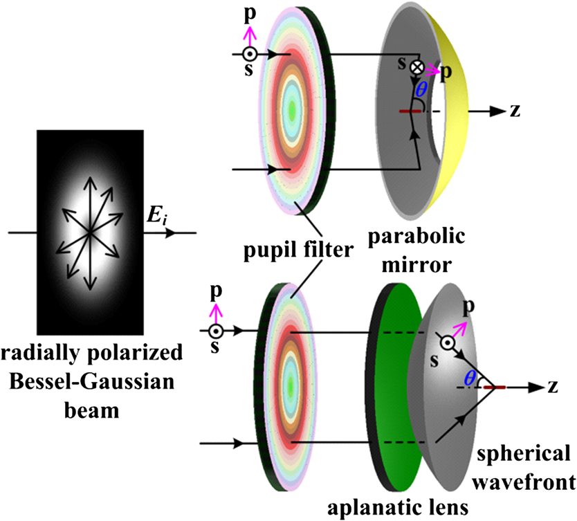 Specifically, consider a radially polarized Bessel–Gaussian beam with the waist plane at the pupil plane of an aplanatic lens system, and the corresponding amplitude of the Bessel–Gaussian beam is expressed as2,5,7 where denotes the ratio of the aperture radius, , to the beam waist, ; is the focusing angle, with ; however, for a paraboloid mirror system, the amplitude distribution with respect to becomes due to the differences of geometric projection relations. We take as unity in the following calculations.5,7 Other radially polarized vector beams, e.g., Laguerre–Gaussian, could be similarly modeled and analyzed.We now turn to reshaping the light field distribution in the focal region of a high aperture paraboloid mirror or aplanatic lens system. In order to create a subwavelength, arbitrarily long light needle with uniform intensity distribution, the CSF is formulized as where and are constructed to separately suppress the radial beam size and elongate the axial focal depth. A variety of super-resolving pupil functions can, in principle, be used to replace 28; for a high aperture paraboloid mirror system, one might simply adopt the most widely used annular pupil filter, equivalently, using an annular beam, or an annular paraboloid mirror. The annular pupil function (or an annular beam) for a paraboloid mirror system, , is mathematically expressed as where denotes the circular function, being unity with , otherwise 0; denotes the minimum focusing semi-angle. The obstruction factor, , is defined as the ratio of the minimum beam radius to the maximum beam radius; specifically, and for a paraboloid mirror system and an aplanatic lens system, respectively. is introduced to compress the radial beam size by suppressing the radially polarized component, (the parasitic energy); as a result, the radial beam size can readily surpass the diffraction limit of half wavelength for . is constructed to uniformly elongate the light field along the axial direction, as7,28 where . According to Euler’s formula, , each cosine sub-term in Eq. (9), , is split into the sum of two conjugate exponential phase functions, . By multiplying with in Eqs. (1) and (2), it yields ; therefore, the fundamental effect of is to decompose the focusing light field into two separate light segments. Such an effect has been successfully used to create a series of light needles in our previous reports,7,28 though with much broader beam size and nonuniform axial intensity distribution.7 The shift factor in , , is to longitudinally shift the decomposed light segments in order to arbitrarily extend the focal depth by coherent superimposition. The balance factor, , is to homogenize the superimposed beam such that a light needle with uniform intensity distribution might be obtained. is a normalization constant to maximize the light throughput.The light field in the focal volume can be calculated by replacing with in Eqs. (1)(2)(3)–(4). The electric energy densities are calculated using , , and . We further calculate the polarization conversion efficiency,5 , defined as the ratio of the longitudinally polarized electric energy to the total energy in the focal plane (), with , and denoting the radius of the central main lobe of . implies that the longitudinally polarized component predominates in the total energy. We compare the radial beam size between a high aperture reflection paraboloid mirror system and a transmission aplanatic lens system with respect to the obstruction factor, , as shown in Fig. 2(a). The radial focal spot has been dramatically compressed for both mirror and lens systems with a large central obstruction, and is much sharper in the paraboloid mirror system for the same focusing angle. FWHM is used to characterize both the radial beam size and axial focal depth, denoted as and , respectively. For NA 0.95 () aplanatic lens system with clear pupil, , , and . (Hence, the radially polarized parasitic energy dominates, as .) While for a reflection paraboloid mirror system of , , , and ; for , parameters are calculated as , , and , respectively. Specifically, the radial focal spot () is much sharper with , and compared with lens in Fig. 2(b) and mirror system in Fig. 2(c), respectively. The polarization conversion efficiency is much higher for the paraboloid mirror system, i.e., the radially polarized component has been highly suppressed, as shown in Fig. 2(e); as a result, the electric field in the focal region is much more longitudinally polarized. Fig. 2Comparisons of the radial beam size between a reflection paraboloid mirror system and a transmission aplanatic lens system. (a) The radial beam size with respect to the obstruction factor for a transmission aplanatic lens system with () (triangle), compared with a reflection paraboloid mirror system with (circle) or (square). The radial focal spots with are plotted in (b), (c), and (d), respectively, and the corresponding radially polarized electric components, , are plotted in (e). The radially polarized component is dramatically suppressed for a high aperture paraboloid mirror system, especially for a large obstruction factor. The diffraction limit, calculated from when , is also plotted for comparison. 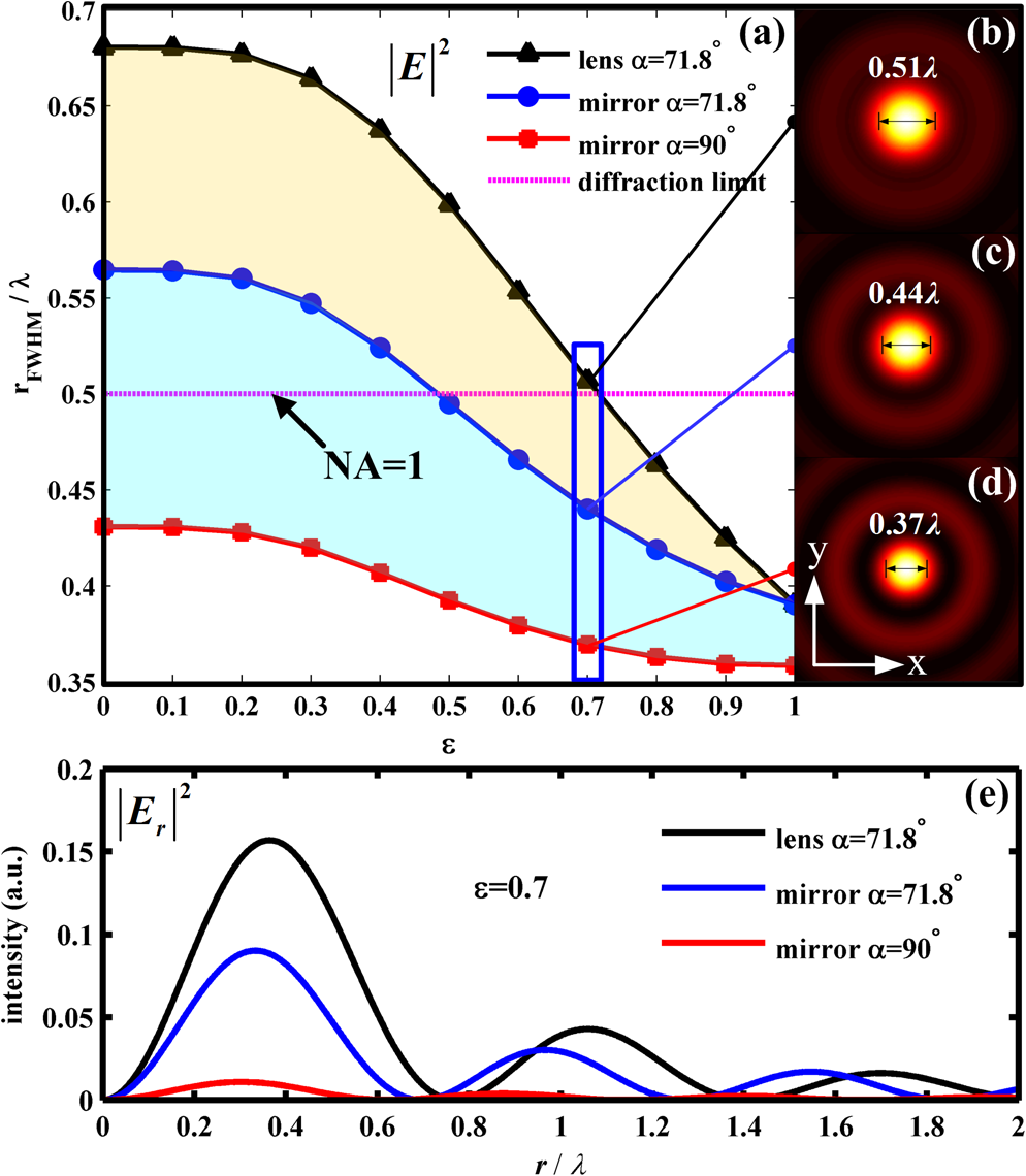 3.Numerical Calculations and ComparisonsFor a high aperture paraboloid mirror system with maximum focusing semi-angle being , light needle with radial beam size of (FWHM) could be uniformly elongated with CSF, e.g., from to over . Within the flattop range of the modulated light needles, the peak-valley intensity fluctuations are all less than 1%. Equations (1), (2), and (6)(7)(8)–(9) are used in the following examples. In order to highly compress the radially polarized component, the obstruction factor is set to be 0.7 for all cases, viz., almost half the area of the incident beam is blocked. It is found through calculations that the radial beam size of the elongated light needle remains , even further increasing . In order to show the proposed method is powerful and quite flexible, variable length light needles over , , , and , are designed, respectively, and the total energy densities, , are plotted in Fig. 3. Corresponding parameters in Fig. 3 () are tabulated in Table 1. The on-axis intensity distributions of the flattop light needles in Fig. 3 can be characterized by a series of super-Gaussian functions with different orders and widths,15 in contrast to the Gaussian shape, which is generated by an annular paraboloid mirror.16,17 Fig. 3Creation of subwavelength flattop light needles of variable length using cosine synthesized filter (CSF) in a high numerical aperture paraboloid mirror system (). Contours of in the plane for light needles over (a) , (b) , (c) , and (d) , respectively, and within the distance the flattop peak-valley intensity fluctuations are all less than 1%. 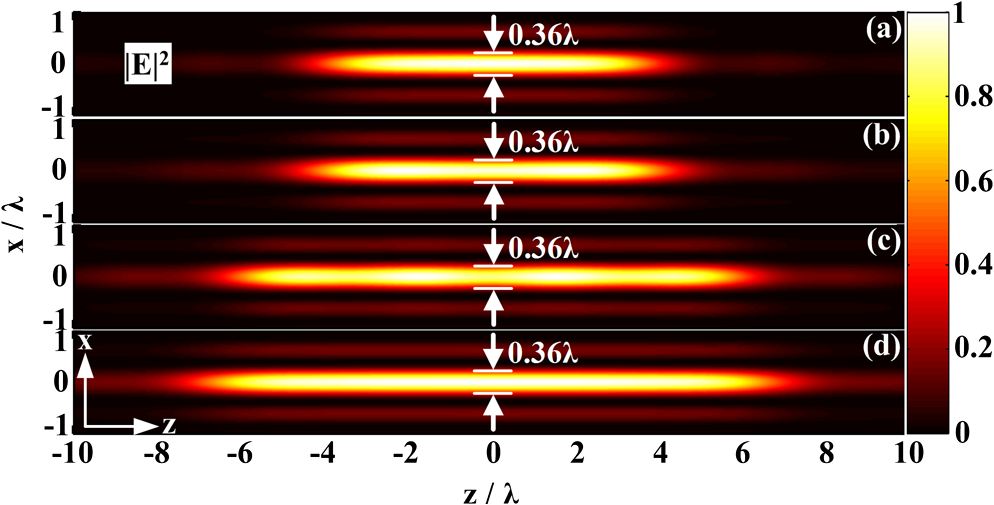 Table 1Parameters of cosine synthesized filter for various length flattop light needles (ε=0.7).
For the light needle in Fig. 3(d), evaluation parameters are calculated as , , , and the flattop peak-valley intensity fluctuation is less than 0.7% within an ultra-long distance of over (Fig. 4), which is propagating without any divergence, as shown in Fig. 4(c) and 4(d), and localized into a small beam area of (area at half intensity). If , e.g., the radial beam size and the beam area are merely 145.8 nm and 0.0164 , respectively. The corresponding amplitude distribution of is plotted in Fig. 4(a), which is valid within [69.984 deg, 90 deg]. Electric energy densities, , , and , are plotted in Fig. 4(b) in the focal plane (), where the radially polarized component almost disappears (see the inset figure). When compared with the previous reports, the light needle (with radial beam size of and as long as ), as shown in Figs. 3(d) and 4(c), is much sharper and remarkably longer than the result (with radial beam size of and as long as )5; again, the light needle is 2.5 times sharper than the report (with radial beam size of ),8 and much more uniform over the whole axial range of (FWHM)8; moreover, the light needle is pure longitudinally polarized () within the flattop range of the light needle in contrast to Refs. 5–8 and 13–18. Lastly, when compared with Ref. 17, in the focal plane, both light needles are localized to be a small beam size of ; however, at an out of focal plane, the light needle, as shown in Fig. 4, remains the beam size of . Such a good balance has not been achieved in Ref. 17. The detail of the polarization state is further plotted in Fig. 4(d). Above all, the modulated light needle keeps the minimum possible beam size among the known reports 5–8,13–18 and draws a good balance among sharpening the beam size, extending the focal depth, homogenizing the axial intensity distribution, and purifying the polarization state. Fig. 4The details of the light needle as shown in Fig. 3(d). (a) Amplitude distribution of , where the central focusing cone of low angle has been blocked (). (b) Electric energy densities, , , and , in the focal plane, where the radially polarized parasitic energy almost disappears (see the inset). (c) Total electric energy density, , along the axial direction corresponding to a nondiffraction propagating light needle without any divergence over an ultra-long distance of . (d) Contour of and the polarization state (pure longitudinal polarized) in the plane. 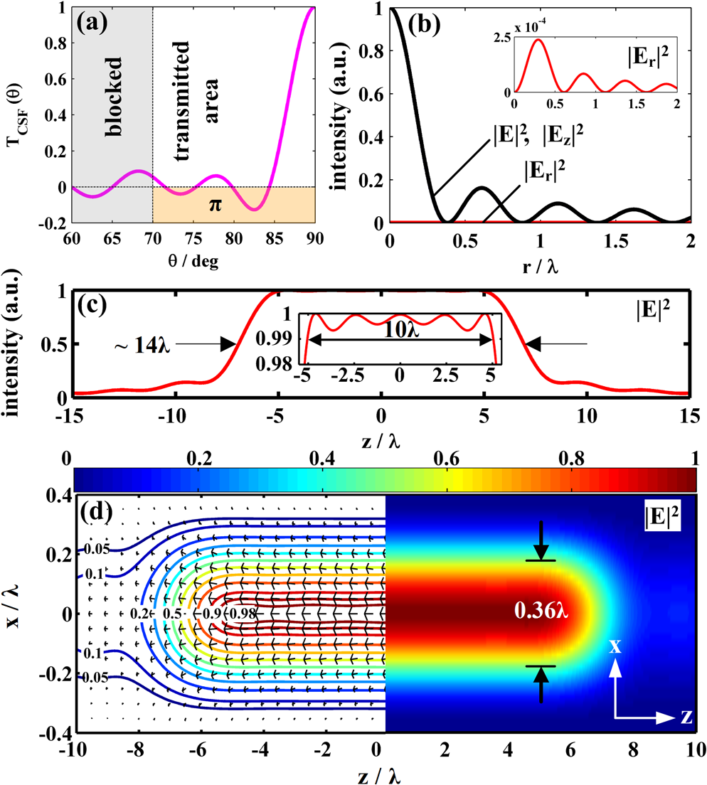 It should be indicated that it is impossible to modulate an ultra-long optical needle from the proposed method. As the theoretical basis, i.e., the vectorial Debye–Wolf interal,26 it is only valid to accurately describe the light field in the vicinity of the focus (far-field approximation condition). According to the previous researches,2,5–8,16,17 the length of the light needle, which can be modulated through the proposed method, could vary from several wavelengths to tens of wavelengths. When the amplitude distribution of the incident radially polarized vector beam changes, the structural parameters of CSF must be re-optimized in the same manner. Practically, there might be two challenges for creating such light needles:24,29 first, a high NA paraboloid mirror with sufficiently high surface accuracy, e.g., peak-valley deviation better than , is required;24 however, this requirement might be alleviated if adaptive optics is introduced to correct the wavefront aberration induced by the imperfection of the fabricated paraboloid mirror; second, accurate realization of the amplitude transmission () depends on the state-of-the-art coating and photolithography techniques;29 alternatively, a method based on binary computer holography might be promising, where a ferroelectric liquid spatial light modulator with accurate binary amplitude modulation is used, and as a result, the accurate vector pupil apodization might be generated.30 4.ConclusionIn conclusion, a method is presented to generate an arbitrary-length super-Gaussian (flattop) optical needle with consistent beam size of (FWHM) and the electric field being pure longitudinally polarized (polarization conversion efficiency greater than 99%). It is realized through modulating the Bessel–Gaussian radially polarized vector beam by the CSF under a reflection paraboloid mirror system with maximum focusing semi-angle of . Numerical calculations show that the on-axis intensity distribution of the modulated light needle is super-Gaussian, in contrast to the subwavelength Gaussian light needle, which is generated by a narrow-width annular paraboloid mirror. Such a light beam may suit several potential applications in particle acceleration, optical trapping, and near-field scanning microscopy.1,5,10 AcknowledgmentsThe authors are grateful to the funding from National Natural Science Foundation of China (NSFC) under Grants Nos. 51275121 and 61008039. ReferencesQ. Zhan,
“Cylindrical vector beams: from mathematical concepts to applications,”
Adv. Opt. Photon., 1
(1), 1
–57
(2009). http://dx.doi.org/10.1364/AOP.1.000001 AOPAC7 1943-8206 Google Scholar
K. S. YoungworthT. G. Brown,
“Focusing of high numerical aperture cylindrical-vector beams,”
Opt. Express, 7
(2), 77
–87
(2000). http://dx.doi.org/10.1364/OE.7.000077 OPEXFF 1094-4087 Google Scholar
R. DornS. QuabisG. Leuchs,
“Sharper focus for a radially polarized light beam,”
Phys. Rev. Lett., 91
(23), 233901
(2003). http://dx.doi.org/10.1103/PhysRevLett.91.233901 PRLTAO 0031-9007 Google Scholar
T. LiuJ. TanJ. Liu,
“Tighter focusing of amplitude modulated radially polarized vector beams in ultra-high numerical aperture lens systems,”
Opt. Commun., 294
(1), 21
–23
(2013). http://dx.doi.org/10.1016/j.optcom.2012.12.006 OPCOB8 0030-4018 Google Scholar
H. Wanget al.,
“Creation of a needle of longitudinally polarized light in vacuum using binary optics,”
Nat. Photon., 2
(8), 501
–505
(2008). http://dx.doi.org/10.1038/nphoton.2008.127 1749-4885 Google Scholar
J. WangW. ChenQ. Zhan,
“Engineering of high purity ultra-long optical needle field through reversing the electric dipole array radiation,”
Opt. Express, 18
(21), 21965
–21972
(2010). http://dx.doi.org/10.1364/OE.18.021965 OPEXFF 1094-4087 Google Scholar
J. Linet al.,
“Achievement of longitudinally polarized focusing with long focal depth by amplitude modulation,”
Opt. Lett., 36
(7), 1185
–1187
(2011). http://dx.doi.org/10.1364/OL.36.001185 OPLEDP 0146-9592 Google Scholar
K. HuZ. ChenJ. Pu,
“Generation of super-length optical needle by focusing hybridly polarized vector beams through a dielectric interface,”
Opt. Lett., 37
(16), 3303
–3305
(2012). http://dx.doi.org/10.1364/OL.37.003303 OPLEDP 0146-9592 Google Scholar
R. Oronet al.,
“The formation of laser beams with pure azimuthal or radial polarization,”
Appl. Phys. Lett., 77
(21), 3322
–3324
(2000). http://dx.doi.org/10.1063/1.1327271 APPLAB 0003-6951 Google Scholar
H. Wanget al.,
“Fighting against diffraction: apodization and near field diffraction structures,”
Laser Photon. Rev., 6
(3), 354
–392
(2012). http://dx.doi.org/10.1002/lpor.201100009 LPRAB8 1863-8880 Google Scholar
H. WangF. Gan,
“High focal depth with a pure-phase apodizer,”
Appl. Opt., 40
(31), 5658
–5662
(2001). http://dx.doi.org/10.1364/AO.40.005658 APOPAI 0003-6935 Google Scholar
H. WangF. Gan,
“Phase-shifting apodizers for increasing focal depth,”
Appl. Opt., 41
(25), 5263
–5266
(2002). http://dx.doi.org/10.1364/AO.41.005263 APOPAI 0003-6935 Google Scholar
H. Wanget al.,
“Subwavelength and super-resolution nondiffraction beam,”
Appl. Phys. Lett., 89
(17), 171102
(2006). http://dx.doi.org/10.1063/1.2364693 APPLAB 0003-6951 Google Scholar
D. Linet al.,
“Subwavelength nondiffraction beam generated by a plasmonic lens,”
Appl. Phys. Lett., 92
(23), 233106
(2008). http://dx.doi.org/10.1063/1.2943274 APPLAB 0003-6951 Google Scholar
T. LiuJ. TanJ. Liu,
“Spoke wheel filtering strategy for on-axis flattop shaping,”
Opt. Express, 18
(3), 2822
–2835
(2010). http://dx.doi.org/10.1364/OE.18.002822 OPEXFF 1094-4087 Google Scholar
K. KitamuraK. SakaiS. Noda,
“Sub-wavelength focal spot with long depth of focus generated by radially polarized, narrow-width annular beam,”
Opt. Express, 18
(5), 4518
–4525
(2010). http://dx.doi.org/10.1364/OE.18.004518 OPEXFF 1094-4087 Google Scholar
H. DehezA. AprilM. Piche,
“Needles of longitudinally polarized light: guidelines for minimum spot size and tunable axial extent,”
Opt. Express, 20
(14), 14891
–14905
(2012). http://dx.doi.org/10.1364/OE.20.014891 OPEXFF 1094-4087 Google Scholar
E.T.F. Rogerset al.,
“Super-oscillatory optical needle,”
Appl. Phys. Lett., 102
(3), 031108
(2013). http://dx.doi.org/10.1063/1.4774385 APPLAB 0003-6951 Google Scholar
H. FukudaR. Yamanaka,
“A new pupil filter for annular illumination in optical lithography,”
Jpn. J. Appl. Phys., 31
(part 1), 4126
–4130
(1992). http://dx.doi.org/10.1143/JJAP.31.4126 JJAPA5 0021-4922 Google Scholar
H. Wanget al.,
“Spot size and depth of focus in optical data storage system,”
Opt. Eng., 4
(6), 065201
(2007). http://dx.doi.org/10.1117/1.2744063 OPEGAR 0091-3286 Google Scholar
R. JuškaitisE. J. BotcherbyT. Wilson,
“Scanning microscopy with extended depth of focus,”
Proc. SPIE, 5701 85
–92
(2005). http://dx.doi.org/10.1117/12.585195 PSISDG 0277-786X Google Scholar
W. D. Kimuraet al.,
“Laser acceleration of relativistic electrons using the inverse Cherenkov effect,”
Phys. Rev. Lett., 74
(4), 546
–549
(1995). http://dx.doi.org/10.1103/PhysRevLett.74.546 PRLTAO 0031-9007 Google Scholar
V. Garces-Chavezet al.,
“Simultaneous micromanipulation in multiple planes using a self-reconstructing light beam,”
Nature, 419
(6903), 145
–147
(2002). http://dx.doi.org/10.1038/nature01007 NATUAS 0028-0836 Google Scholar
J. Stadleret al.,
“Tighter focusing with a parabolic mirror,”
Opt. Lett., 33
(7), 681
–683
(2008). http://dx.doi.org/10.1364/OL.33.000681 OPLEDP 0146-9592 Google Scholar
T. GrosjeanD. Courjon,
“Smallest focal spots,”
Opt. Commun., 272
(2), 314
–319
(2007). http://dx.doi.org/10.1016/j.optcom.2006.11.043 OPCOB8 0030-4018 Google Scholar
B. RichardsE. Wolf,
“Electromagnetic diffraction in optical systems. II. Structure of the image field in an aplanatic system,”
Proc. R. Soc. London Ser. A, 253
(1274), 358
–379
(1959). http://dx.doi.org/10.1098/rspa.1959.0200 PRLAAZ 0080-4630 Google Scholar
M. LiebA. Meixner,
“A high numerical aperture parabolic mirror as imaging device for confocal microscopy,”
Opt. Express, 8
(7), 458
–474
(2001). http://dx.doi.org/10.1364/OE.8.000458 OPEXFF 1094-4087 Google Scholar
T. Liuet al.,
“Creation of subwavelength light needle, equidistant multi-focus, and uniform light tunnel,”
J. Mod. Opt., 60
(5), 378
–381
(2013). http://dx.doi.org/10.1080/09500340.2013.778343 JMOPEW 0950-0340 Google Scholar
F. M. HuangN. I. Zheludev,
“Super-resolution without evanescent waves,”
Nano Lett., 9
(3), 1249
–1254
(2009). http://dx.doi.org/10.1021/nl9002014 NALEFD 1530-6984 Google Scholar
M. A. A. Neilet al.,
“Method for the generation of arbitrary complex vector wave fronts,”
Opt. Lett., 27
(21), 1929
–1931
(2002). http://dx.doi.org/10.1364/OL.27.001929 OPLEDP 0146-9592 Google Scholar
Biography Tao Liu obtained his BS degree in 2007 from Harbin Institute of Technology. Currently, he is a PhD candidate at Harbin Institute of Technology. His research interests are superresolution focusing theory and superresolution confocal microscopy.  Jiubin Tan was awarded the BS, MS, and PhD degrees in 1982, 1988, and 1991, respectively, from the Department of Automation Measurement and Control, Harbin Institute of Technology. In 1995, he became a professor of measurement and instrumentation. He was the former dean of the Department of Automation Measurement and Control. He is currently the director of the Center of Ultra-precision Optoelectronic Instrument Engineering, Harbin Institute of Technology. His research is broad in the fields of ultra-precision measurement and instrumentation.  Jie Lin received his doctorate in optics from Harbin Institute of Technology in 2007. He currently works as an associate professor in the discipline of instrument science and technology at Harbin Institute of Technology. His research interests include optical beam shaping, super-resolution focusing, two-dimensional grating for lithography, binary optical elements, and the optical performance of metal micro/nanostructure.  Jian Liu obtained his BS degree from Southwest Jiaotong University in 1997. He was then awarded the MS and PhD degrees from Harbin Institute of Technology in 2002 and 2009, respectively. In 2012, he became a professor in the Department of Automation Measurement and Control, Harbin Institute of Technology. His research interests are superresolution light microscopy, precision measurement, and metrology. |


