|
|
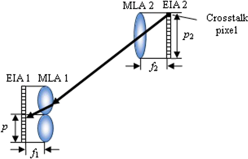
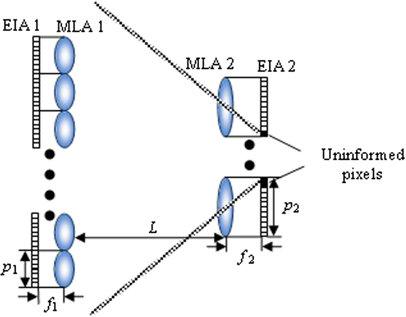
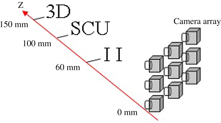
1.IntroductionIntegral imaging (II), which was originally called integral photography, is one of the most attractive techniques in the field of three-dimensional (3-D) displays. It has many advantages over other 3-D display techniques. For example, it provides continuous viewpoints within a specific viewing angle in both horizontal and vertical directions and does not need any special glasses for viewers.1 Compact system configuration is another advantage which makes it a practical alternative to volumetric or holographic 3-D displays. So far, researchers have overcome the problems of low 3-D resolution,2,3 limited depth of field, etc.4–11 How to make the II 3-D display accepted by home users is an urgent issue. In the conventional II, the parameters of micro-lens arrays (MLAs) used in both pickup and display processes should be identical. In practical use, we cannot expect all II 3-D display systems to have MLAs with the same specifications, and we could not prepare various sets of elemental image arrays (EIAs) for different II 3-D display systems. To be an ideal 3-D television technique, we have to make the EIA compatible with different II 3-D display systems for a huge number of home users. The theoretical analysis on scaling rule between the primary and secondary pictures taking was firstly carried out by Okoshi.12 His analysis was based on the assumption that the elemental images (EIs) are not scaled when shifted with respect to the optical axes of the corresponding micro-lenses. Park et al. discussed the scaling effects of the optical parameters difference between the pickup and display processes.13 They showed that the lateral magnification is given by the micro-lens size ratio and the longitudinal magnification is given by the focal length ratio. Then, they proposed a ratio-conserving scaling to eliminate distortion of the 3-D image in which the EIAs are scaled using the focal length ratio.14 But these methods cannot cope with a change in the number of micro-lenses. The EIAs obtained in the pickup process are digitally analyzed and full 3-D information of the object are extracted, and then the extracted 3-D information is transmitted to display systems, whose numbers and parameters of micro-lenses are entirely different for the pickup process.15 However, stereo matching is needed to detect the disparity between two or more EIs and the quality of the generated 3-D image will be degraded. The scaling was also achieved by controlling the spatial ray sampling rate of EIA in the pickup process16 and a digital magnification method using interpolation theory was proposed to increase the spatial ray sampling.17 The intermediate-view reconstruction technique using the same interpolation theory was used to increase the number of EIs (Ref. 18). But the parameters of the micro-lens are not changed in these techniques. Smart pixel mapping algorithm is proposed by Martínez-Corral et al.19 to resolve the pseudoscopic problem of the reconstructed 3-D image, which is also resolved by Jung et al. recently.20 In this paper, we propose an II without image distortion using MLAs with different specifications in the pickup and display processes. The deduced pixel mapping algorithm not only resolves the pseudoscopic problem, but also generates the EIA with different lens specifications, and the reconstructed 3-D images do not have any distortions. 2.Principle of the Proposed IIFigure 1 shows the schematic of the proposed II which has different specifications of MLAs in the pickup and display processes. In the pickup process, as shown in Fig. 1(a), the MLA and the EIA are called MLA 1 and EIA 1, respectively. The pitch and the focal length of MLA 1 are and , respectively, and MLA 1 contains micro-lenses. EIA 1 is recorded on the rear focal plane of MLA 1 and the pitch of EIA 1 is the same with that of MLA 1. In the display process, as shown in Fig. 1(b), the MLA and the EIA are called MLA 2 and EIA 2, respectively. The pitch and the focal length of MLA 2 are and , respectively, and MLA 2 contains micro-lenses. EIA 2 generated by the pixel mapping algorithm has different specifications from EIA 1, and the 3-D image reconstructed by EIA 2 and MLA 2 maintains the original size and location of the 3-D object without any distortions. Fig. 1Schematic of the proposed II using MLAs with different specifications in (a) pickup and (b) display processes. 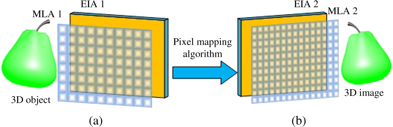 Figure 2 shows the schematic of the proposed pixel mapping algorithm which includes the virtual display process and the virtual pickup process. Since the pickup process and the virtual display process form the standard configuration of II, EIA 1 and MLA 1 reconstruct a 3-D image that maintains the original size and location of the 3-D object, but with the reversed depth. But the pseudoscopic problem can be resolved by the pixel mapping algorithm because the combination of the virtual display process and the virtual pickup process is a modified version of the two-step pickup process. In the virtual pickup process, MLA 2, which is the same as the one used in the display process in Fig. 1(b) and which has different specifications from MLA 1, picks up the depth-reversed 3-D image. The distance between MLA 1 and MLA 2 is . EIA 2 that has different specifications from EIA 1 can be obtained on the rear focal plane of MLA 2, and EIA 2 and MLA 2 have the same pitch of . The resolutions of EIs in EIA 1 and EIA 2 are both . Fig. 2Schematic of the proposed pixel mapping algorithm. (a) Virtual display process and (b) virtual pickup process. 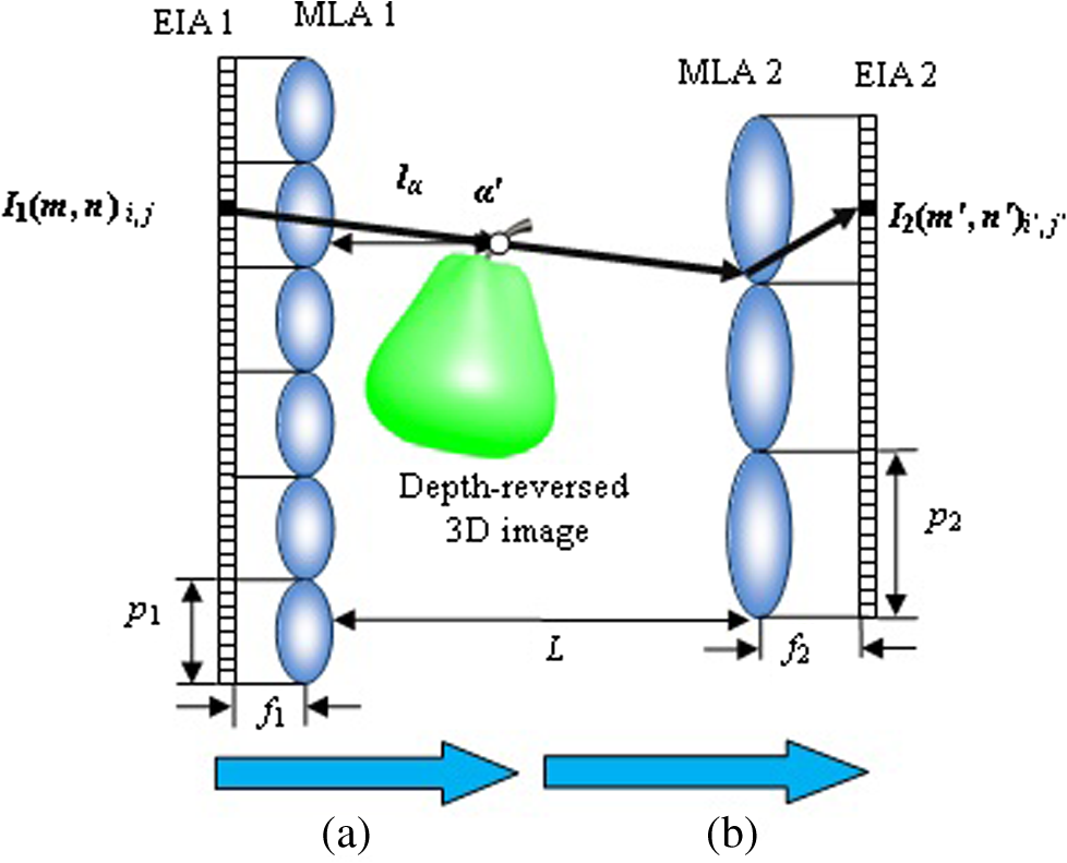 In practicae, the virtual display and virtual pickup processes are carried out by mapping all the pixels in EIA 1 to EIA 2 through the following mathematical relationships. As shown in Fig. 2, in the ’th row and the ’th line EI of EIA 1, a pixel in the ’th row and the ’th line is denoted as . The rays emitted from the pixel are refracted by the micro-lenses in MLA 1 and MLA 2, and then arrive at the ’th row and the ’th line pixel of the ’th row and the ’th line EI in EIA 2. The pixel in EIA 2 is denoted as . EIA 2 can be generated by using the following mathematical relationships: where the function round rounds a number to the nearest integer. When or is bigger than , the pixel should be abandoned to eliminate the overlapping between adjacent EIs. In this way, in loop from 1 to , from 1 to , from 1 to , and from 1 to , all the pixels in EIA 1 are mapped to the rear focal plane of MLA 2, and an EIA 2 that has different specifications from EIA 1 is generated.The distance between MLA 1 and MLA 2 determines the depth of the reconstructed 3-D image. Assuming that in the pickup process, the distance between the 3-D object and MLA 1 is , the depth of the reconstructed 3-D image in the display process is When , the 3-D image will be displayed on the MLA 2 plane, and when or , the 3-D image will be displayed behind or in front of the MLA 2 plane. When the light rays emitted from the pixel in the adjacent EI in EIA 1 are refracted by MLA 1 and MLA 2 and arrive at EIA 2, the crosstalk pixel is produced, as shown in Fig. 3. So the pitches and the focal lengths of MLA 1 and MLA 2 should satisfy Eq. (7) to avoid the crosstalk pixel The uninformed pixel will be caused when pixels in EIA 2 have no corresponding pixels in EIA 1, as shown in Fig. 4. So the numbers of EIs in EIA 1 and EIA 2, and , should satisfy Eqs. (8) and (9) to avoid the uninformed pixels where the function rounds a number to the largest integer.3.Experiments and ResultsIn this experiment, a 3-D scene which consists of three plane images with different depths is built up as shown in Fig. 5. A camera array is used to simulate MLA 1. The -axis shows the distances between the characters and the camera arrays, and they are 60, 100, and 150 mm, respectively. Three experiments using the proposed II, conventional II without scaling, and straightforward scaling II in Ref. 11 are carried out. The specifications of MLA 1 and MLA 2 are listed in Table 1 in which the parameters of MLA 1 and MLA 2 in the proposed II satisfy the relationships in Eqs. (7)–(9). Three EIAs 2 obtained using the three II methods are shown in Figs. 6(a), 6(b), and 6(c), respectively. Table 1Specifications of MLAs 1 and 2 in the experiments.
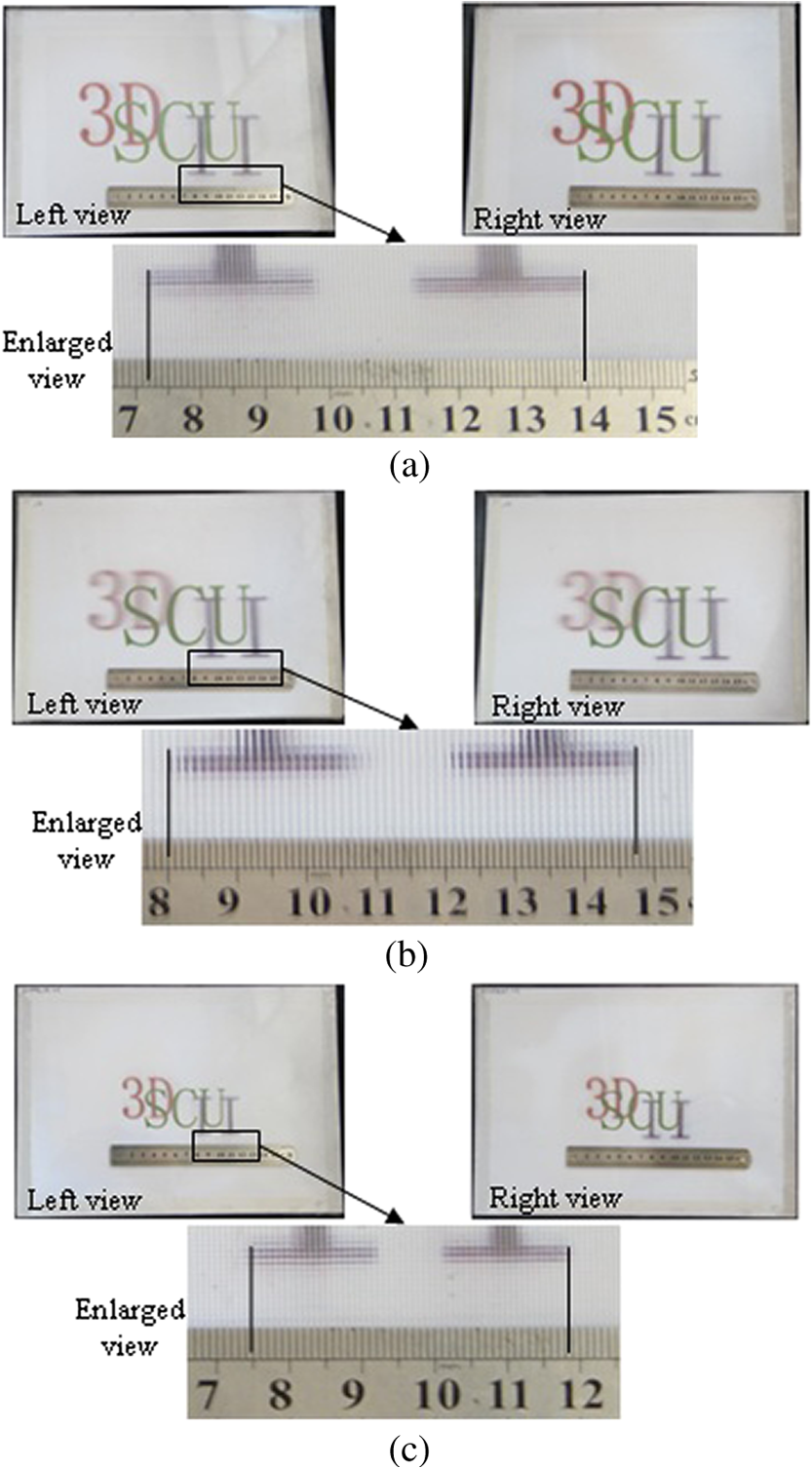
Fig. 6EIAs 2 generated by the (a) proposed II, (b) conventional II without scaling, and (c) straightforward scaling II. 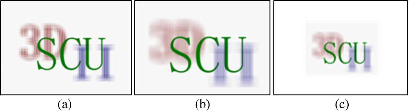 The depth-based computational II reconstruction is implemented to reveal explicitly the cross sections of the reconstructed 3-D images along the longitudinal direction, so that the longitudinal magnification of the 3-D image can be readily determined. Since the distance between MLA 1 and MLA 2 is 100 mm, the reconstructed undistorted 3-D images should be located at the depths of , 0, and 40 mm, respectively. As shown in Figs. 7(a) and 7(b), the 3-D images reconstructed by our proposed II have the same depths without the pseudoscopic problem as the ones reconstructed by the conventional II and their longitudinal magnifications are both 1. However, using the straightforward scaling II as shown in Fig. 7(c), the reconstructed 3-D images have the longitudinal magnification of . Fig. 73-D images at different depths reconstructed by the (a) proposed II, (b) conventional II without scaling, and (c) straightforward scaling II. 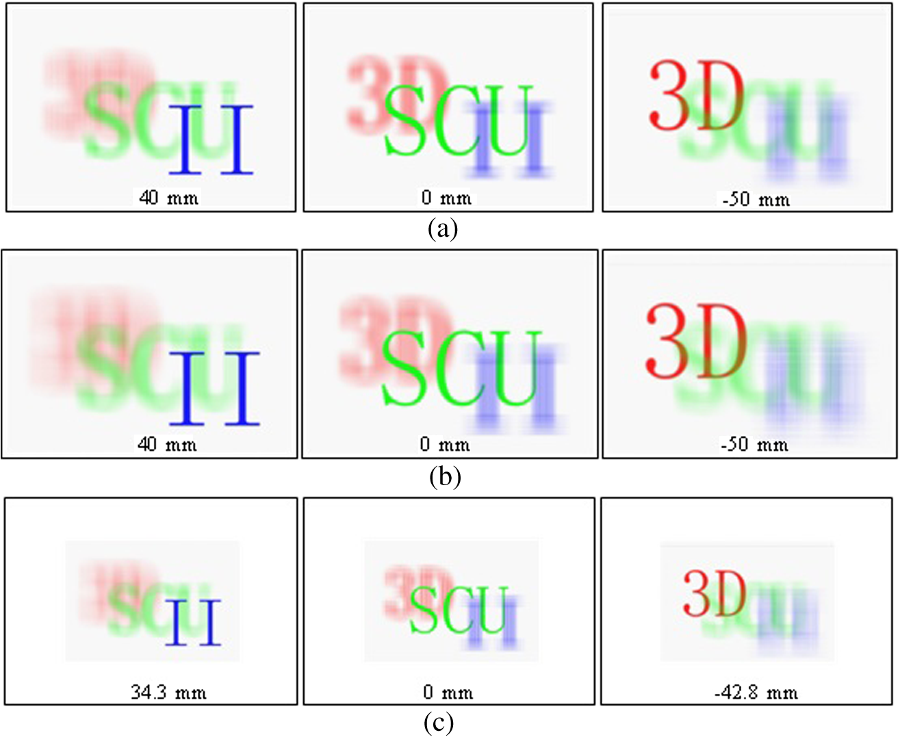 The optical II 3-D display experiments are carried out to verify the lateral magnifications of the reconstructed 3-D images. Since the total resolution of each EIA 2 is pretty high, a high-resolution color printer, EPSON STYLUS PHOTO 1390, is used to print three EIAs 2. Three MLAs 2 are used to match with the three printed EIAs 2 and three II 3-D pictures are obtained as shown in Fig. 8. A ruler is used to measure the lateral size of the reconstructed 3-D images. As shown in Figs. 8(a) and 8(b), the lateral sizes of the characters “II”s reconstructed by our proposed II and the conventional II without scaling are both 67.5 mm. However, using the straightforward scaling II as shown in Fig. 8(c), the lateral size of the reconstructed characters “II” is 43.5 mm. So the lateral magnifications of the proposed II are 1 and the lateral magnification of the straightforward scaling II is about . 4.ConclusionsIn this paper, we propose an II in which MLA 1 in the pickup process and MLA 2 in the display process have different specifications. The pixel mapping algorithm that functions as a converter to transmit the pixels from EIA 1 to EIA 2 not only resolves the pseudoscopic problem but also generates the EIA with different lens specifications. We also deduce the mathematical relationship between EIAs 1 and 2, and the relationships between the parameters of EIAs 1 and 2, and between MLAs 1 and 2. As long as the parameters of MLA 1 and MLA 2 satisfy the relationships in Eqs. (7)–(9), the parameters of MLA 2 and EIA 2 can be selected arbitrarily, hence different EIAs 2 can be generated from EIA 1 for different II 3-D display systems. The experimental results demonstrate that the reconstructed 3-D images in the proposed II maintain the original lateral and longitudinal sizes of the 3-D object without any scaling and distortion. The proposed II could be an ideal candidate for 3-D television broadcasting in the future. AcknowledgmentsThe work is supported by the “973” Program under Grant No. 2013CB328802, the NSFC under Grant Nos. 61225022 and 61036008, and the “863” Program under Grant Nos. 2012AA011901 and 2012AA03A301. ReferencesX. Xiaoet al.,
“Advances in three-dimensional integral imaging: sensing, display, and applications,”
Appl. Opt., 52
(4), 546
–560
(2013). http://dx.doi.org/10.1364/AO.52.000546 APOPAI 0003-6935 Google Scholar
H. Navarroet al.,
“Non-homogeneity of lateral resolution in integral imaging,”
J. Disp. Technol., 9
(1), 37
–43
(2013). http://dx.doi.org/10.1109/JDT.2012.2225018 JDTEDS 0193-2691 Google Scholar
F. JinJ. S. Jang,
“Effects of device resolution on three-dimensional integral imaging,”
Opt. Lett., 29
(12), 1345
–1347
(2004). http://dx.doi.org/10.1364/OL.29.001345 OPLEDP 0146-9592 Google Scholar
J. Wanget al.,
“Enhanced depth of field in integral imaging for 3D display with a cubic phase plate coded camera array,”
J. Disp. Technol., 8
(10), 577
–581
(2012). http://dx.doi.org/10.1109/JDT.2012.2203583 JDTEDS 0193-2691 Google Scholar
J. S. JangF. JinB. Javidi,
“Three-dimensional integral imaging with large depth of focus by use of real and virtual image fields,”
Opt. Lett., 28
(16), 1421
–1423
(2003). http://dx.doi.org/10.1364/OL.28.001421 OPLEDP 0146-9592 Google Scholar
C. G. Luoet al.,
“Depth calculation method of integral imaging based on Gaussian beam distribution model,”
J. Disp. Technol., 8
(2), 112
–116
(2012). http://dx.doi.org/10.1109/JDT.2011.2165831 JDTEDS 0193-2691 Google Scholar
X. WangH. Hua,
“Theoretical analysis for integral imaging performance based on microscanning of a microlens array,”
Opt. Lett., 33
(5), 449
–451
(2008). http://dx.doi.org/10.1364/OL.33.000449 OPLEDP 0146-9592 Google Scholar
M. ChoB. Javidi,
“Optimization of 3D integral imaging system parameters,”
J. Disp. Technol., 8
(6), 357
–360
(2012). http://dx.doi.org/10.1109/JDT.2012.2189551 JDTEDS 0193-2691 Google Scholar
X. Jiaoet al.,
“Dual-camera enabled real-time three-dimensional integral imaging pick-up and display,”
Opt. Express, 20
(25), 27304
–27311
(2012). http://dx.doi.org/10.1364/OE.20.027304 OPEXFF 1094-4087 Google Scholar
H. YangJ. XiaB. Wang,
“Computational reconstruction three-dimensional object using integral imaging,”
in The 1st International Conference on Information Science and Engineering (ICISE2009),
512
–515
(2009). Google Scholar
F. Wuet al.,
“High-optical-efficiency integral imaging display based on gradient-aperture pinhole array,”
Opt. Eng., 52
(5), 054002
(2013). http://dx.doi.org/10.1117/1.OE.52.5.054002 OPEGAR 0091-3286 Google Scholar
T. Okoshi,
“Optimum design and depth resolution of lens-sheet and projection-type three-dimensional display,”
Appl. Opt., 10
(10), 2284
–2291
(1971). http://dx.doi.org/10.1364/AO.10.002284 APOPAI 0003-6935 Google Scholar
J. H. Parket al.,
“Analysis of viewing parameters for two display methods based on integral photography,”
Appl. Opt., 40
(29), 5217
–5232
(2001). http://dx.doi.org/10.1364/AO.40.005217 APOPAI 0003-6935 Google Scholar
J. H. Parket al.,
“Scaling of three-dimensional integral imaging,”
Jpn. J. Appl. Phys., 44
(1A), 216
–224
(2005). http://dx.doi.org/10.1143/JJAP.44.216 JJAPA5 0021-4922 Google Scholar
J. H. Parket al.,
“Three-dimensional display scheme based on integral imaging with three-dimensional information processing,”
Opt. Express, 12
(24), 6020
–6032
(2004). http://dx.doi.org/10.1364/OPEX.12.006020 OPEXFF 1094-4087 Google Scholar
Y. W. SongB. Javidi,
“3D object scaling in integral imaging display by varying the spatial ray sampling rate,”
Opt. Express, 13
(9), 3242
–3251
(2005). http://dx.doi.org/10.1364/OPEX.13.003242 OPEXFF 1094-4087 Google Scholar
R. P. Díazet al.,
“Digital magnification of three-dimensional integral images,”
J. Disp. Technol., 2
(3), 284
–291
(2006). http://dx.doi.org/10.1109/JDT.2006.878772 JDTEDS 0193-2691 Google Scholar
D. C. Hwanget al.,
“Magnification of 3D reconstruction images in integral imaging using an intermediate-view reconstruction technique,”
Appl. Opt., 45
(19), 4631
–4637
(2006). http://dx.doi.org/10.1364/AO.45.004631 APOPAI 0003-6935 Google Scholar
M. Martínez-Corralet al.,
“Formation of real, orthoscopic integral images by smart pixel mapping,”
Opt. Express, 13
(23), 9175
–9180
(2005). http://dx.doi.org/10.1364/OPEX.13.009175 OPEXFF 1094-4087 Google Scholar
J. H. JungJ. KimB. Lee,
“Solution of pseudoscopic problem in integral imaging for real-time processing,”
Opt. Lett., 38
(1), 76
–78
(2013). http://dx.doi.org/10.1364/OL.38.000076 OPLEDP 0146-9592 Google Scholar
Biography Huan Deng is a lecturer of optics at the School of Electronic and Information Engineering, Sichuan University. She received her PhD degree from Sichuan University in 2012. She has published more than 10 papers. She is a member of the Society for Information Display. Her recent research interest is information display technologies including three-dimensional (3-D) displays.  Fei Wu is working toward the PhD degree in optical engineering from the School of Electronics and Information Engineering, Sichuan University, China. His recent research interest is information display technologies including 3-D displays.  Da-Hai Li is a professor of optics at the School of Electronics and Information Engineering, Sichuan University. He received his MS degree from the University of Electronic Science and Technology of China in 1996 and his PhD degree from Sichuan University in 2002, respectively. He has published more than 60 papers. His recent research interests include optics and optoelectronics, especially display technologies and optical measurements.  Qiong-Hua Wang is a professor of optics at the School of Electronics and Information Engineering, Sichuan University, China. She was a postdoctoral research fellow at the School of Optics/CREOL, University of Central Florida, from 2001 to 2004. She received her MS and PhD degrees from the University of Electronic Science and Technology of China (UESTC) in 1995 and 2001, respectively. She worked at UESTC from 1995 to 2001, and at Philips Mobile Display Systems, Philips Shanghai, in 2004. She has published more than 180 papers on display devices and systems. She holds five US patents and 30 Chinese patents. She is a senior member of the Society for Information Display. Her recent research interests include optics and optoelectronics, especially display technologies. |