|
|
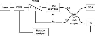
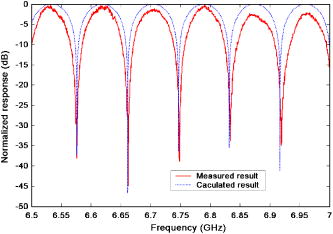
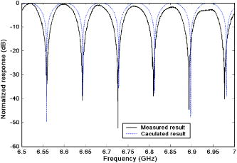
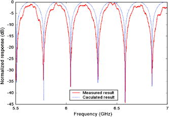
1.IntroductionAll-optical processing of microwave and millimeter-wave signals provides advantages such as large time-bandwidth products, insensitivity to electromagnetic interference, and light weight. A very useful component in radio frequency (rf) systems is a high-resolution tunable notch filter. A number of photonic microwave filters have been reported in the literature.1, 2, 3, 4, 5 In this application, it is required to achieve optically incoherent summing of two light beams. To overcome the optical coherence problem, either a laser array is used,1 or the coherence length of the light source is kept smaller than the minimum delay time of the filter.2 Incoherent summing has also been achieved by using a Hi-Bi fiber3; however, such a filter cannot be tuned easily and needs a long Hi-Bi fiber for small free spectral range (FSR) values. A step tunable design with a tunable laser and uniform Hi-Bi gratings is reported in Ref. 4. A continuously tunable design using a Hi-Bi chirped grating has been reported in Ref. 5; unfortunately, the grating causes a very large chromatic dispersion, which will affect the system performance; the operating wavelength range is also limited due to the fiber Bragg grating bandwidth; moreover, phase noise will be introduced by the crosstalk when the chirped grating is tuned. In this paper, we demonstrate a tunable microwave-photonic filter based on a variable polarization beamsplitter (PBS), a Hi-Bi coupler, and a variable time delay line. The configuration is free from the problems of optical coherence interference and chromatic dispersion. An expression for the filter transfer function is derived and measured results are presented to demonstrate the filter operation. A notch rejection greater than is obtained. It is shown that the notch frequency is continuously tunable by tuning the time delay line. The scheme can operate over a wide range of optical carrier frequencies, restricted only by the bandwidth of the various optical components in the system. 2.System Configuration and Operation PrincipleThe filter configuration is shown in Fig. 1. An rf signal drives an intensity electro-optic modulator (EOM), which modulates the output of a distributed-feedback laser with linewidth. The output of the EOM, which has a Hi-Bi pigtail, is launched into a variable PBS, which also has Hi-Bi pigtails. A quarter-wave plate is inserted in port 1 of the PBS; this enables one to change the power-split ratio in the two output arms of the PBS that have orthogonal states of polarization. One of the output arms of the PBS incorporates a time delay line with a Hi-Bi pigtail and is connected to a Hi-Bi coupler through a fiber of length . The time delay line can provide a tunable time delay, from , with a resolution, between the two output arms of the PBS. The other output arm of the PBS is connected to the Hi-Bi coupler through a fiber of length . The time delay line (OZ Optics Ltd.) has an insertion loss of about . The quarter-wave plate and the variable PBS ensure that equal optical power is incident on the input ports of the coupler; this leads to a strong notch in the filter response. The Hi-Bi coupler combines the two input signals that are orthogonally polarized. One output port of the Hi-Bi coupler is connected to a photodetector and a vector network analyzer. The other output port of the Hi-Bi coupler is connected to an optical spectrum analyzer (OSA). While the OSA is not essential to the operation of the filter, it helps in monitoring incoherent operation of the filter. The differential time delay between the two branches of the resulting filter consists of two parts: one caused by the length difference between and and the other caused by the time delay provided by the time delay line. The transfer function of the microwave filter can be described as: where is the pulse amplitude factor, is the responsivity of the photodiode, is the time delay introduced by the time delay line, and . As explained earlier, the time delay between the two arms of the PBS iswhere is the fixed time delay. Further, the notch frequencies are given by:When one changes the value of time delay , the FSR varies according to Eq. 3.3.Experiment ResultsCase 1. The length difference between and is about and is zero. So the fixed time delay value is about . As shown in Fig. 2, a filter with an FSR of and notch depths more than is obtained. Figure 2 also includes the results calculated using Eq. 1. The calculated and measured results match very well. Moreover, the optical power monitored by the OSA that is connected to the other output port of the coupler is very stable, which means that the operation is free from the problem of optical coherence. Case 2. and are the same as in Case 1; is about . Figure 3 shows the measured and calculated results. The measured FSR is about . The difference between the measured and calculated FSR is less than 4%; this difference comes in because of a slight error in the estimate of the fixed time delay, and because the variable time delay line is set manually. Case 3. The length difference between and is about and is zero. So the calculated fixed time delay reduces to . As shown in Fig. 4, a filter with an FSR of is obtained. The measured results match very well the calculated results. One of the advantages for the design shown in Fig. 1 is that it can easily give much smaller FSR values using short fiber lengths. In comparison, using a design based on Hi-Bi fiber,3 in one of the experiments performed by us, a -long Panda Hi-Bi fiber is needed for achieving an FSR of . 4.ConclusionWe demonstrate a tunable microwave-photonic filter based on a variable PBS, a Hi-Bi coupler, and a variable time delay line. The configuration is free from the problems of optically coherent interference and chromatic dispersion. Measured results show a notch rejection greater than ; also, the notch frequency is continuously tunable by adjusting the time delay line. By using a time delay line with a larger tuning range of time delay values, the tuning range of the notch frequency can be extended further. The scheme can yield small FSR values without needing long Hi-Bi fiber lengths and can operate over a wide range of optical carrier frequencies. AcknowledgmentThe project was partially supported by Open Fund of Key Laboratory of OCLT, BUPT, Ministry of Education, P. R. China. ReferencesD. Pastor and
J. Capmany,
“Fibre optic tunable transversal filter using laser array and linearly chirped fibre grating,”
Electron. Lett., 34 1684
–1685
(1998). https://doi.org/10.1049/el:19981144 0013-5194 Google Scholar
E. H. W. Chan,
K. E. Alameh, and
J. A. R. Minasian,
“Photonics bandpass filters with high skirt selectivity and stopband attenuation,”
J. Lightwave Technol., 20 1962
–1967
(2002). https://doi.org/10.1109/JLT.2002.804018 0733-8724 Google Scholar
W. Zhang,
J. A. R. Williams, and
I. Bennion,
“Optical fiber delay line filter free of limitation imposed by optical coherence,”
Electron. Lett., 35 2133
–2134
(1999). https://doi.org/10.1049/el:19991445 0013-5194 Google Scholar
W. Zhang,
J. A. R. Williams, and
I. Bennion,
“Polarization synthesized optical transversal filter employing high birefringence fiber gratings,”
IEEE Photonics Technol. Lett., 13 523
–525
(2001). https://doi.org/10.1109/68.920773 1041-1135 Google Scholar
X. Yi,
C. Lu,
“Continuously tunable microwave photonics filter design using high birefringence linear chirped grating,”
IEEE Photonics Technol. Lett., 15 754
–756
(2003). https://doi.org/10.1109/LPT.2003.809979 1041-1135 Google Scholar
|