|
|
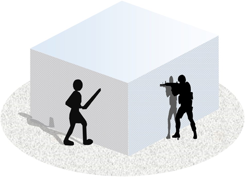
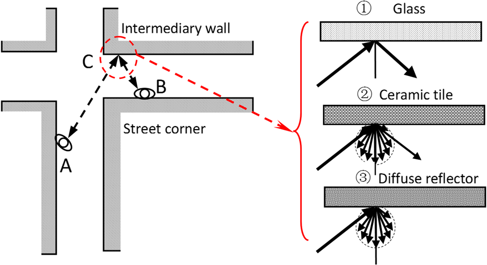
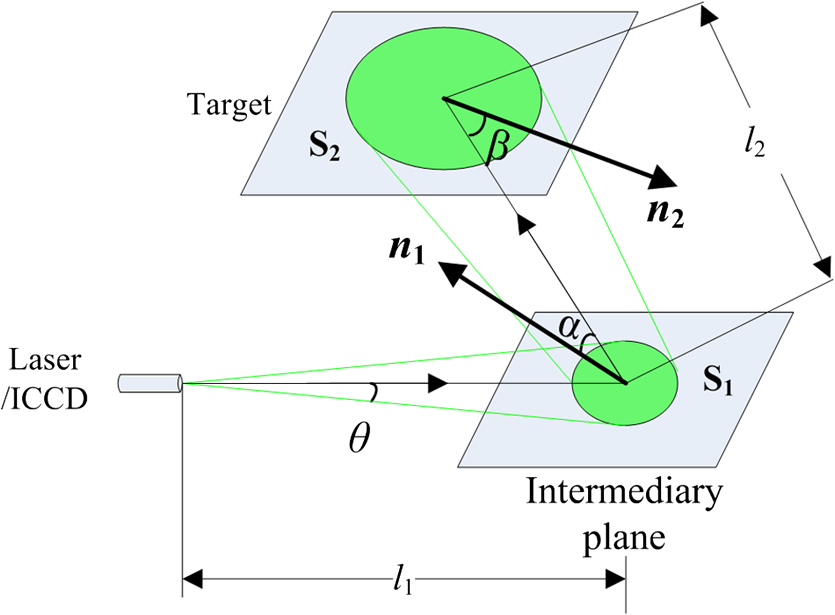
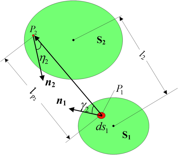
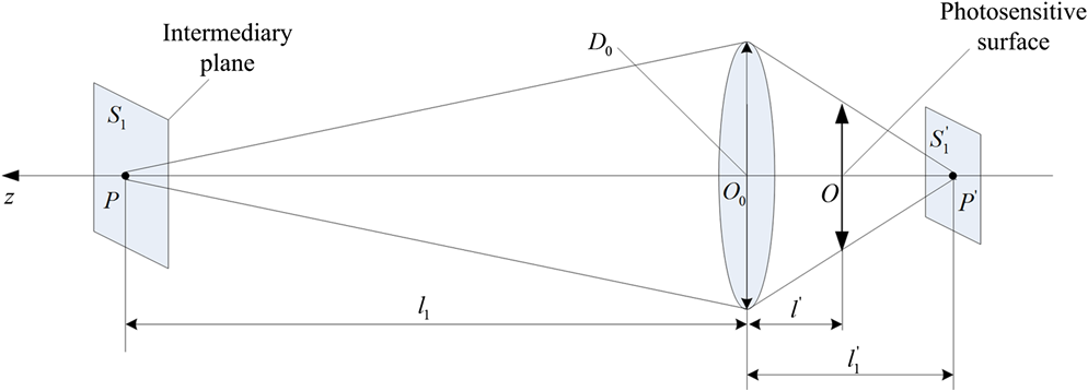
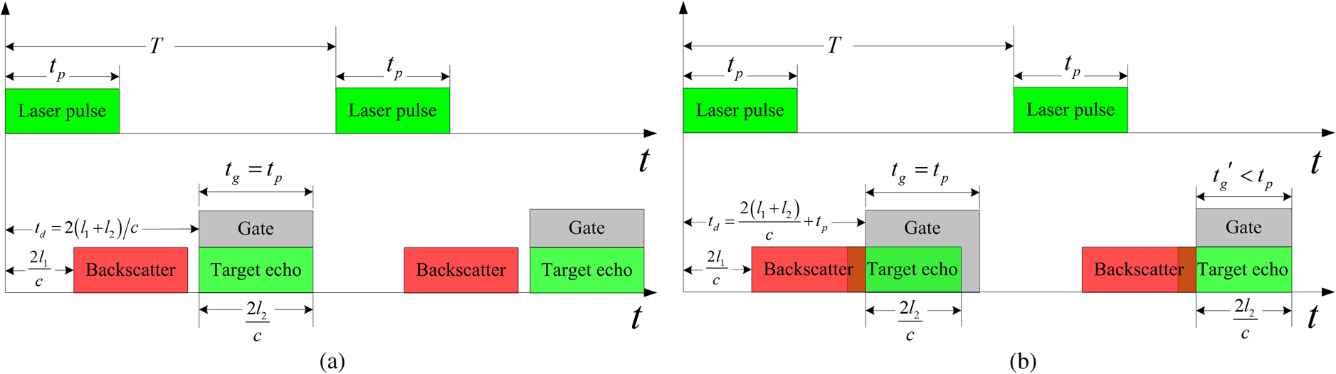
1.IntroductionLaser range-gated imaging can penetrate a strong scattering medium and capture the image of an object at a certain distance by applying active laser illumination, changing the gate delay time, and varying the gate width. It has been widely used in areas such as military reconnaissance, monitoring, underwater detection, and search and rescue. For cases when the line of sight is blocked by corners of walls or other building obstructions within the environment of city streets and buildings (as shown in Fig. 1), traditional imaging techniques and equipment are unable to achieve imaging beyond the direct field of view. Non-line-of-sight imaging can bypass the corners of walls or other obstructions to achieve imaging beyond the direct field of view, which can be used to reduce casualties in modern urban street fighting, and to increase battlefield awareness and operational efficiency. In 2006 and 2007, researchers at the Research Institute for Optronics and Pattern Recognition of Germany and Swedish Defence Research Agency (FOI)1,2 of Sweden carried out joint research on short-wavelength infrared laser range-gated imaging for ground applications in monostatic and bistatic configurations. A number of test targets (test panels, vehicles, and soldiers with weapons) were included in the tests, and windows in buildings and cars, traffic signs, and vehicle surfaces were utilized as the intermediary reflective surfaces. In 2011, the FOI group3 proposed the loss factor model through further study of the effect of the characteristics (including the shape and the reflection characteristics) of the intermediary reflective surface on laser illuminance attenuation and measured the loss factors with different intermediary reflective surfaces. Though their work was insightful, their model is not effective for describing the imaging process. Since 2007, the Media Lab at the Massachusetts Institute of Technology (MIT)4 has been studying transient imaging based on femtosecond laser range-gated imaging technology and proposed an algorithm for extracting object information from multireflection, realizing a means of seeing around the corner. In 2012, researchers at MIT5 realized a three-dimensional reconstruction of hidden targets utilizing diffuse reflections of ultrashort laser pulses using an intermediary reflective surface. Since 2012, researchers at the Beijing Institute of Technology (BIT)6,7 have been studying non-line-of-sight imaging. The BIT group uses a nanosecond laser range-gated imaging system to realize non-line-of-sight imaging of an USAF 1951 standard target at different distances with glass and ceramic tile as the respective intermediary reflective surfaces. These existing researches show the potential application prospects of non-line-of-sight imaging in areas such as urban warfare, counter-terrorism, and disaster relief. Since non-line-of-sight imaging based on laser range-gated imaging is affected not only by the parameters of the laser range-gated imaging system but also by the reflection characteristics of the intermediary reflective surface and the scene, construction of an optical imaging model is important to the development and application of non-line-of-sight imaging. This paper describes the construction of an image contrast model of non-line-of-sight imaging from the viewpoint of a two-dimensional illumination distribution on the photosensitive surface, in order to analyze the performance of a non-line-of-sight imaging system utilizing a laser range-gated imaging system and to provide a theoretical basis for actual non-line-of-sight imaging system design. 2.Principle of Non-Line-of-Sight ImagingThe key to non-line-of-sight imaging is to make it possible to see a street-corner target or an indoor target by utilizing an intermediary reflective surface, as illustrated in Fig. 2. A is the observer, B is the target under observation, and C is the intermediary reflective surface. B is outside the range of objects that can be directly imaged by A, so that C is utilized to realize non-line-of-sight imaging of target B. A laser range-gated imaging system, consisting of a nanosecond laser and an intensified charged coupled device (ICCD) imaging system, is located at location A. The ICCD imaging system is focused on location B. The beam from the nanosecond laser from location A experiences first-order reflections (consisting of first-order specular reflection and first-order diffuse reflections, where the first-order diffuse reflection contains first-order backscattering and first-order forward-scattering) at the intermediary reflective surface C. The first-order specular reflection and first-order forward-scattering illuminate target B and then are reflected at target B in a Lambertian fashion (the second-order reflection). First-order backscattering is received by the ICCD imaging system, forming a defocused image and reducing the image contrast of target B. The second-order Lambertian reflection strikes the intermediary reflective surface C and experiences third-order reflections (consisting of third-order specular reflection, third-order backscattering, and third-order forward-scattering) at location C. Third-order specular reflection is received by the ICCD imaging system, forming a focused image of target B. Like the first-order backscattering, the third-order forward-scattering is also received by the ICCD imaging system, reducing the contrast of the image of target B. For certain intermediary reflective surfaces (like ceramic tile), the effective target signal illuminance (third-order specular reflection) may be overwhelmed by the first-order backscattering and third-order forward-scattering, resulting in the target being undetectable. The first-order backscattering is apparently larger than the third-order forward-scattering, so the first-order backscattering is the dominant factor reducing the contrast of the image of target B. Thus, a better non-line-of-sight image of target B can be obtained by filtering out the first-order backscattering, which can be realized by laser range-gated imaging. Meanwhile, an image intensifying technique is also needed because the effective target signal illuminance (third-order specular reflection) is typically weak. The intermediary reflective surface is also a very important factor in non-line-of-sight imaging, which can be generalized to include a full specular reflector like glass (1), a partial specular reflector like ceramic tile (2), and an ideal diffuse surface (3). The study in this paper is mainly carried out on intermediary reflective surface types 1 and 2. Construction of an optical imaging model of the non-line-of-sight imaging process, which is based on the parameters of the intermediary reflective surface, the parameters of the laser range-gated imaging system, and the properties of the target, is vital for the theoretical analysis and system design of non-line-of-sight imaging based on laser range-gated imaging. This model assumes that the imaging will occur at night or in low-light conditions to reduce the impact of environmental illuminance. 3.Image Contrast Model of Non-Line-of-Sight ImagingAs shown in Fig. 3, the laser beam is projected onto an intermediary reflective surface forming the light spot and experiences first-order reflections; then the first-order reflections are projected onto the target forming light spot . The distance from the laser to the geometric center of is . The distance from the geometric center of to the geometric center of is . The vector tracing the direction of the incident light from to makes an angle with (the vector normal to ) and an angle with (the vector normal to ). The optical axis of the laser and the optical axis of the ICCD are assumed to be coincident, and the divergence angle of the laser and the field view angle of the ICCD are also assumed to be coincident. In this section, the laser transmission characteristics (attenuation and distribution) in the non-line-of-sight imaging process will be analyzed. 3.1.Pulsed Laser and Range-Gated Imaging SystemThe illuminance of the pulsed laser can be written as shown in Eq. (1), where denotes the transmission power of the pulsed laser, is the propagation time, is the energy of a single pulse, is the pulse width, is the solid angle of the divergence of the laser beam, and is half divergence angle of the laser beam. The function is described by Eq. (3). The detector includes pixels, is the gate width, and is the strobe gating delay time.3.2.Reflection Characteristics of the Intermediary Reflective SurfaceThe reflection characteristics (consisting of specular reflection characteristics and diffuse reflection characteristics) of the intermediary reflective surface are among the important factors that can influence the non-line-of-sight imaging results. Without loss of generality, the intermediary reflective surface is assumed to be free of absorption, so that its reflection characteristics can be described by the specular reflectivity and the diffuse reflectivity . is a constant, obeys Lambertian reflection, and . The reflectance distribution function is described by with3.3.Target Signal Illuminance and Disturbance Caused by the Intermediary Reflective Surface under CW-Laser Illumination3.3.1.Illuminance on the target planeThe illuminance on the target plane is denoted as , which consists of two parts: is caused by the first-order specular reflection of the laser and is caused by the first-order forward-scattering. The illuminance on should be obtained first. First-order specular reflectionThe area illuminated on by the laser first-order specularly reflected by can be written as Therefore, can be calculated as The target distance is equal to the sum of and . If is much larger than the square root of , and is illuminated by the vertically incident laser beam (), Eq. (8) can be further simplified. First-order forward-scatteringTo facilitate the analysis and calculations, Fig. 3 is expanded along the optical path. Assuming that the optical axis of the laser coincides with the optical axis of the ICCD imaging system, a Cartesian coordinate system is established with the geometric center of the lens as the Cartesian coordinate origin. The optical axis is along the axis, and the axis and the axis are, respectively, parallel to the detector array’s length and width directions, as is shown in Fig. 4. is the angle between the axis and the projection of on the plane, and points in the direction opposite to the direction of the axis. and are, respectively, projections of the laser beam on the intermediary reflective surface and on the target. According to the geometric relationship, the projection equations for and on the plane are, respectively, given by and are random points, respectively, on and , and is a microsurface element around (as shown in Fig. 5). is the illuminance on caused by . The illuminance is inversely proportional to the square of the distance as in Eq. (11), where is the angle between vectors and and is the angle between vectors and .Therefore, In summary, 3.3.2.Target signal illuminance on the photosensitive surfaceAssuming that the target plane and the photosensitive surface of the laser range-gated imaging system are conjugate object plane and image plane, and that is much larger than , the illuminance on the photosensitive surface caused by the scene can be expressed as Eq. (17), where is the luminance on ( is the reflectance of the target or background, for or ), denotes the F-number, is the aperture diameter, and is the spectral transmittance of the objective lens.3.3.3.Disturbance illuminance on the photosensitive surface caused by scattering of the intermediary reflective surfaceThe disturbance illuminance on the photosensitive surface caused by scattering of the intermediary reflective surface consists of two parts: (third-order forward-scattering) and (first-order backscattering). Since the intermediary reflective surface is not on the target plane, each point on corresponds to a diffuse plaque on the photosensitive surface, and the diffuse plaque can be expressed by a point spread function. A Cartesian coordinate system is established with the geometric center of the lens as a Cartesian coordinate origin. is the intersection of the intermediary reflective surface and the axis, and ’ is the image point of , as shown in Fig. 6. According to geometrical optics, the center of the diffuse plaque for point on is given by whereThe radius of the diffuse plaque can be written as where is the aperture diameter and is the refractive index of the object space.The point spread function of the diffuse plaque for point can be expressed as withFirst-order backscattering illuminance on the photosensitive surfaceAccording to Eq. (21), the first-order backscattering can be expressed as withis the solid angle defined by the rays emanating from point to the aperture defined by the lens. In fact, since the distances between the camera and every point on are not the same, the value of for each of the points is not the same. As the laser divergence angle is very small, an approximate treatment for is made here. Third-order forward-scattering illuminance on the photosensitive surfaceIn Fig. 5, is a microsurface element around . is the illuminance on caused by . The illuminance is inversely proportional to the square of the distance as expressed in Eq. (25), where is the angle between vectors and and is the angle between vectors and . Then we obtain Since can be calculated as the illuminance on the photosensitive surface caused by can be written asIn summary, 3.4.Image Contrast Model of Non-Line-of-Sight ImagingNon-line-of-sight imaging can be achieved with laser range-gated imaging with a pulsed laser; therefore it is necessary to make a distinction between third-order reflection and first-order backscattering. 3.4.1.Illuminance on the photosensitive surface under pulsed laser illuminationUnder pulsed laser illumination, the illuminance on the photosensitive surface caused by a single pulse is a function of time . 3.4.2.Signal and noise under pulsed laser illuminationConsidering the time sequence of the laser range-gated imaging system and the discrete nature of the detector unit, the illuminance on the detector unit caused by the target and background within a pulse period can be calculated as where and are the length and width of the detector unit, respectively.The illuminance on the detector unit caused by scattering of the intermediary reflective surface can be expressed, respectively, as We simplify the imaging system noise and environmental noise by combining them into an equivalent incident illuminance , which is used as shown in the following equation: The total disturbance of the non-line-of-sight imaging system can be expressed as 3.4.3.Apparent contrast of the image on a photosensitive surfaceThe apparent contrast of the image on a photosensitive surface can be described by where denotes the averaged signal of the target and background, denotes the inherent contrast ratio, and is the contrast transfer function.3.4.4.Analysis and discussionIn addition to systematic noise, the scattered disturbance illuminance from the intermediary reflective surface is the main factor in image quality degradation.
can be totally filtered out by setting the strobe gating delay time to . An optimum contrast image can be obtained if the gate width is simultaneously reduced to . However, utilization rate of the laser illuminance decreases with increase of . The laser range-gated imaging system cannot receive the target signal illuminance with , and the efficiency decreases to 0. Since the laser range-gated imaging itself is low-signal-to-noise ratio (SNR) imaging, sacrificing the laser illuminance efficiency significantly reduces the SNR of the image. Therefore, practical application of non-line-of-sight imaging with laser range-gated imaging requires careful balance of the overall system. 4.Imaging Characteristic Analysis of Non-Line-of-Sight ImagingBased on the image contrast model of non-line-of-sight imaging constructed above, this section analyzes the non-line-of-sight imaging results with different intermediary reflective surfaces. Typical parameters of non-line-of-sight imaging with a laser range-gated imaging system are shown in Table 1. The imaging depth of field is 36 m with a laser pulse width of 120 ns and a gate width of 120 ns; 40 laser pulses are received by the photodetector within a frame when the imaging frame rate is 25 fps and the laser pulse frequency is 1000 Hz, so that a laser illuminance equivalent to 4.8 μJ is received by the photodetector per frame. Table 1Parameters of non-line-of-sight imaging with the laser range-gated imaging system.
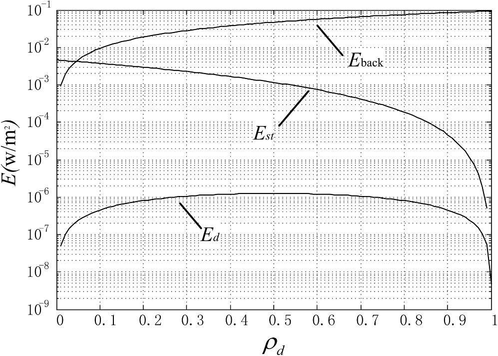
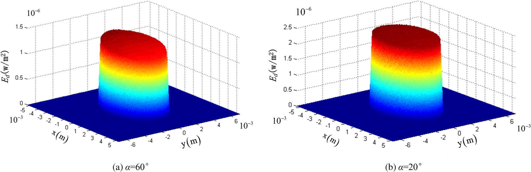
4.1.Impacts of Reflection Characteristics of the Intermediary Reflective Surface on Non-Line-of-Sight ImagingThe impacts of the reflection characteristics of the intermediary reflective surface on non-line-of-sight imaging are considered with , , and . Since ·, the target signal illuminance and first-order backscattering are separable. Figure 8 shows the curves of the target signal illuminance , the first-order backscattering , and the third-order forward-scattering for different values of the diffuse reflectivity of the intermediary reflective surface with a CW laser. Since and are unevenly distributed over the imaging field, the and in Fig. 8 are the respective means of and in the center area of the imaging field. The curves in Fig. 8 indicate the following conclusions:
4.2.Impacts of the Location of the Intermediary Reflective Surface and the Gate Width on Non-Line-of-Sight ImagingThe parameter is chosen to be equal to to fully use the laser illuminance and to reduce the noise for a typical laser range-gated imaging system, in which case the imaging depth of field is ·. The gate opens when the echo signal reaches the detector, so that the gate delay time equals . The following discussion is based on the assumption that is equal to 0. Figure 10 shows a plot of the image contrast versus distance with and . The plot shows that first decreases with and then increases with to a certain constant value at when is totally separated from and that finally is nearly fixed with increasing . Figure 11 shows a plot of the image contrast versus distance with and . The plot shows that increases with and that obtains its maximum value when is totally filtered out at . 5.ConclusionsThis paper describes the construction of an image contrast model of non-line-of-sight imaging with a laser range-gated imaging system on the basis of the modeling of an intermediary reflective surface. The image contrast model analyzes three factors affecting the image contrast of non-line-of-sight imaging with different intermediary reflective surfaces, where the three factors are target signal illuminance, first-order backscattering, and third-order forward-scattering. A non-line-of-sight imaging experiment simulation was carried out with the parameters of an actual laser range-gated imaging system. The simulation results show that (1) the first-order backscattering is the dominant disturbance to non-line-of-sight images and can be effectively filtered out by laser range-gated imaging and (2) the effect of the third-order forward-scattering on non-line-of-sight images is often negligible since the third-order forward-scattering is insignificant compared to the target signal illuminance in most cases. The image contrast model of non-line-of-sight imaging with a laser range-gated imaging system gives insights into the theoretical analysis and system design of non-line-of-sight imaging. The simulation results also show that the reflection characteristics of the intermediary reflective surface have a significant effect on non-line-of-sight imaging. The bidirectional reflectance distribution function (BRDF) is a more comprehensive description of surface reflection characteristics; thus, BRDF modeling of typical construction material surfaces is a direction for further research. Meanwhile, since non-line-of-sight imaging with laser range-gated imaging system is usually low-SNR imaging, estimating the range of non-line-of-sight imaging using MRC or TTP is another direction for further research. AcknowledgmentsThis work was supported by the Specialized Research Fund for the Doctoral Program of Higher Education (No. 20111101110013) and the Foundation of the Science and Technology on Low-Light-Level Night Vision Laboratory (No. J20110504). The authors would like to thank all the reviewers for their helpful comments and constructive suggestions. They would also like to thank Mr. Ye Peng and Dr. Xuan Hongwen for their assistance with the programming. ReferencesE. Repasiet al.,
“Mono- and bi-static SWIR range-gated imaging experiments for ground applications,”
Proc. SPIE, 7114 71140D
(2008). http://dx.doi.org/10.1117/12.799816 PSISDG 0277-786X Google Scholar
E. Repasiet al.,
“Advanced short-wavelength infrared range-gated imaging for ground applications in monostatic and bistatic configurations,”
Appl. Opt., 48
(31), 5956
–5969
(2009). http://dx.doi.org/10.1364/AO.48.005956 APOPAI 0003-6935 Google Scholar
O. SteinvallM. ElmqvistH. Larsson,
“See around the corner using active imaging,”
Proc. SPIE, 8186 818605
(2011). http://dx.doi.org/10.1117/12.893605 PSISDG 0277-786X Google Scholar
A. Kirmaniet al.,
“Looking around the corner using transient imaging,”
in IEEE 12th Int. Conf. on Computer Vision,
159
–166
(2009). Google Scholar
O. Guptaet al.,
“Reconstruction of hidden 3D shapes using diffuse reflections,”
Opt. Express, 20
(17), 19096
–19108
(2012). http://dx.doi.org/10.1364/OE.20.019096 OPEXFF 1094-4087 Google Scholar
X. Kai-daet al.,
“Survey on technical development and combined application mode of laser range-gated imaging system,”
Infrared Technol., 34
(1), 16
–23
(2012). Google Scholar
X. Kaidaet al.,
“Non-line-of-sight imaging based on laser range-gated imaging technology,”
Infrared Laser Eng., 41
(8), 2073
–2078
(2012). Google Scholar
J. Wei-qiet al.,
“A model to predict range performance of imaging system for extended target based on minimum resolvable contrast,”
Acta Optica Sinica, 29
(6), 1552
–1556
(2009). http://dx.doi.org/10.3788/AOS 0253-2239 Google Scholar
G. Arthur,
“Prediction and measurement of minimum resolvable contrast for TV sensors,”
Proc. SPIE, 2223 533
–542
(1994). http://dx.doi.org/10.1117/12.177942 PSISDG 0277-786X Google Scholar
R. H. Vollmerhausenet al.,
“New metric for predicting target acquisition performance,”
Opt. Eng., 43
(11), 2806
–2818
(2004). http://dx.doi.org/10.1117/1.1799111 OPEGAR 0091-3286 Google Scholar
BiographyKaida Xu received his BS from Mechanical Engineering College, China, in 2001. He is currently pursuing his PhD in optical engineering at Beijing Institute of Technology, China. His technical interests include low-level-light and infrared imaging technology. Weiqi Jin received his PhD in optical engineering from Beijing Institute of Technology of China in 1990. He is currently a professor with the Department of Optical Engineering in the School of Optoelectronics at the Beijing Institute of Technology. His major research interests include low-level-light imaging, thermal imaging, and image processing. He is a fellow of SPIE. Shenyou Zhao received his BS in control technology and instrument from Changchun University of Science and Technology in 2011. He is currently pursuing his master’s degree in optical engineering at Beijing Institute of Technology, China. His main technical interest is optical imaging technique. Jing Liu received her BS in optical engineering from Beijing Institute of Technology of China in 2009. She studied augmented reality in Universidad Politecnica de Madrid of Spain from March to September 2009. She is currently pursuing her PhD in optical engineering at Beijing Institute of Technology of China. Her technical interests include underwater imaging, laser range-gated imaging, polarization imaging, and imaging process. Hui Guo received her PhD in optical engineering from Beijing Institute of Technology in 2005. She is currently a doctoral supervisor in the National Key Laboratory of Science and Technology on Low Light Level Night Vision, Xi’an, China. Her major research direction is low-light-level night vision technology. Su Qiu received his PhD from School of Optoelectronics at Beijing Institute of Technology in 2013. He is currently an assistant professor in School of Optoelectronics at Beijing Institute of Technology. His major research interests include digital image processing, low-level-light and infrared imaging technology. |