
|
|
1.IntroductionOptical fibers are most commonly used for routing of signals over long distances (meter to kilometer), meanwhile planar devices are the technology of choice for millimeter to centimeter distances. However, for applications involving routing or combining of signals at centimeter to meter distances, optical fibers can be used, but it is expected that routing will involve centimeter to millimeter bending radii. These dimensions are common for routing of signals inside handheld-size devices as well as for routing signals between multiple devices in laboratory-size environments. For silica-based fibers, high-power beam-delivery over centimeter to meter distances and the induced bend loss limits have already been studied.1 Characterization of the losses associated with bending for fibers that transmit high-power beams in the mid- or long-wave infrared ranges has been much more limited. We focus on the mid-infrared range where there are multiple applications such as biomedical, sensing, and defense. There are multiple material systems that could provide infrared optical transmission over short distances such as metal coated hollow waveguides, hollow core fibers, fluoride and chalcogenide fibers.2 However, investigations on the bending radii for many of these systems reduce their attractiveness to short-distance routing. For example, the onset of significant bending losses for core fibers varies with bending diameters of in fluoride fibers,3,4 in metal-coated hollow guides (with 530-μm bore, and higher for smaller bores),5 and 300 mm for hollow core inhibited coupling fibers.6 Chalcogenide fibers can withstand high-peak mid-infared laser power7–9 with over (for nanosecond pulses) incident on the front face.10 To date, significant efforts have been dedicated to this fiber system with research spanning methods to improve coupling through reduction in reflection loss11 and modal matching,12 impact of nonlinear absorption and optical scattering,13 as well as design of complex single-component microstructured fibers.14 However, there have been no experiments to address the losses and reliability of chalcogenide fibers when bending into tight turns, a practical condition of great relevance to packaging and design of field-deployable systems. Here, we present the bending loss for a multimode chalcogenide fiber, which with its known high-power handling in the mid-infrared indicates that it is a viable alternative for broadband infrared routing over short distances. 2.SetupIn the near infrared, there is a formal industry standard for determining the bending loss of multimode fibers, IEC 60793-1-47. However, given the limited community interested in mid- and long-infrared wavelengths, no similar consensus exists for determining the bending radius of fibers at these wavelengths. We have decided to follow a similar approach as the one used for short lengths of multimode fibers in the near infrared. It involves measuring the loss due to a one fourth turn around a mandrel of known diameter. This 90-deg turn also most closely resembles the type of bends expected when using fibers in packaging of small form factor (handheld) devices. The bending losses were measured for a 5-m long 0.257-numerical aperture (measured at 1.98-μm wavelength) fiber with 100-μm core and 170-μm cladding. The power handling of multimode fiber is known to scale with the fiber core diameter as the power is spread over a larger area and larger number of modes. To simplify comparison with bending losses of fibers manufactured from other materials, a core fiber of 100 μm was chosen, yielding between modes at 3 μm to 100 modes at 5 μm. The cladding dimension was selected solely to simplify fiber fabrication with the current experimental setup. Figure 1 shows a schematic of the experimental setup used in the experiment. A light source was coupled with a very high numerical aperture parabolic mirror to ensure equal filling of the modes. For the multimode fiber, a Fourier transform infrared spectrometer (FTIR) was used to excite as well as measure the fiber transmission. A cladding stripper was used to remove any power leaked outside the core due to the overfilling of modes at the input. The fiber is bent around different metal mandrels and propagates for before reaching the detector. Bending of the fiber will cause some of the optical power to leak into the cladding, so another cladding mode stripper was used prior to the output reaching the liquid nitrogen cooled mercury cadmium telluride detector. Additionally, the setup shown in Fig. 1 was modified to enable the measurement of a single-mode fiber by replacing the FTIR with a high-brightness laser source centered at 4.6 μm. 3.Results and DiscussionFigure 2 shows the infrared transmission of the multimode fiber for all the bend radii tested. The measurement shows a decrease in transmission normalized to transmission with a very large bend radius of 100 mm (set to 100%). The absolute wavelength-dependent loss of similar fibers has been published elsewhere,15,16 so we focus here on the increase in loss due to the bending of the fiber. Given the long length of fiber used (), regions of high absorption, such as that close to the absorption edge or to impurity bands, had low signal and resulted in noisy transmission values. For all bend diameters, a band at 3.5 μm is observed with increasing attenuation as the bend becomes tighter. A similar band at 3 μm is present for bends’ radii below 25 mm. These wavelength bands are associated with the two largest absorption bands in the polymer acrylate jacket indicating that the evanescent field at the edge of the cladding is being absorbed by the polymer. Removal of the polymer jacket eliminates the increased loss at the cost of decreased abrasion resistance. Fig. 2Wavelength dependent transmission for a one fourth turn on mandrels of different radii compared to initial reference run for a mandrel of 100-mm radius. Post-run data is used to confirm no permanent physical damage has inflicted on the fiber.  The bending loss for two common wavelengths in the mid-infrared, 2 and 4.6 μm are displayed in Fig. 3. As expected for a multimode fiber, the bending loss is not very dependent on the wavelength used, with both colors displaying similar bend losses. It is interesting to note that even at 12.5-mm bending radius, the total increase in loss is . For comparison, the bend loss at 4.6 μm for a fiber with 0.28 numerical aperture (measured at 1.98 μm) with 8-μm core diameter and 128-μm cladding is presented in Fig. 3 (triangles). As expected for a single-mode fiber, the loss is negligible for large bends (as there are no higher order modes to be expelled from the core). Fig. 3Bending loss as a function of bending radii of mandrel for a multimode fiber at 2.0 (squares) and 4.6 μm (circles), and at 4.6 μm for a single-mode fiber (hollow triangles). The blue line indicates a fit to Eq. (1) from Ref. 17. 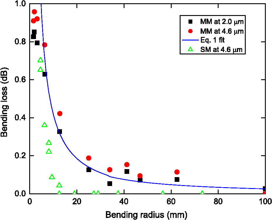 The solid line in Fig. 3 shows the expected bending loss for a fiber with the same parameters as the one used in the experiment according to the theoretical description of Gloge.17 The model describes the power loss for a mode propagating at an angle to the axis of a step index fiber as where is the refractive index of the core, is the propagation constant, is the free-space wavelength of the light, is the critical angle for propagation, is the radius of the fiber, and R is the bending radius. To determine the accurate fit of the bending loss, we have followed a similar procedure as described in Ref. 1. The numerical aperture of the fiber is measured, providing the angular power distribution of the fiber. The measured numerical aperture of the multimode fiber was fitted to Supergaussian function ; with , . The exponential loss induced by the bend according to Eq. (1) is calculated at each angle, and the transmitted power is determined with respect to the total input power.1The bending loss measurements at bending radii were masked by the physical rigidity of the fiber. As can be seen in Fig. 4, when the mandrel dimensions became too small, the fiber failed to conform to the mandrel. The plot points for sub 5-mm radius in Fig. 3 indicate the mandrel size is not the actual bend of the fiber, explaining the divergence between the theoretical loss and the measured loss for bending radii. We observed that increasing the tension to ensure that the fiber would conform to the mandrel at these dimensions caused the fiber to break. This is consistent with the fiber bending strength expected from the fiber’s Young’s modulus. From the known fiber modulus,9 we can estimate the minimum radius at which the fiber will fail under tension to be somewhere between 2 and 3.5 mm.18 The power handling of a tightly coiled fiber was also performed. These experiments were performed to simulate a realistic case scenario of high power handling of the fiber when coupled from a stand-alone laser. The laser emission of a 2-μm Thulium fiber laser was focused with a 40-mm focusing length lens, leading to a 70-μm focal diameter spot at the fiber input face. The laser was not modulated. Figure 5 shows the results at the smallest bend radius tested (6.25 mm). The maximum incident power on the front face of the fiber was 8.3 W, with present immediately before the bend (calculated from the measured output power taking into account the end face reflection loss and transmission loss). A minimum bend radius of 6.25 mm was tested with no damage or transmission drop observed, even after 20 min of continuous monitoring. Fig. 5Output power after propagating through a 180 deg bend with 6.25-mm bending radius versus incident power at 2-μm wavelength. The output power has been corrected to account for the end face reflection. The horizontal error bars at the highest incident power show the variation in power over a period of 20 min. The variation is smaller than the laser power variation of 5%.  4.SummaryWe present results for the bending loss for a multimode chalcogenide fiber over a wide range of infrared wavelengths and a single-mode fiber excited by a 4.6-μm laser. The increase in loss due to tight bends remains below 1 dB even for sub 10-mm bend radii. For packing applications, if the loss of 1 dB is tolerable, the main constrain will be the fiber’s critical mechanical limit, which occurs around 3.5-mm bending radius. ReferencesA. A. P. Boechatet al.,
“Bend loss in large core multimode optical fiber beam delivery systems,”
Appl. Opt., 30
(3), 321
–327
(1991). http://dx.doi.org/10.1364/AO.30.000321 APOPAI 0003-6935 Google Scholar
J. A. Harrington, Infrared Fibers and Their Applications, SPIE, Washington
(2004). Google Scholar
L. E. BusseI. D. Aggarwal,
“Design parameters for fluoride multimode fibers,”
J. Lightw. Technol., 9
(7), 828
–831
(1991). http://dx.doi.org/10.1109/50.85781 JLTEDG 0733-8724 Google Scholar
D. G. KotsifakiA. A. Serafetinides,
“Mid-infrared radiation transmission through fluoride glass multimode optical fibers,”
Opt. Laser Technol., 43
(8), 1448
–1452
(2011). http://dx.doi.org/10.1016/j.optlastec.2011.04.017 OLTCAS 0030-3992 Google Scholar
J. Harrington,
“A review of IR transmitting, hollow waveguides,”
Fiber Integr. Opt., 19
(3), 211
–227
(2000). http://dx.doi.org/10.1080/01468030050058794 Google Scholar
A. Urich,
“Flexible delivery of Er:YAG radiation at 2.94 μm with negative curvaturesilica glass fibers: a new solution for minimally invasive surgical procedures,”
Biomed. Opt. Express, 4
(2), 193
–205
(2013). http://dx.doi.org/10.1364/BOE.4.000193 BOEICL 2156-7085 Google Scholar
S. Satoet al.,
“Multihundred-watt CO laser power delivery through chalcogenide glass fibers,”
Appl. Phys. Lett., 62
(7), 669
–671
(1993). http://dx.doi.org/10.1063/1.108834 APPLAB 0003-6951 Google Scholar
J. Nishiiet al.,
“Recent advances and trends in chalcogenide glass fiber technology: a review,”
J. Non-Cryst. Solids, 140
(0), 199
–208
(1992). http://dx.doi.org/10.1016/S0022-3093(05)80767-7 JNCSBJ 0022-3093 Google Scholar
J. S. SangheraI. D. Aggarwal,
“Active and passive chalcogenide glass optical fibers for IR applications: a review,”
J. Non-Cryst. Solids, 256–257
(0), 6
–16
(1999). http://dx.doi.org/10.1016/S0022-3093(99)00484-6 JNCSBJ 0022-3093 Google Scholar
L. E. Busseet al.,
“Multi-kilowatt peak power transmission through infrared fibers in the 3–5 μm region,”
in Proc 36th IRIS Symp. Infrared Countermeas.,
123
(1998). Google Scholar
J. Sangheraet al.,
“Reduced Fresnel losses in chalcogenide fibers by using anti-reflective surface structures on fiber end faces,”
Opt. Express, 18
(25), 26760
–26768
(2010). http://dx.doi.org/10.1364/OE.18.026760 OPEXFF 1094-4087 Google Scholar
N. Granzowet al.,
“Supercontinuum generation in chalcogenide-silica step-index fibers,”
Opt. Express, 19
(21), 21003
–21010
(2011). http://dx.doi.org/10.1364/OE.19.021003 OPEXFF 1094-4087 Google Scholar
A. Tunizet al.,
“Two-photon absorption effects on Raman gain in single mode As_2Se_3 chalcogenide glass fiber,”
Opt. Express, 16
(22), 18524
(2008). http://dx.doi.org/10.1364/OE.16.018524 OPEXFF 1094-4087 Google Scholar
J. Troleset al.,
“Low loss microstructured chalcogenide fibers for large non linear effects at 1995 nm,”
Opt. Express, 18
(25), 26647
–26654
(2010). http://dx.doi.org/10.1364/OE.18.026647 OPEXFF 1094-4087 Google Scholar
V. Q. Nguyenet al.,
“Fabrication of Arsenic Sulfide Optical Fiber with Low Hydrogen Impurities,”
J. Am. Ceram. Soc., 85
(8), 2056
–2058
(2002). http://dx.doi.org/10.1111/jace.2002.85.issue-8 JACTAW 0002-7820 Google Scholar
G. E. Snopatinet al.,
“High-purity chalcogenide glasses for fiber optics,”
Inorg. Mater., 45
(13), 1439
–1460
(2009). http://dx.doi.org/10.1134/S0020168509130019 INOMAF 0020-1685 Google Scholar
D. Gloge,
“Bending loss in multimode fibers with graded and ungraded core index,”
Appl. Opt., 11
(11), 2506
–2513
(1972). http://dx.doi.org/10.1364/AO.11.002506 APOPAI 0003-6935 Google Scholar
M. J. MatthewsonC. R. KurkjianS. T. Gulati,
“Strength Measurement of Optical Fibers by Bending,”
J. Am. Ceram. Soc., 69
(11), 815
–821
(1986). http://dx.doi.org/10.1111/jace.1986.69.issue-11 JACTAW 0002-7820 Google Scholar
|


