|
|
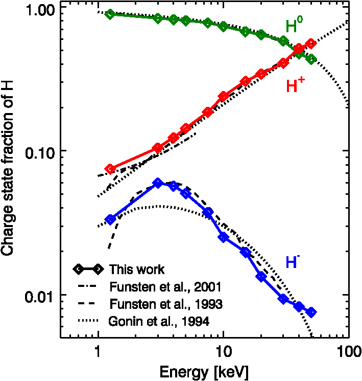
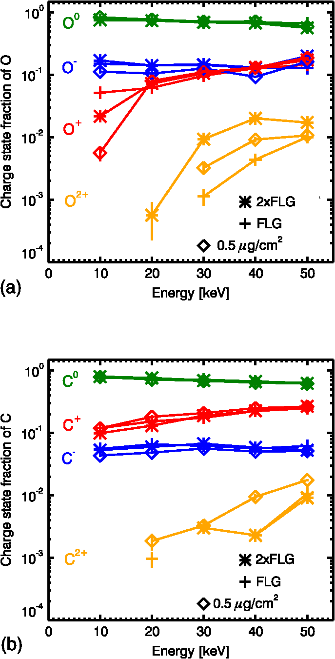
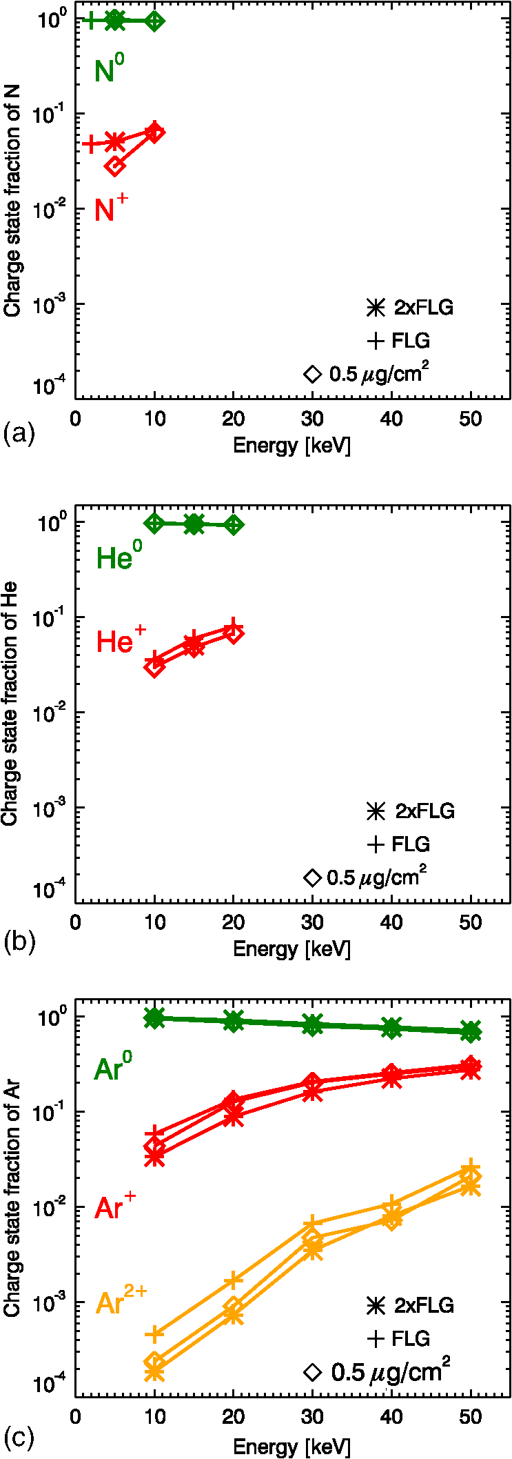
1.IntroductionCarbon foils are used in space plasma instrumentation to enable the detection of ions and neutral atoms.1 These particles create secondary electron emission when passing through the foils.2,3 The secondary electrons are detected by electron multipliers—typically channel electron multipliers4 or microchannel plates (MCPs)5—to create a coincidence and/or a timing signal. Another result of this interaction is charge exchange, in which the projectile gains and loses electrons predominantly by interactions with the band structure of the foil. The exit charge state distribution mainly depends on the velocity and the atomic number of the particle. At keV energies, the incident charge state—the charge that a particle has before interacting with the foil—does not affect the exit charge state—the charge that a particle has after leaving the foil. Under these circumstances, the particle velocity is lower or comparable to the Bohr velocity () so that foil conduction electrons are sufficiently mobile over the interaction time scales to freely interact with the projectile. Therefore, charge equilibrium of the particle is reached in the first few atomic layers of the foil and the charge state memory of the incident particle is lost. The property of charge conversion with foils is used, for example, in different space plasma instruments—for solar wind, magnetospheric, and heliospheric missions—and as charge strippers in high-energy particle accelerators. Here, we focus only on space plasma instrumentation for ions (and neutral atoms) in the range from to 50 keV. It is important to know the charge distribution upon exit from the foil. For example, the mass time-of-flight sensor part of the charge, element, and isotope analysis system (CELIAS) experiment6 on solar and heliospheric observatory (SoHO) has an isochronous time-of-flight section that uses a carbon foil. The ions of same mass-per-charge have an identical time-of-flight between the carbon foil and the detector. Therefore, it is imperative to know the exit charge state distribution of ions after the foil in order to calculate abundance ratios between species. Another example where the exit charge state distribution is critical is the cassini plasma spectrometer/ion mass spectrometer (CAPS/IMS) sensor7 on Cassini. The particles, depending on their charge state, land on different detectors in the time-of-flight section. The charge state distributions are used to determine accurate mass spectra. An extensive contribution to the literature on charge exchange at keV energies was done by the Space Research and Planetary Sciences Division at the University of Bern.8–14 They measured the charge state distributions after carbon foils of the major solar wind ions and proposed a mechanism to explain the charge exchange properties, which led to a semiempirical model. Other groups—e.g., the Space Plasma Physics Group at the Los Alamos National Laboratory15–20—also contributed significantly to the topic, especially for ultrathin ( or atoms thick) carbon foils. The property of charge exchange is also critical to the detection of energetic neutral atoms (ENA). ENA imaging has become an important element of heliospheric research with the recent interstellar boundary explorer (IBEX)21 which has solidified this imaging technique as a critical component of future NASA heliospheric and magnetospheric missions. Neutral atom imagers, such as those on IBEX, cover energies from 0.01 to 100 keV, encompassing the entire energy range of neutral atoms (and their parent ion populations) in the magnetosphere, heliosphere, and interstellar medium. To measure neutrals over this broad energy range, different types of imagers are required. Most imagers have a key subsystem that converts an incoming neutral atom into an ion. Then, the ion can be deflected away from the initial neutral direction. This deflection is critical for separating the original signal from much higher backgrounds (e.g., ultraviolet radiation) that are present in space. The conversion subsystem is the least efficient subsystem in a neutral atom imager, especially at energies below 1 keV. The state-of-the-art neutral atom camera IBEX-Hi22 demonstrates this point. This system uses an ultrathin carbon foil1,23 to convert an incident neutral atom into a positive ion. The foil has a thickness of the order of atoms, allowing transmission down to energies of several hundreds of eV. However, the probability of producing a charged particle decreases dramatically for neutral atom energies below 1 keV. Furthermore, the probability of transmission through the foil also decreases dramatically below about 0.5 keV [e.g., at 0.2 keV (Ref. 20)], resulting in very low overall efficiencies at energies of a few hundreds of eV. Graphene, being the strongest material known on Earth,24 can be made much thinner (as low as 1 atomic layer) than the regular amorphous carbon ( atoms thick). Therefore, to first-order, particles passing through few layer graphene (FLG) foils should 1. lose less energy, 2. scatter less, and 3. be transmitted at lower energies than through amorphous carbon foils. The motivation for using graphene foils is obvious: these foils could potentially reduce angular scattering and energy straggling—two effects that can degrade the performance of an instrument. For ENA imaging, a critical parameter is the charge conversion efficiency of a neutral atom into an ion. Is the charge conversion efficiency of graphene comparable to that of amorphous carbon? The intrinsic differences between the graphene and amorphous carbon should yield different exit charge state distributions. However, the adsorbates—associated with vacuum—are likely to be similar and drive the exit charge state distributions toward similar values. In this study, we present measurements of exit charge state distributions of to 50 keV ions passing through graphene foils for the first time, and compare them with measurements using state-of-the-art amorphous carbon foils (). A parallel study by Ebert et al.25 presents measurements of ion scattering by the same graphene foils and a comparison with state-of-the-art carbon foils (). In a future study, we plan to characterize the energy straggling and the transmission as a function of energy of ions passing through amorphous carbon and graphene foils. 2.SetupOur setup design is similar to that of previous works.9,15 The principle is illustrated in Fig. 1(a). A collimated beam of positive ions passes through the foils and scatters. Further downstream, a slit collimates scattered ions in a fan-like shape. Then, deflection plates parallel to the slit separate ions according to their charge. The neutrals go straight through, and positive and negative ions are deflected away from the neutrals in opposite directions. A position sensitive detector measures the particles. Since neutrals and ions of different charges follow different trajectories, they land on the detector at different locations. An image of the impact location shows different bands corresponding to the respective charge states [cf. Fig. 1(b)]. Charge state distributions are readily inferred from the number of counts in each band. Fig. 1(a) Exit charge state distribution setup cross section showing the different paths of charged and neutral particles after the foil. (b) Example of an image obtained on the position sensitive detector and its projection onto the vertical axis.  Our imaging detector is a Quantar detector with MCPs in chevron configuration. The active area of the resistive anode is about . We bias the front MCPs at (to avoid contamination with secondary electrons from the foil) and the resistive anode is at . All measurements are taken at a pressure of to . It is possible that the foils have pinholes26 that would let ions pass through without interaction. These ions will show up in the band of positive ions. The pinholes are relatively easy to identify with slow heavy ions27 because the ions that interact with the foil strongly scatter whereas those that pass through the pinholes do not. The ions passing through pinholes in the foil land in a small area on the detector. If pinholes are identified, then we can disregard this small area and use counts from neighboring pixels to interpolate the counts of scattered ions in this area. To mitigate potential systematic differences between the measurements of the positive and negative charge state fractions, we swap polarities of the deflection plates [cf. Fig. 1(a)] and take a second measurement. We calculate the average charge state fraction from both measurements. Note that the difference between the two measurements is usually comparable to the statistical uncertainty of the measurements. Figure 2 shows the charge state fraction of hydrogen after passing through a regular amorphous carbon foil of nominal thickness . This amorphous carbon foil was purchased from Arizona Carbon Foil Co., Inc, Tucson, Arizona. We compare our results to three previous studies. The curves from Funsten et al.15,20 are fits through their measurements taken with similar carbon foils. The curves from Gonin et al.26 are from a semiempirical model. The main difference is that the latter study gives charge states as a function of residual energy—the energy of the ions leaving the exit surface after suffering energy loss inside the foil. Although the relative difference between incident and residual energy is small at the higher end of this energy range, it is more significant at the lower end. We do not measure the energy loss with our setup and, thus, we cannot convert the horizontal scale to residual energy at this point. Nevertheless, our results agree very well with the previous published work and that validates our setup and procedure. 3.Charge States at Exit of Graphene FoilsWe affixed an FLG ( to 7) foils on nickel grids (333 and 1000 lpi). The thickness is determined by Raman spectroscopy using the shape of the two-dimensional peak and by optical transmission. The thickness of the foil ranges from to . The few layers of graphene are created on copper sheets that are subsequently etched in an acid bath. Once the copper is completely etched away, the bath is neutralized and the graphene foil floating process can take place. The graphene foil is picked up by the grids and removed from the bath. After it is dry, the graphene foil is ready for testing. We also floated two FLG foils (hereafter, abbreviated as 2xFLG) onto the same substrates in order to improve the quality of the foils and reduce pinholes. The second foil was floated on the top of the first one after it dried. Since (a) the foils are easy to see with the naked eye and (b) we saw that the first foil remained attached during the second floating, we assume that the two foils were successfully stacked together. These foils are still much thinner () than a nominal amorphous carbon foil. Figure 3(a) shows the fraction of neutral, positive, and negative hydrogen exiting graphene and amorphous carbon foils as a function of incident energy. Figure 3(b) shows the same data on expanded scales. The charge state distribution after passing through graphene is roughly similar to that of amorphous carbon. There are absolute differences of up to (at 15 and 30 keV) for positive ions and neutral atoms between the graphene and amorphous carbon foils. The maximum absolute difference for negative ions is . Graphene (FLG and 2xFLG) appears to produce more positive ions than the amorphous carbon at low energies [see Fig. 3(b)]. Fig. 3(a) Charge state fractions of hydrogen after passing through an ultrathin (nominal thickness of ) amorphous carbon foil, a single (FLG) graphene foil, and a double (2xFLG) graphene foil. (b) Same data zoomed in. The uncertainties (smaller than the symbols) are derived from propagation of the Poisson errors for the individual measurements. 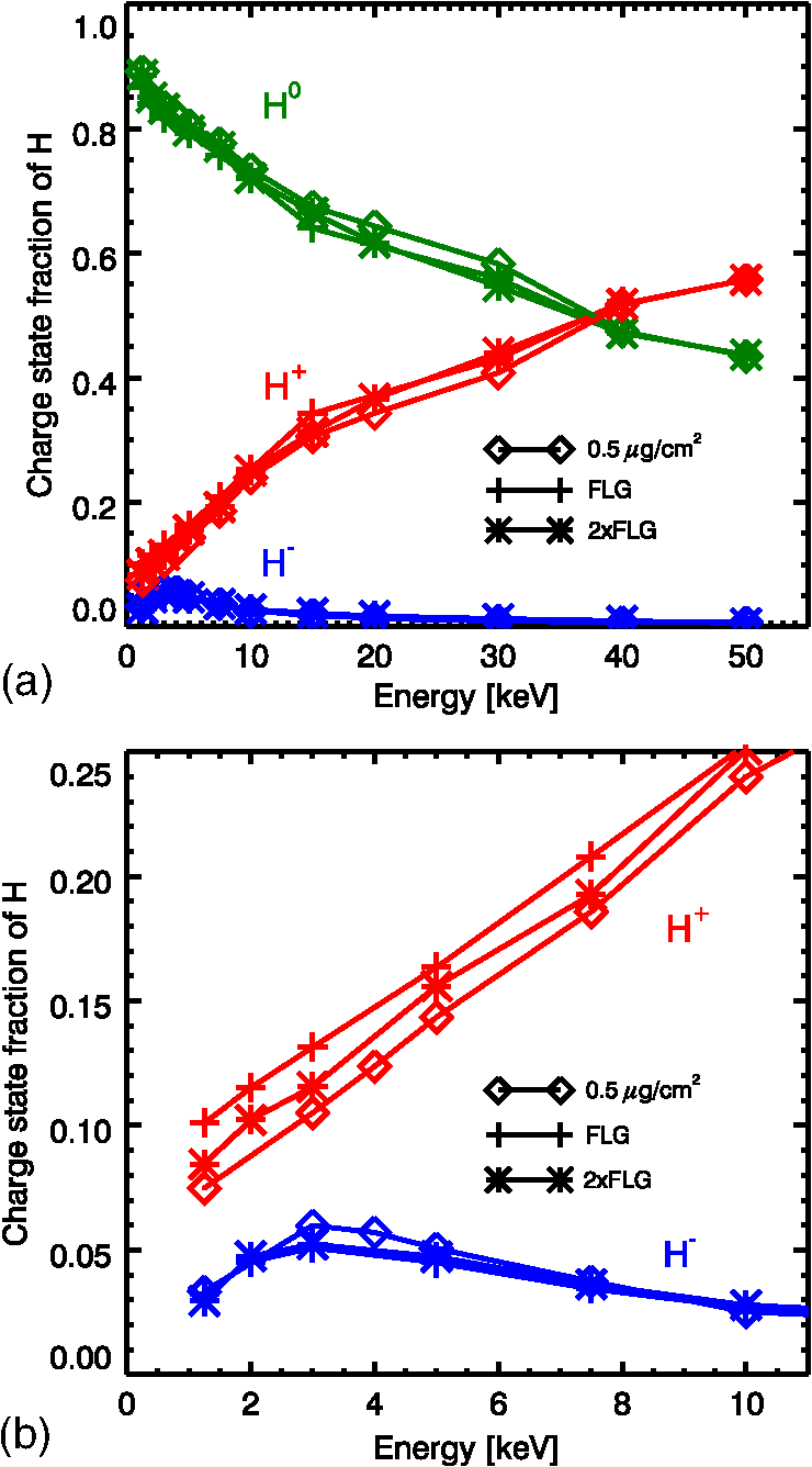 Figure 4(a) shows the fraction of the different charge states of oxygen after the graphene and amorphous carbon foils. Here again, there are only very small differences between these foils. The largest differences are at the lowest energies or for the minor charge states such as and . Graphene produces more negative ions than the amorphous carbon up to . Figure 4(b) shows the fraction of the different charge states of carbon after passing through the same foils. Similarly to hydrogen and oxygen, there is not much difference between the graphene and amorphous carbon foils. Figure 5 shows the fraction of the different charge states of nitrogen, helium, and argon after passing through graphene and amorphous carbon. There are only very small differences between the two foil types. For argon, there is no systematic difference. 4.DiscussionWe measured the charge state fractions of ions after passing through graphene and amorphous carbon foils. The measurements cover an energy range of to 50 keV. We find that:
The charge state of a particle exiting a foil in our energy range is determined mainly by the three factors: 1. the particle atomic number, 2. the foil surface composition, and 3. the particle velocity when it leaves the surface. In our experiment, it is reasonable to assume that the particle velocity is roughly equal for graphene and amorphous carbon even though graphene is supposed to be much thinner. This argument is supported by our data in the sense that there is no systematic difference that applies to all species. Even if this assumption was not true, the difference would be small because the total energy loss is a small fraction (a few to ) of the total energy. The fact that both graphene and amorphous carbon foils yield similar exit charge state distributions suggests that the common adsorbates material is perhaps the governing driver for the exit charge state distribution. It is well known that amorphous carbon foils have layers of impurities28,29 on their surface that can account for a significant fraction of the total foil thickness.23,30 Thus, it is likely that the graphene foils have similar impurities sticking to their surface. The chemistry might be different, but graphene, similarly to graphite, adsorbs, and desorbs various molecules. Measurements of angular scattering distributions with graphene foils by Ebert et al.25 support the hypothesis of the impurities on the surface of the foil. We mentioned in Sec. 1 a future study to measure the energy straggling and the transmission as a function of energy of ions passing through amorphous carbon and graphene foils. The measurements presented here, the energy straggling, and the angular scattering measurements can provide important clues to determine whether graphene foils also have layers of impurities. This study shows that graphene performs similarly to amorphous carbon when it comes to converting ENA into ions. Thus, it is conceivable that graphene foils could replace amorphous carbon foils in ENA detectors in the future, provided that they present an advantage for other properties such as angular scattering and energy loss. AcknowledgmentsThe authors would like to acknowledge the contributions from Jessica Armstrong, Dave Cronk, Guy Grubbs, Dave McComas, Greg Miller, Ed Patrick, Steve Petrinec, Amanda Richter, Ben Rodriguez, Ken Smith, and Phil Valek. This research was funded by an internal research and development grant at Southwest Research Institute and internal research funding at Lockheed Martin Space Systems Company, Advanced Technology Center. ReferencesD. J. McComaset al.,
“Ultra-thin () carbon foils in space instrumentation,”
Rev. Sci. Instrum., 75
(11), 4863
–4870
(2004). http://dx.doi.org/10.1063/1.1809265 RSINAK 0034-6748 Google Scholar
S. M. RitzauR. A. Baragiola,
“Electron emission from carbon foils induced by keV ions,”
Phys. Rev. B, 58
(5), 2529
–2538
(1998). http://dx.doi.org/10.1103/PhysRevB.58.2529 PRBMDO 1098-0121 Google Scholar
F. Allegriniet al.,
“Determination of low-energy ion-induced electron yields from thin carbon foils,”
Nucl. Instrum. Methods B, 211
(4), 487
–494
(2003). http://dx.doi.org/10.1016/S0168-583X(03)01705-1 NIMBEU 0168-583X Google Scholar
E. A. Kurz,
“Channel electron multipliers,”
American Laboratory, International Scientific Communications, Fairfield, Connecticut(1979). Google Scholar
J. L. Wiza,
“Microchannel plate detectors,”
Nucl. Instrum. Methods A, 162
(1–3), 587
–601
(1979). http://dx.doi.org/10.1016/0029-554X(79)90734-1 NUIMAL 0029-554X Google Scholar
D. Hovestadtet al.,
“CELIAS–charge, element and isotope analysis system for SOHO,”
Solar Phys., 162
(1–2), 441
–481
(1995). http://dx.doi.org/10.1007/BF00733436 SLPHAX 0038-0938 Google Scholar
D. T. Younget al.,
“Cassini plasma spectrometer investigation,”
Space Sci. Rev., 114
(1–4), 1
–112
(2004). http://dx.doi.org/10.1007/s11214-004-1406-4 SPSRA4 0038-6308 Google Scholar
A. Bürgiet al.,
“Charge exchange of low-energy ions in thin carbon foils,”
J. Appl. Phys., 68
(6), 2547
–2554
(1990). http://dx.doi.org/10.1063/1.346478 JAPIAU 0021-8979 Google Scholar
A. Bürgiet al.,
“Charge exchange of low energy ions in thin carbon foils. II. Results for ions of B, C, F, Ne, Na, Si, S, Cl, Ar, K, and Fe,”
J. Appl. Phys., 73
(9), 4130
–4139
(1993). http://dx.doi.org/10.1063/1.352846 JAPIAU 0021-8979 Google Scholar
M. GoninR. KallenbachP. Bochsler,
“Charge exchange of hydrogen atoms in carbon foils at 0.4–120 keV,”
Rev. Sci. Instrum., 65
(3), 648
–652
(1994). http://dx.doi.org/10.1063/1.1145132 RSINAK 0034-6748 Google Scholar
M. GoninR. KallenbachP. Bochsler,
“Charge exchange of atoms with high first ionization potentials in carbon foils at E ,”
Nucl. Instrum. Methods B, 94
(1–2), 15
–21
(1994). http://dx.doi.org/10.1016/0168-583X(94)95652-9 NIMBEU 0168-583X Google Scholar
M. Goninet al.,
“Charge exchange of low energy particles passing through thin carbon foils: dependence on foil thickness and charge state yields of Mg, Ca, Ti, Cr and Ni,”
Nucl. Instrum. Methods B, 101
(4), 313
–320
(1995). http://dx.doi.org/10.1016/0168-583X(95)00559-5 NIMBEU 0168-583X Google Scholar
R. Kallenbachet al.,
“Charge exchange of hydrogen ions in carbon foils,”
Nucl. Instrum. Methods B, 83
(1–2), 68
–72
(1993). http://dx.doi.org/10.1016/0168-583X(93)95909-O NIMBEU 0168-583X Google Scholar
R. Kallenbachet al.,
“Charge exchange of B, C, O, Al, Si, S, F and Cl passing through thin carbon foils at low energies: formation of negative ions,”
Nucl. Instrum. Methods B, 103
(2), 111
–116
(1995). http://dx.doi.org/10.1016/0168-583X(95)00646-X NIMBEU 0168-583X Google Scholar
H. O. FunstenD. J. McComasB. L. Barraclough,
“Ultrathin foils used for low-energy neutral atom imaging of the terrestrial magnetosphere,”
Opt. Eng., 32
(12), 3090
–3095
(1993). http://dx.doi.org/10.1117/12.149187 OPEGAR 0091-3286 Google Scholar
H. O. FunstenB. L. BarracloughD. J. McComas,
“Shell effects observed in exit charge state distribution of 1–30 keV atomic projectiles transiting ultrathin carbon foils,”
Nucl. Instrum. Methods B, 80 49
–52
(1993). http://dx.doi.org/10.1016/0168-583X(93)96074-M NIMBEU 0168-583X Google Scholar
H. O. FunstenB. L. BarracloughD. J. McComas,
“Interactions of slow H, H2, and H3 with thin carbon foils,”
Nucl. Instrum. Methods B, 90
(1–4), 24
–28
(1994). http://dx.doi.org/10.1016/0168-583X(94)95503-4 NIMBEU 0168-583X Google Scholar
H. O. Funsten,
“Formation and survival of H– and C– ions transiting ultrathin carbon foils at keV energies,”
Phys. Rev. B, 52
(12), 8703
–8706
(1995). http://dx.doi.org/10.1103/PhysRevB.52.R8703 PRBMDO 1098-0121 Google Scholar
H. O. FunstenS. M. RitzauR. W. Harper,
“Negative helium ions exiting a carbon foil at keV energies,”
Phys. Rev. B, 63
(15), 155416
(2001). http://dx.doi.org/10.1103/PhysRevB.63.155416 PRBMDO 1098-0121 Google Scholar
H. O. FunstenD. J. McComasM. Gruntman,
“Energetic neutral atom imaging of the outer heliosphere-LISM interaction region,”
The Outer Heliosphere: The Next Frontiers, 237 Pergamon, Amsterdam(2001). Google Scholar
D. J. McComaset al.,
“IBEX—interstellar boundary explorer,”
Space Sci. Rev., 146
(1–4), 11
–33
(2009). http://dx.doi.org/10.1007/s11214-009-9499-4 SPSRA4 0038-6308 Google Scholar
H. O. Funstenet al.,
“The interstellar boundary explorer high energy (IBEX-Hi) neutral atom imager,”
Space Sci. Rev., 146
(1–4), 75
–103
(2009). http://dx.doi.org/10.1007/s11214-009-9504-y SPSRA4 0038-6308 Google Scholar
F. Allegriniet al.,
“Energy loss of 1–50 keV H, He, C, N, O, Ne, Ar ions transmitted through thin carbon foils,”
Rev. Sci. Instrum., 77
(4), 044501
(2006). http://dx.doi.org/10.1063/1.2185490 RSINAK 0034-6748 Google Scholar
C. Leeet al.,
“Measurement of the elastic properties and intrinsic strength of monolayer graphene,”
Science, 321
(5887), 385
–388
(2008). http://dx.doi.org/10.1126/science.1157996 SCIEAS 0036-8075 Google Scholar
R. W. Ebertet al.,
“Angular scattering of 1–50 keV ions through graphene and thin carbon foils: potential applications for time-of-flight ion mass spectrometers and energetic neutral atom sensors in space,”
(2014). Google Scholar
H. O. FunstenB. L. BarracloughD. J. McComas,
“Pinhole detection in thin foils used in space plasma diagnostic instrumentation,”
Rev. Sci. Instrum., 63
(10), 4741
–4743
(1992). http://dx.doi.org/10.1063/1.1143626 RSINAK 0034-6748 Google Scholar
H. O. FunstenD. J. McComasB. L. Barraclough,
“Thickness uniformity and pinhole density analysis of thin carbon foils using incident keV ions,”
Nucl. Instrum. Methods B, 66
(4), 470
–478
(1992). http://dx.doi.org/10.1016/0168-583X(92)95421-M NIMBEU 0168-583X Google Scholar
D. BalzerG. Bonani,
“Impurities in carbon foils,”
Nucl. Instrum. Methods A, 167
(1), 129
–133
(1979). http://dx.doi.org/10.1016/0029-554X(79)90491-9 NUIMAL 0029-554X Google Scholar
M. A. Gruntman,
“MASTIF: mass analysis of secondaries by time-of-flight technique. A new approach to secondary ion mass spectrometry,”
Rev. Sci. Instrum., 60
(10), 3188
–3194
(1989). http://dx.doi.org/10.1063/1.1140550 RSINAK 0034-6748 Google Scholar
G. Bothet al.,
“Ultrathin foils for Coulomb explosion experiments,”
Rev. Sci. Instrum., 58
(3), 424
–427
(1987). http://dx.doi.org/10.1063/1.1139248 RSINAK 0034-6748 Google Scholar
BiographyFrédéric Allegrini is a principal scientist at the Southwest Research Institute. He received a MS in physics from the University of Lausanne and a PhD in space physics from the University of Berne. His primary interests are space plasma instrumentation, carbon foils for space applications, and data analysis in the area of heliospheric physics. He joined the Department of Physics and Astronomy at UTSA as an adjoint assistant professor. Robert W. Ebert is a research scientist at the Southwest Research Institute. He has earned degrees from the University of Calgary (BS in astrophysics), the University of Toronto (MS in engineering physics), and the University of Texas at San Antonio (PhD in space physics). His research interests include the solar wind and its interaction with Jupiter’s magnetosphere, the origin, acceleration, and transport of energetic particles in interplanetary space, and developing new technologies for space science instrumentation. Stephen A. Fuselier is the director for Space Science, Space Science and Engineering Division, Southwest Research Institute. He has more than 25 years of experience as a scientist, project manager, and senior manager for scientists, engineers, and technicians. He is a co-investigator and sensor lead on the Interstellar Boundary Explorer (IBEX) mission, co-investigator and lead for the Hot Plasma Composition Experiment (HPCA) on the Magnetospheric Multiscale, and co-investigator on IMAGE, and ROSINA. Georgios Nicolaou is a PhD candidate in University of Texas at San Antonio (UTSA) and he is working as research assistant at Southwest Research Institute. He received MS in physics from the National and Kapodistrian University of Athens. His main interests are data analysis in the area of planetary and heliospheric physics, thermodynamics of space plasma and carbon foils for space instrumentation applications. Peter Bedworth is a senior staff chemist at Lockheed Martin Space Systems Advanced Technology Center. He received his BS (Chemistry) from Augusta College, his PhD (Chemistry) from University of South Carolina under James Tour and was a research fellow at Caltech with Seth Marder. He has co-authored numerous patents and publications. His primary research thrust is the synthesis and characterization of 2D and structured materials for optical, electronic, magnetic and membrane devices. Steve Sinton is a Lockheed Martin Fellow at the Advanced Technology Center of LM Space Systems Company. He received a PhD in physical Chemistry from the University of California, Berkeley. His primary interests are materials science and nanotechnology in aerospace and commercial applications. Karlheinz J. Trattner received a BSc in physics from the University of Graz, Austria, in 1983; a MSc in geophysics from the University of Graz, Austria, in 1989; and a PhD in space science from the University of Graz, Austria in 1992. He has held a post at Lockheed Martin ATC in Palo Alto California for 16 year and worked as a Science Lead on several investigations about solar-terrestrial interactions and magnetic reconnection. |