
|
|
1.IntroductionA number of applications of ultrashort laser pulses in medicine, industry, and defense require high average power and high pulse energy. However, direct amplification of ultrashort pulses can induce detrimental nonlinear effects and/or laser-induced damage in amplifiers due to the extremely high peak power of the amplified pulses. A technique called chirped pulse amplification (CPA) was proposed in Ref. 1 to mitigate these effects. In this technique, low-power ultrashort pulses are stretched (“chirped”) in time and space using dispersive optical elements. Stretched pulses having lower power density are then amplified to a power level somewhat less than the damage threshold of the amplifying system. The amplified chirped pulses are compressed by the same or similar dispersive optical elements that were used for stretching. The highest peak power that can be obtained using this technique is determined primarily by the optical damage threshold of the compressor components. Initially, pulse stretching and compression in CPA systems were performed almost exclusively by pairs of surface diffraction gratings2,3 that usually are called “Treacy stretchers and compressors.” Although the conventional technology that uses surface diffraction gratings provides a dramatic increase in the achievable power level, it has limitations associated with the reduced average power handling capacity of these components, which is typically in the range of tens of watts. With the availability today of fiber lasers operating at power levels easily exceeding 1 kW, this limitation has become the main obstacle to power scaling of ultrashort pulse lasers. Additionally, Treacy stretchers and compressors require highly uniform, large aperture gratings and large grating separation distances. Such stretchers and compressors are bulky, difficult to align, and susceptible to vibrations. An important advancement in the development of CPA systems was made by the use of fiber-chirped Bragg gratings (CBGs).4,5 This approach has dramatically increased the robustness of CPA systems enabling their use in harsh environments outside of research laboratories. However, while fiber stretching became the conventional method for CPA systems design, the limited aperture of chirped fiber Bragg gratings imposes limitations on the peak power achievable with fiber-based pulse compressors due to nonlinear effects in the fibers and laser-induced damage of the fibers. To overcome these limitations, the use of volume CBGs for pulse stretching and compression has been proposed.6 Initially, implementation of this proposal was slow to develop because of the absence of a suitable technology for fabrication of such optical elements. All of the photosensitive materials that were available at that time for volume hologram recording could not satisfy the requirements for high power applications in laser systems.7 The situation changed when the bulk holographic material—photo-thermo-refractive (PTR) glass8,9—was developed10 which further enabled the development of the technology of high efficiency volume Bragg gratings. The creation of volume CBGs (volume Bragg gratings) with a variable period in the direction of the beam propagation) recorded in PTR glass enabled a new approach to the design of high power stretchers and compressors, and has become an important, competing CPA technique.11–13 A conventional compressor is based on a pair of surface diffraction gratings that must be placed at some distance from each other, and occupies a volume of several liters, not including the size of large aperture telescopes, mirrors, etc. A typical CBG enables decreasing the size and weight of compressors by several orders of magnitude—to 0.005 L, for example. The most vulnerable feature of Treacy compressors is their high sensitivity to vibrations and shocks that result in misalignment between the diffraction gratings. The use of CBG stretchers and compressors enhances the robustness of CPA systems because these devices are monolithic, meaning there is nothing within the stretcher/compressor function to become misaligned (although it still must be aligned with the input beam). Thus, these devices are inherently free from the effects of vibration and shocks. The main limitation of CBG stretchers and compressors at the current level of the technology of volume Bragg gratings recorded in PTR glass is a narrow spectral width that restricts operations to pulses longer than 100 fs. 2.Stretching and Compression of Laser Pulses by Volume CBGsA uniform volume Bragg grating is a phase volume hologram produced by recording the interference pattern of two collimated beams [Fig. 1(a)]. This recording results in a spatial refractive index modulation (the creation of numerous planar layers having a modified refractive index) in the volume of the photosensitive optical material. These layers provide a resonant diffraction of optical beams that is described in Ref. 14 and detailed for engineering calculations in Refs. 15 and 16. The diffraction of radiation inside of this grating occurs if the Bragg conditions are satisfied where is the angle inside the photosensitive medium between a plane of constant refractive index and the direction of beam propagation, is the wavelength, is the average refractive index, and is the grating period. If a volume grating is positioned in such a manner that the diffracted beam [ in Fig. 2(a)] is deflected and crosses its back surface, this is defined as a transmitting Bragg grating. The beams that do not satisfy the Bragg conditions (either angle of incidence or wavelength or both) pass through the grating without changing their direction of propagation. If a volume grating is positioned in such a manner that the diffracted beam [ in Fig. 2(b)] crosses the entrance surface, this is defined as a reflecting Bragg grating or a Bragg mirror. Bragg mirrors recorded in PTR glass with thicknesses from a fraction of a millimeter to several centimeters have spectral widths ranging from a few nanometers down to a few picometers. An example of a diffraction efficiency spectrum for a uniform reflecting grating is shown in Fig. 3 (curve 1). Like a transmitting grating, beams not meeting the Bragg conditions propagate through the reflecting grating without changing their direction of propagation.Fig. 1Recording geometry for uniform gratings by interference of collimated beams (a) and for chirped gratings by interference of a convergent and a divergent beams (b). Arrows show the direction of the recording beam propagation. is the axis collinear to the grating vector. 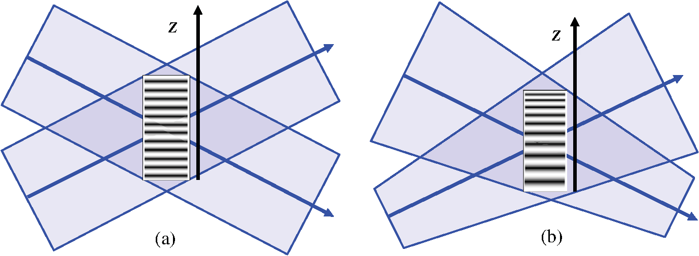 Fig. 2Schematics of beam diffraction by volume Bragg gratings. (a) Transmitting grating, (b) uniform reflecting grating (Bragg mirror), and (c) chirped reflecting grating, . Spatial modulation is not in scale—the typical period for a Bragg mirror at 1 μm is about 0.3 μm. 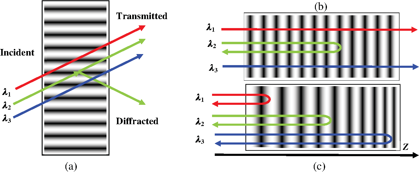 Fig. 3Modeled spectra of diffraction efficiency of lossless reflective gratings with different spectral chirp rates (SCRs). Parameters of modeling: central wavelength , spatial refractive index modulation , and thickness . SCR , : 1–0; 2–0.5; and 3–5, respectively. 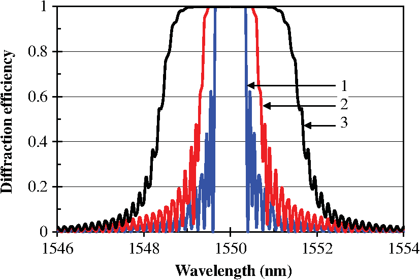 Although uniform volume gratings are recorded using an interference pattern produced by two collimated beams [Fig. 1(a)], it is possible to interfere a divergent beam with a convergent one [Fig. 1(b)]. In this case, the interference pattern consists of dark and bright planes with a period () gradually changing in the -direction perpendicular to a bisector of the recorded beams. If the convergence and divergence angles are equal, the resulting volume reflecting Bragg grating would have a period linearly varying in the -direction. If the period variation is directed along the beam propagation direction () of such an element, it is a longitudinal chirped reflecting volume Bragg grating depicted in Figs. 1(b) and 2(c). A detailed model of beam propagation in CBGs is described in Ref. 17. Thus, in this paper, we will use a simplified description for the specification of the basic parameters of CBGs. It is clear that a CBG can be considered as the sum of a great number of uniform gratings with different periods which provide an increased spectral width compared to that of a uniform grating. The reflection spectrum of a CBG depends on the chirp rate of the grating period, . For normal incidence, Eq. (1) gives a resonant wavelength . Therefore, a spectral chirp rate (SCR), which is the basic parameter of a CBG working close to the retroreflecting geometry, is determined as Such a grating can work as a wide band filter with a spectral width extending up to tens of nanometers depending on the SCR and the grating thickness as shown in Fig. 3 (curves 2 and 3). The total spectral width of a CBG is the product of the SCR and its thickness () The capability of CBGs for stretching pulses is illustrated in Fig. 2(c). One can see that different spectral components of a laser pulse would be reflected from different sections of the CBG. The total delay time (the maximum stretching) between spectral components corresponding to the front and back ends of a CBG with not very high diffraction efficiency 17 is determined by where is an average refractive index of the CBG and is the speed of light. This delay between spectral components of a laser pulse determines the ultimate time delay dispersion (TDD) or stretching factor (SF) of such a deviceThis parameter (TDD or SF) is in common use for CPA system design with dimensionality (). For a given SCR, a simple way to estimate SF for CBGs recorded in PTR glass with a refractive index close to is For an ideal CBG with a linear chirp, the delay of the different spectral components is a linear function of wavelength (a straight line in Fig. 4). In reality, the material dispersion of the photosensitive material, along with imperfections of a photosensitive material and within a hologram recording system, cause deviations from such a linear function. This distorted dispersion curve is often modeled by polynomial functions where the linear term is equal to the SF [Eq. (5)] and higher-order terms are called third-order dispersion (TOD), etc. Fig. 4Dependence of time delay on wavelength (time delay dispersion) of a 50-mm thick CBG centered at 1555 nm with a SCR of . Straight line—linear dispersion and squares—experimental data. 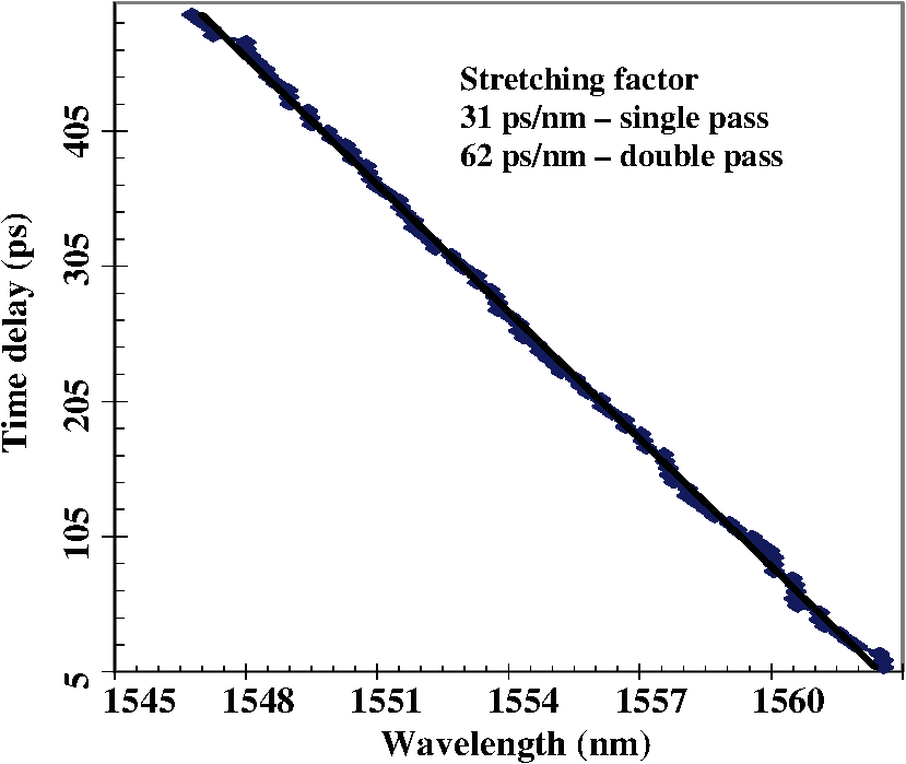 Recording of phase volume Bragg gratings in PTR glass is a result of the refractive index change caused by photoinduced precipitation of sodium fluoride nanocrystals.18 The refractive index modulation is proportional to the volume fraction of crystals precipitated in the volume of the PTR glass matrix.19 Although PTR glass is a highly transparent material, hologram recording causes some additional scattering and absorption.20 This induced absorption is caused by silver and silver halides in the short wavelength spectral region () and by a valence change of different impurities in the longer wavelength range.21 Induced scattering is the result of the precipitation of nanocrystals of sodium fluoride18 and it is proportional to the concentration of those crystals.22 The level of scattering in PTR glass containing a certain volume fraction of the crystalline phase is determined by the size of the crystals. The current technology results in a minimum size of crystals of about 15 nm; a further decrease of the crystal size would require the development of a new photosensitive material. The spectral dependence of the scattering coefficient (the internal optical density divided by the thickness in centimeters) produced by particles with sizes far below visible or IR wavelengths is described by the Rayleigh formula where is the scattering coefficient at . These losses are small in the near-IR spectral region—absorption is below , scattering is below and it dramatically decreases with the wavelength increasing in accordance with Eq. (7). However, the thickness of CBGs that provide stretching for several hundreds of picoseconds is several centimeters. For stretching followed by compression, each spectral component propagates through a doubled thickness of the CBG. This means that for 5-cm thick grating, the total attenuation in the vicinity of 1 μm could reach which would, therefore, significantly affect the properties of CBGs. For short wavelength compressors, the sharp dependence of scattering on wavelength results in high losses—losses exceeding 30% for 800 nm—yet results in almost lossless compressors in the vicinity of 2 μm. A decrease in the spectral width of CBGs (an increase in the SF) will allow decreasing the required refractive index modulation, and those gratings will have lower losses as will be shown in the next section.An experimental diffraction spectrum of a CBG centered at 1555 nm is shown in Fig. 5 (curve 1). One can see that the absolute diffraction efficiency (a combination of relative diffraction efficiencies and losses) at short wavelengths is lower than at longer wavelengths. It was confirmed that the relative diffraction efficiency, which is determined by the spatial refractive index modulation, is identical for all spectral components and the asymmetry in the diffraction spectrum is caused by losses. However, this asymmetry is not caused by the corresponding asymmetry of absorption or scattering spectra (which are flat in this narrow spectral region) but is a result of illuminating the CBG from the end with the larger grating period [from the left side in Fig. 2(c)] which is called the “red end”. In this case, the spectral components with shorter wavelengths propagate longer distances and accumulate higher losses. Illumination of the same CBG from the “blue end” results in higher losses and a lower absolute diffraction efficiency for the long wavelength spectral components. Therefore, measurements of the different parameters of CBGs should refer to a direction of the exciting radiation from “red” or “blue” ends. Sequential stretching and compression provide a symmetric spectrum because this CBG is sequentially illuminated from both ends. Fig. 5The spectrum of the absolute diffraction efficiency of a CBG illuminated from the “red end” (1) and the spectra of the input (2) and diffracted beams: single pass (3) and double pass (4). 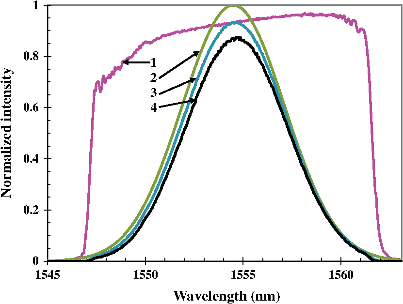 It is important to note that the reflection spectrum of a CBG is close to a tabletop profile while the emission spectra of pulsed lasers are close to Gaussian in shape (Fig. 5). This means that for efficient reflection of the whole spectrum of a laser system, which is determined by the full width at half maximum (FWHM) for a Gaussian function, a CBG should have about two times the spectral width of the FWHM for a tabletop function. One can see from Eq. (4) that for stretching a laser pulse to 1 ns, a CBG with a thickness of 100 mm is necessary. This means that for stretching to this pulse length and further recompression of a laser pulse in the vicinity of 1 μm, each spectral component propagates for 200 mm inside of a volume hologram recorded in PTR glass and crosses about 600,000 layers having a modified refractive index. This feature of the CBG technology necessitates strict requirements on the quality of the optical material (the optical homogeneity of PTR glass) and the quality of the holographic recording (the uniformity of the recorded interference pattern). This is why one of the most important parameters of a CBG is the divergence of the stretched and compressed ultrashort pulse laser beams. The most commonly used laser beam quality metric is the method accepted by the International Standardization Organization.23 The factor of a beam is calculated by measuring the dependence of the beam radius on the distance from a plane where the beam is focused by an aberration-free lens and compared to this dependence for a diffraction-limited Gaussian beam. is usually determined by the single diffraction of a beam with its spectral width adjusted to match the reflection spectrum of the CBG; this will be the metric for certification of CBGs. However, a number of applications based on threshold processes, e.g., ablation, require reliable data for the power density at the central spot of a laser beam on a target. This value has a good correlation with if it is below 1.1. To provide reliable power density data for CBGs providing higher , such a parameter as “power-in-the-bucket”24,25 is used. To enable a direct correlation of this parameter with measured by means of commercial devices, a cylindrical “bucket” can be substituted having two orthogonal slits enabling an easy comparison of “power-in-the-bucket” with in the corresponding directions. As it was mentioned in Sec. 1, the main limitation in power scaling of ultrashort pulse lasers is the instantaneous peak power density that triggers a number of detrimental nonlinear effects. A CPA reduces this power density in an amplified laser pulse inversely with the stretching time and, therefore, enables a corresponding increase in pulse energy after amplification. This is why an increase in stretching time is usually considered as a promising method for peak power/pulse energy scaling. Increasing the stretching time requires a proportional increase in the CBG thickness [Eq. (4)]. This is limited by the current technology for fabricating large size PTR glass wafers and for recording large aperture holograms. However, it is possible to increase the stretching time (and further decrease power density) by providing multiple passes of the laser pulse through the CBG (Ref. 26) or by designing multisectional devices consisting of several CBGs (Ref. 27) (Fig. 6). The multiple pass geometry for stretching and compression is produced by the use of mirrors and beam steering optical components that provide an increase in the time delay between the different spectral components. One can see in Fig. 4 that a double pass through the same grating provides doubling of the SF. Of course, this additional propagation length causes additional losses (about 8% in Fig. 5) but it enables a doubling of the stretching time and, therefore, almost double the pulse energy with the use of the same CPA device. It was shown in Ref. 27 that placing a sequence of several CBGs having adjacent reflection spectra and with proper spacing between them provides the same stretching and compression as a monolithic volume Bragg grating (VBG) with the same reflection spectrum and thickness. This approach enables the design of stretchers and compressors having an equivalent thickness that exceeds the current technological capability. Fig. 6Schematics of beam diffraction by multipass (a) and multisectional (b) CBGs. M—mirror, PM—phase mask. . Spatial modulation is not in scale—the typical period for a Bragg mirror at 1 μm is about 0.3 μm. 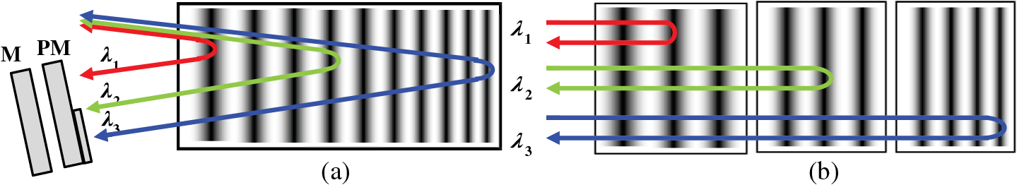 It should be noted that the use of multipass CBGs enables a new opportunity for pulse shape control.28 One can see in Fig. 6(a) that after the first diffraction in the multipass geometry, different spectral components are dispersed in a direction perpendicular to the direction of the beam propagation. Placing a phase mask between a CBG and a mirror [Fig. 6(a)] provides a phase shift between the different spectral components. This shift results in pulse distortions in the time domain. An example from modeling is shown in Fig. 7. One can see that placing a binary phase mask that provides a phase shift of for half of the beam (this means half of the pulse spectrum) causes a dramatic deformation in the pulse shape. It was found that the use of different phase masks could enable complex transformations in the pulse shape. Similarly, fine tuning of the spacing between sections of a multisectional compressor [Fig. 6(b)] provides a temporal shaping of the compressed pulse.27 3.CBGs Recorded in PTR GlassAs it was mentioned above, practical CBGs that can be installed in CPA ultrashort pulse laser systems became a reality when the technology of extremely high optical homogeneity PTR glass and the technology of extremely uniform large aperture hologram recording was demonstrated and made commercially available by the OptiGrate Corp, (Oviedo, Florida) ( www.optigrate.com). Currently, these technologies enable fabrication of CBGs for the spectral region from 0.8 to 2.5 μm with low absorption and high laser-induced damage threshold that ensures compression of pulses with an energy exceeding 1 mJ and an average power exceeding 250 W. The aperture for commercially available CBGs is up to with a thickness up to 50 mm. The level of diffracted beam quality that has been achieved for such CBGs is currently . A further extension of the aperture and thickness will be dependent upon achieving improvements in the PTR glass technology and large aperture hologram recording techniques. The characteristics of the CBGs recorded in PTR glass are a strong function of the spectral range where they are intended to be used because of the dramatic difference in the feasible SF (or SCR) and scattering loss for different spectral regions. There are four main spectral regions and CBG product types where commercially available laser sources may utilize CPA technology: type I CBGs for 0.8 μm Ti:Sapphire lasers; type II for 1 μm Yb and Nd doped fiber and solid state lasers, type III for 1.5 μm lasers based on Er-doped fiber and solid state lasers, and type IV for 2 μm novel laser sources that are currently under development. 3.1.Type I CBGs for 0.8 μmThe uses of CBGs in high power Ti:Sapphire laser systems have both positive and negative aspects. On the one hand, the use of CBGs is very beneficial since they can handle high peak powers. However, the use of CBGs in this short wavelength spectral region is limited due to the limited spectral bandwidth and high scattering losses that affect the diffraction efficiency. Figure 8(a) shows the dependence of the maximum achievable diffraction efficiency and the minimum achievable scattering losses on the spectral bandwidth of CBGs operating at 800 nm. It is known12 that an increase in the CBG spectral bandwidth requires a higher spatial refractive index modulation in the PTR glass. The maximum refractive index modulation in PTR glass of limits the achievable spectral width to about 20 nm for 800 nm operation. One can see that the diffraction efficiency decreases while the losses increase when the spectral width is increased. CBGs with a spectral bandwidth of 20 nm at 800 nm have diffraction efficiencies barely exceeding 50%. The main factor that restricts the diffraction efficiency of a CBG in this spectral range is the material losses caused by the light scattering in the bulk of the CBG material. As it was shown in the previous section, a decrease in the spectral width of CBGs in this region requires a smaller refractive index modulation and, therefore, smaller scattering losses [Fig. 8(a)]. CBGs designed for this spectral range can have SFs ranging from 15 to (Table 1). One can see that the maximum achievable SF is inversely proportional to the spectral bandwidth. From this table, one can calculate the maximum dispersion that can be provided by CBGs. For gratings having a spectral bandwidth from 2 to 20 nm, the achievable stretching time is 500 ps. Fig. 8Diffraction efficiency and losses achieved in chirped Bragg gratings versus spectral bandwidth for different wavelengths. 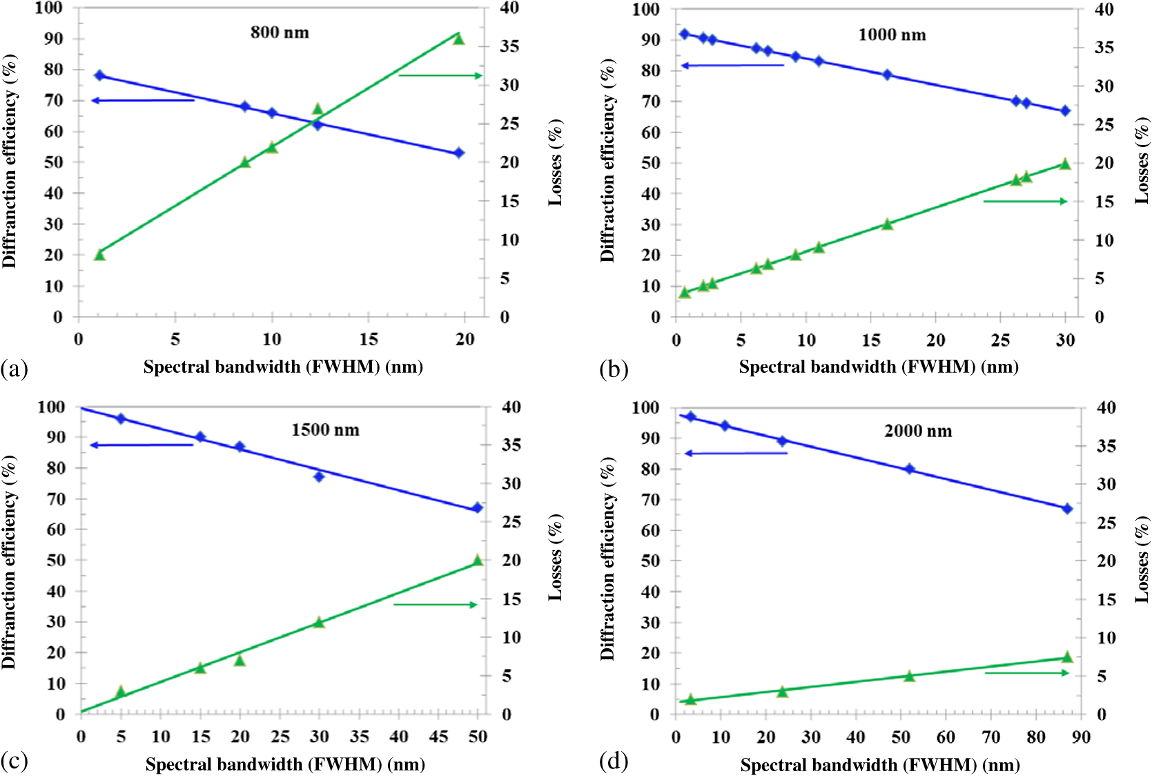 Table 1The parameters of chirped Bragg gratings used in the different spectral regions.
3.2.Type II CBGs for 1 μmIn this spectral region, a large variety of high power ultrafast lasers have been developed for industrial, medical, and military applications. The achievable characteristics of CBGs in this spectral region meet the requirements of those lasers very well and this has led to a wide range in the usage of CBGs in industrial and scientific ultrashort pulsed lasers at 1 μm. The main advantage of this spectral region for the use of CBGs is the reduced light scattering as described in Eq. (7). Thus, gratings fabricated for the 1 μm spectral range have significantly lower losses than for 0.8 μm. Figure 8(b) shows the achievable diffraction efficiencies for this spectral range and the associated losses for CBGs with different spectral bandwidths. One can see that the diffraction efficiency is significantly enhanced compared to the gratings designed for the 800-nm laser wavelength. This lower level of material losses has allowed fabrication of gratings with spectral bandwidths up to 30 nm. Currently, CBGs at 1 μm are commercially fabricated with SFs ranging from 7 to . Table 1 summarizes the achievable SFs for different spectral bandwidths. 3.3.Type III CBGs for 1.5 μmScattering losses in the 1.5 μm spectral range impose an even smaller penalty on the CBG diffraction efficiency. One can see in Fig. 8(c) that the material losses at 1500 nm are reduced by nearly a factor of two compared to those losses at 1000 nm with the same bandwidth. This permits the fabrication of CBGs having spectral bandwidths up to 50 nm. The manufacturing of gratings with a larger bandwidth in this spectral region is limited by the refractive index modulation. Table 1 summarizes the SFs for gratings operating in the 1500 nm spectral region. 3.4.Type IV CBGs for 2 μmThe transparency window of PTR glass extends out to 2.9 μm.17 Volume Bragg gratings with a uniform grating period operating at this wavelength have been successfully manufactured in PTR glass, however, the extended thickness needed for CBGs in this wavelength region reduces the transparency window down to 2.7 μm. Thus, this last type of VBG covers the region from 1800 to 2700 nm. In this region, the material losses due to scattering are smaller than 10% for all types of gratings. This is shown in Fig. 8(d), which also shows the achievable diffraction efficiency as a function of spectral bandwidth. In this spectral region, the main limiting factor that restricts the spectral bandwidth is the refractive index modulation. However, despite this limitation, CBGs with spectral bandwidths up to 100 nm can be designed and fabricated for the use in this spectral region. Recently, the technology of PTR glass fabrication has been significantly advanced enabling the manufacture of CBGs with thicknesses exceeding 50 mm and apertures exceeding 10 mm. The nearly diffraction-limited quality of the diffracted beam supports the usage of CBGs in high quality laser systems. 4.ConclusionsReflecting volume Bragg gratings recorded with the grating period gradually varying along the beam propagation direction provide effective stretching and recompression of short laser pulses. CBGs are monolithic devices that have three orders of magnitude smaller usage volumes compared to the conventional Treacy compressors. CBGs recorded in photo-thermo-refractive glass can be used in the spectral range from 0.8 to 2.5 μm with diffraction efficiencies exceeding 90%, and provide pulse stretching up to 1 ns and compression down to 200 fs for laser pulses with energies and average powers exceeding 1 mJ and 250 W, respectively, while keeping the recompressed beam quality . AcknowledgmentsThe work was partially supported by Navy contracts NN00024-09-C-4134 and N68335-12-C-0239 and HEL JTO contract W911NF-10-1-0441. ReferencesD. StricklandG. Mourou,
“Compression of amplified chirped optical pulses,”
Opt. Commun., 56
(3), 219
–221
(1985). http://dx.doi.org/10.1016/0030-4018(85)90120-8 OPCOB8 0030-4018 Google Scholar
E. Treacy,
“Optical pulse compression with diffraction gratings,”
IEEE J. Quantum Electron., 5
(9), 454
–458
(1969). http://dx.doi.org/10.1109/JQE.1969.1076303 IEJQA7 0018-9197 Google Scholar
O. Martinez,
“3000 times grating compressor with positive group velocity dispersion: application to fiber compensation in 1.3–1.6 μm region,”
IEEE J. Quantum. Electron., 23
(1), 59
–64
(1987). http://dx.doi.org/10.1109/JQE.1987.1073201 IEJQA7 0018-9197 Google Scholar
A. Boskovicet al.,
“All-fibre diode pumped, femtosecond chirped pulse amplification system,”
Electron. Lett., 31
(11), 877
–879
(1995). http://dx.doi.org/10.1049/el:19950611 ELLEAK 0013-5194 Google Scholar
A. Galvanauskaset al.,
“All-fiber femtosecond pulse amplification circuit using chirped Bragg gratings,”
Appl. Phys. Lett., 66
(9), 1053
–1055
(1995). http://dx.doi.org/10.1063/1.113571 APPLAB 0003-6951 Google Scholar
P. Hariharan,
“Optical holography. Principles, techniques, and applications,”
Practical Recording Materials, 95
–124 Cambridge University Press(1996). Google Scholar
V. A. Borgmanet al.,
“Photothermal refractive effect in silicate glasses,”
Sov. Phys. Dokl., 34
(11), 1011
–1013
(1989). SPHDA9 0038-5689 Google Scholar
L. B. Glebovet al.,
“Polychromatic glasses—a new material for recording volume phase holograms,”
Sov. Phys. Dokl., 35
(10), 878
–880
(1990). SPHDA9 0038-5689 Google Scholar
V. Smirnovet al.,
“Chirped bulk Bragg gratings in PTR glass for ultrashort pulse stretching and compression,”
in Proc. of Solid State and Diode Lasers Technical Review. Los Angeles,
SS2
–1
(2005). Google Scholar
K.-H. Liaoet al.,
“Large-aperture chirped volume Bragg grating based fiber CPA system,”
Opt. Express, 15
(8), 4876
–4882
(2007). http://dx.doi.org/10.1364/OE.15.004876 OPEXFF 1094-4087 Google Scholar
H. Kogelnik,
“Coupled wave theory for thick hologram gratings,”
Bell Syst. Tech. J., 48
(9), 2909
–2946
(1969). http://dx.doi.org/10.1002/bltj.1969.48.issue-9 BSTJAN 0005-8580 Google Scholar
I. V. CiapurinL. B. GlebovV. I. Smirnov,
“Modeling of phase volume diffractive gratings, part 1: transmitting sinusoidal uniform gratings,”
Opt. Eng., 45
(1), 015802
(2006). http://dx.doi.org/10.1117/1.2159470 OPEGAR 0091-3286 Google Scholar
I. V. Ciapurinet al.,
“Modeling of phase volume diffractive gratings, part 2: reflecting sinusoidal uniform gratings, Bragg mirrors,”
Opt. Eng., 51
(5), 058001
(2012). http://dx.doi.org/10.1117/1.OE.51.5.058001 OPEGAR 0091-3286 Google Scholar
S. Kaimet al.,
“Stretching and compressing of short pulses by chirped volume Bragg gratings: analytic and numerical modeling,”
Opt. Eng., 53
(5), 051509
(2014). http://dx.doi.org/10.1117/1.OE.53.5.051509 OPEGAR 0091-3286 Google Scholar
L. B. Glebov,
“Photochromic and photo-thermo-refractive (PTR) glasses,”
Encyclopedia of Smart Materials, 770
–780 John Wiley, New York
(2002). Google Scholar
T. Cardinalet al.,
“Comparative study of photo-induced variations of X-ray diffraction and refractive index in photo-thermo-refractive glass,”
J. Non-Cryst. Solids, 325
(1–3), 275
–281
(2003). http://dx.doi.org/10.1016/S0022-3093(03)00310-7 JNCSBJ 0022-3093 Google Scholar
L. Glebov,
“Fluorinated silicate glass for conventional and holographic optical elements,”
Proc. SPIE, 6545 654507
(2007). http://dx.doi.org/10.1117/12.720928 PSISDG 0277-786X Google Scholar
J. LumeauL. GlebovaL. B. Glebov,
“Near-IR absorption in high-purity photothermorefractive glass and holographic optical elements: measurement and application for high-energy lasers,”
Appl. Opt., 50
(30), 5905
–5911
(2011). http://dx.doi.org/10.1364/AO.50.005905 APOPAI 0003-6935 Google Scholar
D. R. Drachenberget al.,
“Ultimate efficiency of spectral beam combining by volume Bragg gratings,”
Appl. Opt., 52
(30), 7233
–7242
(2013). http://dx.doi.org/10.1364/AO.52.007233 APOPAI 0003-6935 Google Scholar
“Lasers and laser-related equipment—test methods for laser beam widths, divergence angles and beam propagation ratios,”
Geneva, Switzerland
(2005). Google Scholar
A. E. Siegman,
“Defining, measuring, and optimizing laser beam quality,”
Proc. SPIE, 1868 2
–12
(1993). http://dx.doi.org/10.1117/12.150601 PSISDG 0277-786X Google Scholar
S. RossW. P. Latham,
“Appropriate measures and consistent standard for high energy laser beam quality,”
J. Dir. Energy, 2
(1), 22
–58
(2006). Google Scholar
O. Andrusyaket al.,
“Sectional chirped volume Bragg grating compressors for high-power chirped-pulse amplification,”
Proc. SPIE, 7578 75781A
(2010). http://dx.doi.org/10.1117/12.845941 PSISDG 0277-786X Google Scholar
D. Moseset al.,
“Stretching and compression of ultrashort pulses using chirped volume Bragg gratings in single- and multi-pass configurations,”
in Advanced High Power Laser Review, 8th Annual Ultrashort Pulse Laser Workshop,
(2010). Google Scholar
BiographyLeonid Glebov received PhD from the State Optical Institute, Leningrad, Russia (1976). He is a research professor at CREOL/UCF and co-founder and VP at OptiGrate Corp. He is a coauthor of a book, more than 300 papers and 10 patents. He is a fellow of ACerS, OSA, SPIE, and NAI. He is a recipient of the Gabor award in holography. His main directions of research are optical properties of glasses, holographic optical elements, and lasers. Vadim Smirnov received MS in optics at CREOL, University of Central Florida in 2000. He is a co-founder, Director of Holography and Chief Technology Officer at OptiGrate Corp. He is the coauthor of more than 100 presentations and publications and three U.S. patents on high-efficiency diffractive elements in photo-thermo-refractive glass. His research activities include design and fabrication of volume diffractive gratings and holograms, nonlinear phenomena in optical glasses, and laser design. Eugeniu Rotari received MS in Chemistry in 2002 from the State University of Moldova, Chisinau. In 2002 he joined CREOL/UCF as a research scientist. Since 2005 he has been employed at Optigrate as a group leader focusing on optimization of volume Bragg grating recording in PTR glass, and automation of the testing and characterization of holographic optical elements. He participated in the development of recording and testing technologies for chirped Bragg gratings in PTR glass. Ion Cohanoschi received his PhD in optics from the University of Central Florida, Orlando, USA, in 2006. From 1995 to 2000. He held the position of physicist at the Nuclear Research Institute at Pitesti, Romania. Currently, he is a senior production engineer at OptiGrate and is responsible for the fabrication of Chirped Bragg Gratings (CBGs) and quality control of all VBGs. He has 17+ publications in refereed scientific journals and conference proceedings. Larissa Glebova received her MS in organic chemistry from Tomsk Polytechnic Institute (Russia). She is affiliated with CREOL/UCF as a research scientist and with OptiGrate Corp. as a co-founder and principal glass scientist. She is the co-author of 41 publications in scientific journals and holds two patents. The principal directions of Ms. Glebova’s research include the technology of high purity homogeneous photosensitive glass, photo-thermo-induced structural transformations in glass, and the spectroscopy of glasses. Oleg Smolski received the PhD in physics from Physico-Technical Institute in St Petersburg, Russia, in 1986. His research activity covers semiconductor structures, epitaxial growth, optical glass melting, processing, and packaging of laser diodes and optical glass components, and developing light-emitting devices with in-plane integrated and externally assembled diffractive optical elements. Currently he is a manager of a glass technology division at OptiGrate Corp. He is the co-author of over 50 scientific papers. Julien Lumeau received PhD in physics from the Fresnel Institute, Marseille University, France in 2004. From 2005 until 2012, he worked as a research scientist at CREOL/UCF and as a consultant at OptiGrate Corp. In 2013, he returned to Fresnel Institute as a CNRS senior research Scientist. He is a coauthor of over 100 scientific publications. The directions of his research are photosensitive materials including their optical, nonlinear and crystallization properties. Christopher Lantigua received his BS degree in electrical engineering from University of Florida in Gainesville, Florida and MS degree in optics from University of Central Florida. He is now pursuing his PhD degree in optics from the College of Optics and Photonics at the University of Central Florida in Orlando, Florida. His current research interests include holographic optical elements and nanophotonics. Alexei Glebov is CEO and President of OptiGrate Corp. He received PhD in applied physics from University of Gottingen, Germany. His career includes Bell Laboratories, Finisar, Fujitsu, and Lucent Technologies. He has 35 US patents and more than 50 peer-reviewed journal publications and book chapters. He is a frequent invited lecturer, editor of conference proceedings, conference and symposium chair, and executive organizing and program committee member at professional photonics meetings and trade shows. |
||||||||||||||||||||||||||||||||||||||||||||||||||||||||||||||||||||||


