|
|
1.IntroductionCurrently, light-emitting diodes (LEDs) are widely used in a backlight unit for a liquid crystal display (LCD). In a direct-lit backlight unit, LEDs are laid out on a plane and a diffuser sheet is placed above them. The space between them mixes the light from each LED and the two-dimensional array of point sources is converted to a planar source. In an edge-lit unit, LEDs are attached at an edge of a transparent plate (light-guide plate), and the light propagates inside by repeating total internal reflection. Some microstructures (output couplers) formed on the plate extract the light toward a liquid crystal panel. A uniform planar source can be realized by a careful design of output couplers. Several authors have addressed this problem and invented various configurations. Naturally, they have different names such as hybrid prism coupler,1 grating prism array,2 optically patterned film,3 grating microdots,4 and polydimethylsiloxane light-guide plate.5 Because these structures are designed not only for out-coupling the light but also for controlling its emission directions, one can eliminate optical films normally used in a direct-lit unit such as a diffuser sheet and a prism sheet. For example, a backlight unit as thin as 0.26 mm has been reported.6 Therefore, edge-lit units are particularly suited for mobile applications. As a light-guide plate becomes thinner than the emission area of an LED, butt-coupling is not efficient any more. One can alleviate this problem by inventing some optical means (input couplers).7,8 Alternatively, we can use a light source with a small etendue. In optical communication, the light from a laser diode (LD) is efficiently coupled into an optical fiber. The cladding diameter of an optical fiber is typically 0.125 mm and the core diameter is 0.05 mm for a multimode fiber and 0.009 mm for a single-mode fiber. Therefore, an LD can be coupled to a 0.125-mm thick light-guide plate via an optical fiber with a good efficiency. Knowledge accumulated in the communication industry is available for the display community. Laser technology has been applied for a large-scale projector9 as well as for a direct-view LCD.10 Coherent light from a laser undergoes reflections at different locations on a screen or in the components that constitutes an LCD. When the coherent light enters our eyes from many directions, an image formed on our retinas contains a number of bright and dark spots. This interference effect, so-called speckle, disappears when we use phosphors with a blue LD.11 This approach of course degrades the color reproducibility of a display. The use of multiple lasers emitting at different wavelengths is preferred to realize a much wider color gamut. In such a case, speckle must be properly dealt with. One of the solutions is to apply ultrasound vibrations for an optical fiber. The vibration rapidly changes phase retardation in the optical fiber, and the interference patterns are averaged out.12 At present, however, the cost associated with LDs seems to be an inhibiting factor for direct-view applications. The quantum dot backlight technology13,14 might be an interim solution toward a wide-gamut LCD. The combination of red LDs and cyan LEDs is another approach. In 2012, Mitsubishi Electric Corp. commercialized a television set equipped with such a backlight unit.15 Because the two light sources have different emission characteristics, two types of light-guiding structures are needed for each light source, and they are stacked together. No optical fibers are used to isolate the heat flow from the LDs, and thermal management plays an important role for stable operation. Also in 2012, we reported a backlight unit based on a leaky optical fiber.16 Multiple grooves were fabricated on a plastic optical fiber (POF) to extract the light at desired points. The shape and depth of the grooves determine emission characteristics.17 Such a backlight configuration offers design freedom for future LCD applications. In this paper, the idea of a leaky optical fiber is extended. Rather than fabricating grooves, we propose to utilize the so-called bend loss for distributing laser light over a large area. Bend loss must be avoided in optical fiber communication. In our application, however, we deliberately curve a POF and let the light leak out. A characterization of the light leakage from a curved POF is described in the next section. A demonstration of prototypes is described in the following section. Finally, we discuss some design issues and conclude. Merits expected from this configuration based on bend loss include efficient use of laser light, ease of designing a large, arbitrary-shaped backlight unit, and the possibility of making a see-through display. 2.Light Extraction from a Curved POFThe phenomenon known as bend loss or curvature loss has been well studied for optical communications.18 As the term indicates, emphasis is on the power remaining in an optical fiber even for a sensor application.19 Because we wish to distribute laser power via a POF with multiple curved sections, our interest is in the characteristics of the leaking light. We have carried out the following experiments to reveal two key features; the intensity and angular distribution of the leaking light. 2.1.Light Extraction EfficiencyAs illustrated schematically in Fig. 1(a), we place a POF in one of the multiple trenches fabricated on the surface of a transparent acrylic plate. The light from a green laser enters one end of the POF and exits from the other end. A power meter is placed at the end of the POF to record the power exiting the POF. This is denoted as . When the POF is not placed in the trenches, there is no bend loss. We denote this output as . The difference of is the power leaked into the transparent plate from a curved section of radius . We define light extraction efficiency as follows: Fig. 1Measurement of light extraction efficiency. (a) Curved trenches are fabricated in a transparent plate to set a radius of curvature. (b) Extraction efficiency is evaluated for two plastic optical fibers (POFs) with different diameters. Based on these curves, we can set by selecting the radius of curvature. 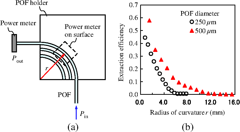 We repeated this measurement for two step-index, multimode POFs with different core diameters (250 and 500 μm). Information on the components and equipment used in this experiment is summarized in Table 1. As shown in Fig. 1(b), varies monotonically with the radius of curvature. Note that these numbers refer to the power extracted from a quarter of a circle in this measurement. We can set light extraction efficiency to a desired value by selecting the radius of the curvature as well as the diameter of a POF. For simplicity, however, we use only the 500-μm diameter POF in the experiments described here. Table 1Components and equipment used in this experiment.
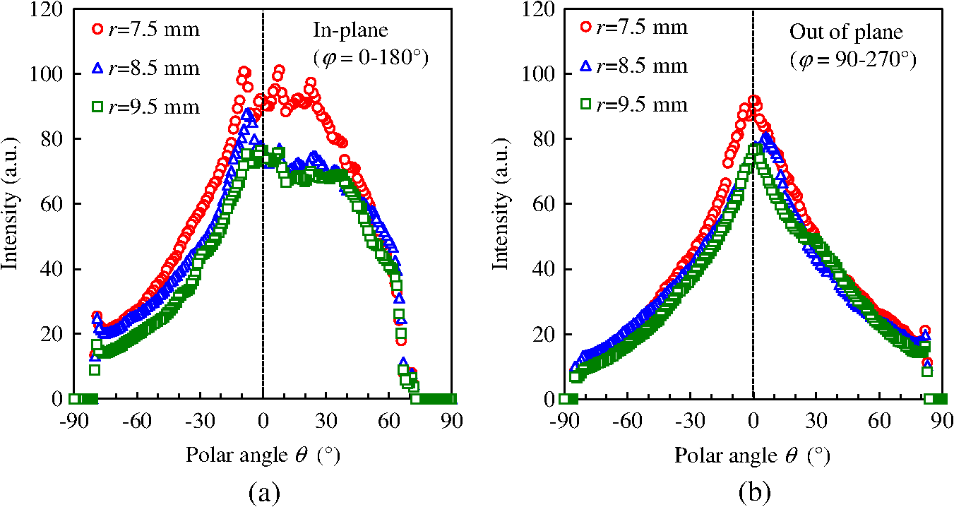
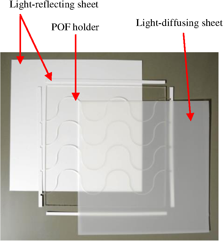
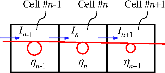
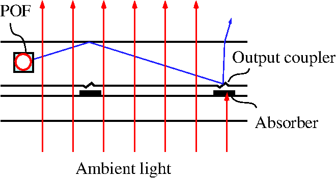
It should be noted that there was a small air gap around the POF in the trenches due to mechanical tolerance for placing the POF. We filled this gap with an index-matching oil and repeated the measurement for the 500-μm diameter POF. The discrepancy from the data in Fig. 1(b) was insignificant. We also tried to measure the power exiting from the top surface of the curved trenches. There was no detectable output from the surface () while we set to 1 mW. 2.2.Angular DistributionUsing a measurement system called ImagingSphere,20 we evaluated the angular distributions of the light leaking from a curved section for the 500-μm diameter POF. The experimental setup and the definitions for the coordinate system, polar angle and azimuth angle are illustrated in Fig. 2. Black cylinders with known radii were used to set the radius for the POF. Fig. 2Setup for measuring angular distributions of the light exiting from a curved section of the 500-μm diameter POF. The light enters the aperture of ImagingSphere placed nearby. 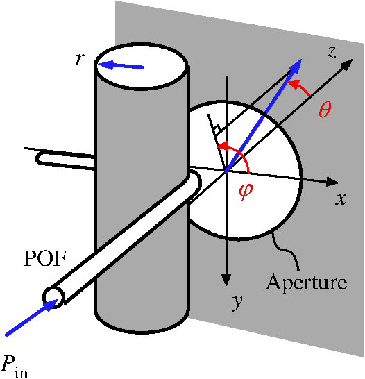 The results for three different curvature settings are compared in Fig. 3. The radial coordinate and the angular coordinate in these diagrams correspond to the polar angle and the azimuth angle defined in Fig. 2, respectively. The intensity of the light is color-coded. The color bar in Fig. 3 is common for the three distributions. The distributions in the plane containing the POF are stretched and asymmetric while their relative intensity distributions are similar irrespective of the radius of curvature. The intensity increases at a smaller radius; this is consistent with Fig. 1(b). The data are missing in the angular range of and due to the limitation of the apparatus.20 Fig. 3Angular distribution of the light exiting a curved section of the POF. The color bar is common for the three distributions. 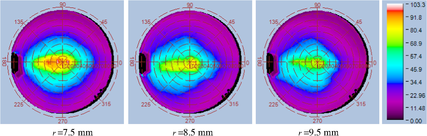 For a closer observation, intensity profiles in two planes are plotted in Fig. 4. Aside from the small shift of the peak for the curve in the out-of-plane profile, which is probably caused by an error in aligning the POF, the quick observations above are confirmed. Ideally, we wish to contain all the light inside a transparent plane. However, the distributions in the plane perpendicular to the POF layout extends close to . Note that the POF was surrounded by air. We will discuss this point in Sec. 4. 3.Prototype UnitsBased on the measured extraction efficiency and without much design considerations, we have fabricated two types of backlight units with off-the-shelf components. These are proof-of-concept experiments from which we intend to identify key design issues. 3.1.Opaque VersionFirst, we extend the idea of the backlight unit described in our previous paper.16 Instead of fabricating grooves in a POF, we simply place the 500-μm diameter POF in a curved trench. Components used here are shown in Fig. 5 and listed in Table 1. The POF holder () is made of an acrylic plate. Curved trenches are fabricated on its surface by numerically controlled machining. The cross section of the trench is , and an air-gap exists around the POF. For simplicity, the radius of curvature is fixed at 9.5 mm () so that 3.67% of the optical power is extracted at each 90 deg-turn of the POF. Only one POF is used to connect these four wave-shaped trenches. Because there are 40 90 deg-turns in this POF holder, the fraction of the power remaining in the POF after the last turn is calculated to be . The square reflector sheet is placed 1 mm below the POF holder. The narrow reflector sheets are attached to the four side walls of the POF holder except for the places where the POF gets through. We vary the distance between the POF holder and the diffuser sheet and capture images of the module with a digital camera. We call the POF pattern in Fig. 5 as Type A. The experiment is repeated with another POF pattern (Type B) in which the radius of the curvature is set to 8.5 mm (). The power remaining in the POF after 50 turns is calculated to be . The module for each POF pattern is shown in Fig. 6. When the diffuser sheet is placed 0.2 cm above the POF holder, the POF pattern is clearly visible in Figs. 6(a) and 6(c). The pixel values in these images are proportional to the intensities of the light extracted from the corresponding areas of the prototypes. These values are much more uniform than what we expect from the factor , where is the number of the curved section of the POF. It is interesting to note that the downstream is almost as bright as the upstream and that the straight sections of the POF are also bright. This is because the light extracted from each curved section of the POF mixes together inside this plate. The light undergoes reflections and refractions at the structure around the POF and eventually exits the plate. Therefore, the trench-POF structure performs two functions. First, it distributes the optical power over an area. Second, it out-couples the light from the plate. These POF layout patterns become less visible when the distance becomes larger than 2 cm. Nevertheless, these modules are thick and opaque because of the reflector sheet and the diffuser sheet. Fig. 6Photographs of the two area prototype modules. (a) When the diffuser-holder distance is 0.2 cm, the POF layout pattern is clearly visible. (b) When the diffuser sheet is placed 2.0 cm above the POF holder, luminance uniformity is improved. The same observation holds for the second POF pattern in (c) and (d). 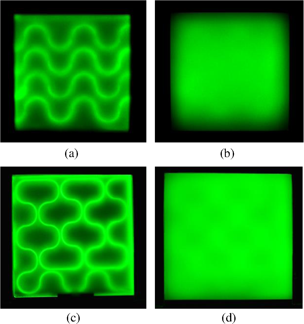 3.2.See-Through VersionAs illustrated in Fig. 7(a), we fill the air gap around the POF with index-matching oil. A transmissive, diffraction-grating film is attached to the POF holder via the same oil to out-couple the light inside. This is not an ideal solution because a diffraction grating generates rainbow colors when illuminated by a white point source. Although a sparsely placed, nonperiodic microstructure is preferred, we have chosen to use a readily available component for quick prototyping. Because the reflector sheet and the diffuser sheet are removed, this configuration becomes see-through. The POF layout pattern becomes almost invisible but not completely due to the small mismatch in the indices of refraction. In the example shown in Fig. 7(b), Type B holder is used, and the light is fed into the POF from the top-right corner. Although the light is extracted from the whole area, the right-hand side of the unit is brighter. This nonuniformity is caused by the power depletion inside the POF. We will discuss a solution to this problem in Sec. 4.1. Without the oil, the POF pattern is clearly visible as shown in Fig. 7(c). Its brightness is similar along the path because the light extracted by the curved sections can travel a long distance inside the plate. It is the trench-POF structure (not the grating film) that performs the function of an output coupler in this case. Fig. 7A see-through version of the square prototype unit. (a) A diffraction-grating film is attached to the transparent plate to extract the light inside. (b) The light is extracted by the diffraction-grating film. (c) When there is no index-matching oil, the light exits from the POF-trench structures. 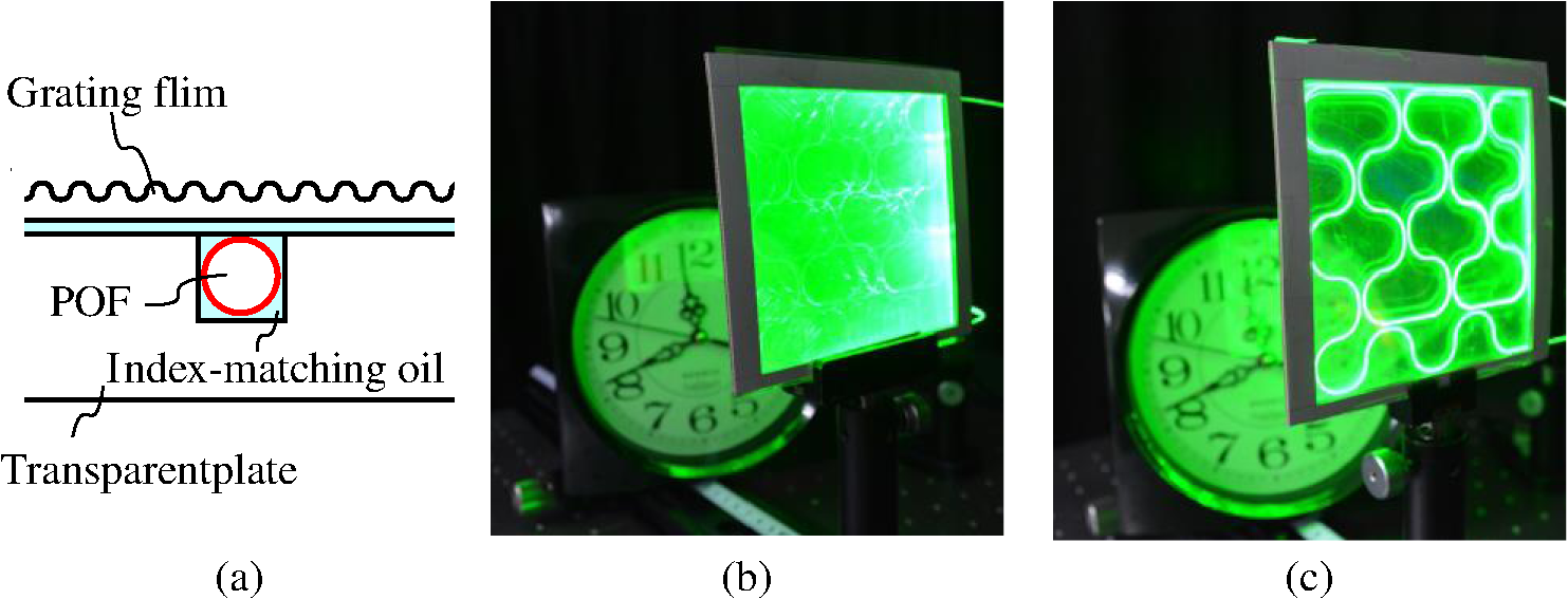 To demonstrate a design versatility, we have fabricated a spade-shaped backlight unit. As shown in Fig. 8(a), there are nine large circles and three small circles in a 3-mm thick POF holder. The numbers in this figure are in millimeters. The same POF and the grating film are used for this version with the unit shown in Fig. 7. The laser light enters the POF from the lower right edge and exits from the bottom circle. The trench in this holder is 1.2-mm deep to allow the 500-μm diameter POF to cross each other. The side wall of this acrylic plate is covered by reflector sheets except for the two locations where the POF gets through. A close observation of the OFF-state photograph in Fig. 8(b) reveals that the image of the object behind the module is slightly distorted. It also shows a trace of the POF pattern. These are caused by diffraction and refraction of the light passing through the grating film and the trench-POF structure. In Fig. 8(c), the ON-state shows that the lower-right region is brighter for the same reason discussed above. The enlarged picture shows that the POF trace is brighter than the surrounding area. This is caused by a slight mismatch in the indices of refraction. Fig. 8A spade-shaped prototype unit fabricated with off-the-shelf components. (a) The trench for placing a POF in the acrylic plate contains 12 circles. (b) When the laser is turned off, the clock behind the unit is visible. (c) When the laser is turned on, the light is emitted from the whole area. 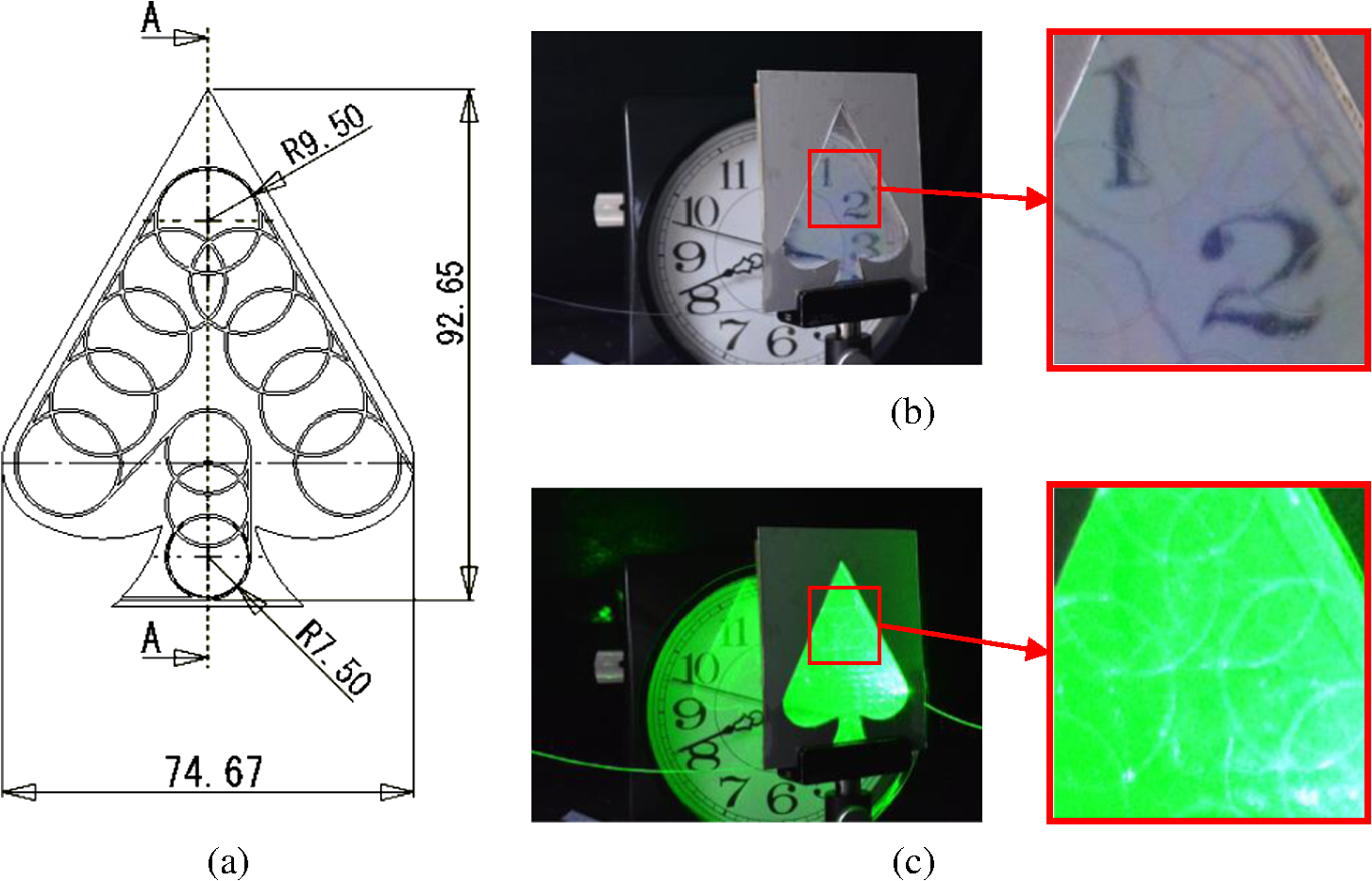 In Figs. 7(b) and 8(c), the clock behind the prototype unit is illuminated by the green laser light. This indicates that some light is emitted backward from our prototype units. The backward emission is caused by the output couplers [the POF-trench structure in Fig. 7(b) and the grating film in Fig. 8(c)]. Since backward emission is a loss, it should be minimized by a careful design of output couplers. This design issue is common to very thin edge-lit backlight units in which some optical films are eliminated. Many authors have addressed this problem in the past.1–6 In the future, a similar study on this subject is desired for our configuration as well. 4.DiscussionMany laser applications require highly efficient input coupling between LDs and optical fibers. A problem unique to our configuration is how to distribute the optical power uniformly and efficiently over a large area. Another unique problem is how we improve the transparency of see-through backlight units. These two are related, and they can be solved by some optical design considerations. This is the first topic we discuss in this section. Our approach for a see-through backlight unit might pave the way for new applications. Several authors have discussed transparent displays based on various technologies. In the second half of this section, we will discuss potential advantages of our approach. 4.1.Uniform and Efficient Delivery of Optical PowerWe adopt a modular design for delivering optical power over a large area. Namely, we propose to tile multiple cells and connect them via an optical fiber. This is carried out with two steps. The first step is a global power distribution. We require that the same amount of optical power is delivered to each cell through an optical fiber. The second step is a local power distribution, that is, efficient and uniform light extraction from a cell while maintaining a certain level of transparency. These two steps are considered in order. 4.1.1.Global power deliveryWe start our discussion by assuming that the surface area and the shape of each cell are identical. An example of square cells connected by an optical fiber is illustrated in Fig. 9. We assume that each cell is optically isolated except for the power flowing in and out through the optical fiber. This can be achieved by attaching very thin reflector sheets on the four side walls. Referring to the ’th cell in Fig. 9, the power delivered to this cell is expressed as , where and are the power entering the cell and the extraction efficiency of the curved section in this cell, respectively. We require that this factor () is constant for all cells. For example, we can adjust the radius of each circle and/or the length of curved section. Suppose that the total number of cells is and the initial power entering the first cell is . Then, the following equations hold: The solution for the recurrence equation is given by From Eqs. (2) and (4), the power in the optical fiber is given by A sample calculation for the case of and is shown in Fig. 10. The power in the optical fiber () decreases linearly with the cell number (), and the extraction efficiency () is inversely proportional to . Therefore, the power delivered to each cell is constant. As shown in Fig. 1(b), the values for calculated here can actually be realized. Fig. 10Sample calculation for the extraction efficiency and the optical power remaining in the POF at each cell. 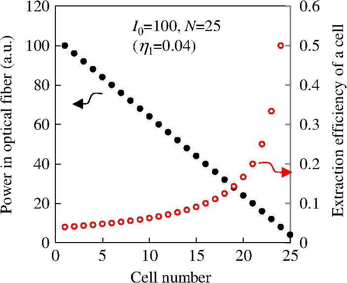 Under the assumption that we could reproduce the calculated distribution of extraction efficiency, global power delivery is loss-less and uniform in principle. However, in practice, a POF experiences irrecoverable deformation at an extremely small radius of curvature. The extraction efficiency for the last two cells in Fig. 10 might be too high for the 500-μm diameter POF. We could flatten the distribution of the extraction efficiency by placing a reflector at the end of an optical fiber in case such a need arises. A similar strategy has been applied for designing the distribution of output couplers in an edge-lit backlight unit.3 4.1.2.Local power deliveryNow that equal power is delivered to each cell, we concentrate on how to out-couple the light uniformly and efficiently from a cell. The geometry at hand is illustrated in Fig. 11. Let us assume for a moment that the region around the POF is air. The light leaked from the POF enters the plate with refraction at the boundary. If the propagation angle is smaller than a certain critical value, it is contained in the plate by total internal reflections at the plate-air interface. The reflectors attached to the side walls bounce the light back. Unless the plate is extremely thin, the light hits the microstructures eventually. Fig. 11Configuration for out-coupling the light from a cell. (a) For example, a circle is formed at the center of a light-guide plate by laying out a POF. Side walls of the plate reflect the light. Microstructures (output couplers) are distributed concentrically. (b) There is no reflector sheet below the plate for a see-through unit. 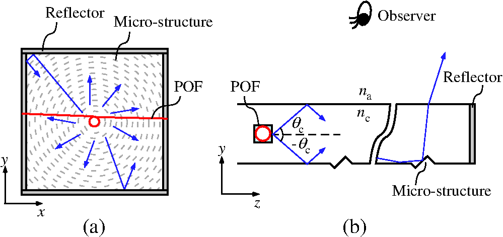 Design considerations for this light-guide plate are similar to those encountered in optimizing an edge-lit backlight unit. Ray tracing simulation is used to fine-tune the shape and distributions of output couplers.1,3 The basic idea for uniform light extraction is to compensate the light depletion inside a light-guide plate by increasing the density of output couplers. In our configuration, there are two unique points worthy of attention. First, we prefer to place a curved section of a POF at the center of a light-guide plate. For example, we can distribute output couplers concentrically and adjust their radii for uniform light extraction. This design reduces the average distance that the light travels inside the plate before extraction. Therefore, it decreases the density of the microstructures and improves transparency of the cell. Note that the microstructures not only extract the light from the cell but also change the directions of the light passing through the cell. Second, a reflector sheet is not allowed in a see-through unit. If the light were emitted to the opposite side of an observer, it would be lost. This light loss would set an upper limit for light utilization. We can roughly estimate it as follows. Let and be the index of refraction for the air and the plate, respectively. The critical angle for total internal reflection, as defined in Fig. 11(b), is given by Suppose that represents an angular distribution of the light emitted from a curved section of a POF. The probability for the light loss is expressed as follows: Note that we have measured angular distributions of the light emitted to the air (see Fig. 3). We can convert this to in an acrylic plate with by applying Snell’s law once. The range for the propagation angle in the acrylic plate is given by . Because , the factor becomes zero. Therefore, the efficiency of a unit cell can be as high as an edge-lit unit. 4.1.3.Distortion and transparencyAs shown in the enlarged photograph in Fig. 8(b), the image of an object behind the prototype unit is distorted because the diffraction-grating film changes the direction of the light passing through. Refractive and/or reflective elements are also used as output couplers in an edge-lit backlight unit.1,3,5 These elements would also distort images because they would alter the direction of the ambient light as well. Output couplers are required for an edge-lit backlight unit but they degrade see-through images. There is a simple solution for this dilemma as shown in Fig. 12. By stacking a mask plate with an array of absorbers, we block the light that would otherwise hit the output couplers. If we make the area for the local power delivery small enough, output couplers can be sparsely distributed. In such a case, transmittance remains relatively high. Although each cell might be small, we connect them with an optical fiber to cover a large area. This is an advantage of a modular design. 4.2.Transparent DisplaysApplications of a small see-through display include head-up displays for wearable computers, augmented realities, and automobiles. A large-scale transparent display is applied for showcases at stores. The latter is based on a liquid crystal panel without a backlight unit. External lighting is required to illuminate products inside a showcase and to show their prices and other information on the liquid crystal panel. Oxide transistor technology increases the transmission of such a panel.21,22 Other technologies, such as plasma23 and organic light emitting diode (OLED),24 are also studied for large-scale transparent display applications. A liquid crystal panel equipped with a see-through backlight unit would find more applications beyond showcases at stores. For example, it can be attached to the windshield in an automobile to provide maps and other navigation information to a driver. The space required for a current head-up display to project images will be eliminated. Transparent OLED technology offers the same advantage of flatness but the light is emitted from the two transparent electrodes. Half of the light is not utilized for displaying information. In our backlight unit, most of the light is emitted from one surface. 5.ConclusionsWe have proposed utilizing light leakage from the curved sections in a POF for constructing a backlight unit. The efficiency for transferring the light inside a POF into a light-guide plate can be controlled by selecting the diameter and the radius of curvature of a POF. No detectable optical power leaks out of the light-guide plate from the curved section of the POF. Combined with good input coupling between a LD and a POF as well as the output coupling technologies developed for the conventional edge-lit backlight units, we expect highly efficient usage of light for the configuration proposed here. We have fabricated opaque and see-through prototype units with off-the-shelf components to advance design considerations. First, we can adopt a modular design where each cell is optically isolated and multiple cells are connected by a POF. By setting extraction efficiency for each cell, we can compensate the light depletion inside the POF downstream. This design allows us to deliver optical power efficiently and uniformly over a large arbitrary-shaped area. Second, output couplers on a light-guide plate can distort the passage of ambient light. For a see-through unit, we can distribute them sparsely and/or use absorbers to prevent ambient light from entering output couplers. Although an OLED with two transparent electrodes emits light from both surfaces, the unit proposed here emits most of the light from one surface. An LCD with a see-through backlight unit might be attached to the windshield in an automobile to provide navigation information to a driver. AcknowledgmentsWe would like to thank the members of the Machine Shop at Ritsumeikan University for their assistances in fabricating the prototype units described in this paper. ReferencesS. AoyamaA. FunamotoK. Imanaka,
“Hybrid normal-reverse prism coupler for light-emitting diode backlight systems,”
Appl. Opt., 45
(28), 7273
–7278
(2006). http://dx.doi.org/10.1364/AO.45.007273 APOPAI 0003-6935 Google Scholar
G. Kurataet al.,
“Sheetless backlight system for mobile phone,”
in Proc. of 13th Int. Display Workshops,
1727
–1730
(2006). Google Scholar
K. FujisawaI. OnishiY. Fujiwara,
“Edge-light backlight unit using optically patterned film,”
Jpn. J. Appl. Phys., 46
(1), 194
–199
(2007). http://dx.doi.org/10.1143/JJAP.46.194 JJAPA5 0021-4922 Google Scholar
S. R. Parket al.,
“Grating micro-dot patterned light guide plates for LED backlights,”
Opt. Express, 15
(6), 2888
–2899
(2007). http://dx.doi.org/10.1364/OE.15.002888 OPEXFF 1094-4087 Google Scholar
J.-H. Leeet al.,
“Simple liquid crystal display backlight unit comprising only a single-sheet micropatterned polydimethylsiloxane (PDMS) light-guide plate,”
Opt. Lett., 32
(18), 2665
–2667
(2007). http://dx.doi.org/10.1364/OL.32.002665 OPLEDP 0146-9592 Google Scholar
A. Nagasawaet al.,
“Ultra slim and bendable backlight system with a unified component for liquid crystal display applications,”
Opt. Rev., 15
(1), 38
–43
(2008). http://dx.doi.org/10.1007/s10043-008-0007-y 1340-6000 Google Scholar
H. SuzukiM. HiguchiY. Yang,
“Twisted S-shaped light pipe for highly efficient coupling between LED and lightguide in backlight system,”
SID Int. Symp. Dig. Tech. Pap., 38 38
–41
(2007). http://dx.doi.org/10.1889/1.2785220 0097-966X Google Scholar
T. MurataI. Fujieda,
“Input couplers for thin light-guides and LEDs,”
Opt. Eng., 47
(2), 027001
(2008). http://dx.doi.org/10.1117/1.2838592 OPEGAR 0091-3286 Google Scholar
M. Jansenet al.,
“Large venue laser-based projectors,”
in Proc. of 14th Intl. Display Workshops,
2353
–2356
(2007). Google Scholar
Y. InabaY. NagaiI. Fujieda,
“Edge-lit backlight utilizing a laser diode and an optical fiber,”
in Proc. of 14th Int. Display Workshops,
705
–708
(2007). Google Scholar
Y. Inabaet al.,
“A backlight based on a laser diode and its design considerations,”
SID Int. Symp. Dig. Tech. Pap., 39 1564
–1567
(2008). http://dx.doi.org/10.1889/1.3069459 0097-966X Google Scholar
I. FujiedaT. KosugiY. Inaba,
“Speckle noise evaluation and reduction of an edge-lit backlight system utilizing laser diodes and an optical fiber,”
J. Disp. Technol., 5
(11), 414
–417
(2009). http://dx.doi.org/10.1109/JDT.2009.2027612 JDTEDS 0193-2691 Google Scholar
E. Janget al.,
“White-light-emitting diodes with quantum dot color converters for display backlights,”
Adv. Mater., 22 3076
–3080
(2010). http://dx.doi.org/10.1002/adma.v22:28 ADVMEW 0935-9648 Google Scholar
T.-H. Kimet al.,
“Full-colour quantum dot displays fabricated by transfer printing,”
Nat. Photonics, 5 176
–182
(2011). http://dx.doi.org/10.1038/nphoton.2011.12 1749-4885 Google Scholar
N. Nakanoet al.,
“Laser backlighting LCD TV,”
in 2013 Conf. Lasers and Electro-Optics Pacific Rim (CLEO-PR),
(2013). http://dx.doi.org/10.1109/CLEOPR.2013.6599918 Google Scholar
Y. OkudaK. OnodaI. Fujieda,
“Laser backlight unit based on a leaky optical fiber,”
Opt. Eng., 51
(7), 074001
(2012). http://dx.doi.org/10.1117/1.OE.51.7.074001 OPEGAR 0091-3286 Google Scholar
K. YasuS. KojimaI. Fujieda,
“Light extraction from plastic optical fibers for laser backlight units,”
in the 2nd Laser Display Conf.,
(2013). Google Scholar
R. T. SchermerJ. H. Cole,
“Improved bend loss formula verified for optical fiber by simulation and experiment,”
IEEE J. Quantum Electron., 43
(10), 899
–909
(2007). http://dx.doi.org/10.1109/JQE.2007.903364 IEJQA7 0018-9197 Google Scholar
S. OtsukiK. AdachiT. Taguchi,
“A novel fiber-optic gas-sensing configuration using extremely curved optical fibers and an attempt for optical humidity detection,”
Sens. Actuators B, 53 91
–96
(1998). http://dx.doi.org/10.1016/S0925-4005(98)00296-2 SABCEB 0925-4005 Google Scholar
R. RykowskiD. KreysarS. Wadman,
“The use of an imaging sphere for high-throughput measurements of display performance—technical challenges and mathematical solutions,”
SID Int. Symp. Dig. Tech. Pap., 37 101
–104
(2006). http://dx.doi.org/10.1889/1.2433146 0097-966X Google Scholar
T.-J. HaA. Dodabalapur,
“Photo stability of solution-processed low-voltage high mobility zinc-tin-oxide/ZrO2 thin-film transistors for transparent display applications,”
Appl. Phys. Lett., 102 123506
(2013). http://dx.doi.org/10.1063/1.4795302 APPLAB 0003-6951 Google Scholar
S. Leeet al.,
“Red-green-blue light sensitivity of oxide nanowire transistors for transparent display applications,”
AIP Adv., 3
(1), 012112
(2013). http://dx.doi.org/10.1063/1.4789405 AAIDBI 2158-3226 Google Scholar
C. JangK. KimK. C. Choi,
“Toward flexible transparent plasma display: optical characteristics of low-temperature fabricated organic-based display structure,”
IEEE Electron Dev. Lett., 33 74
–76
(2012). http://dx.doi.org/10.1109/LED.2011.2171314 EDLEDZ 0741-3106 Google Scholar
J. Yeonet al.,
“Actively transparent display with enhanced legibility based on an organic light-emitting diode and a cholesteric liquid crystal blind panel,”
Opt. Express, 21 10358
–10366
(2013). http://dx.doi.org/10.1364/OE.21.010358 OPEXFF 1094-4087 Google Scholar
BiographyIchiro Fujieda received his BS degree in physics from Waseda University in 1981 and his PhD degree in nuclear engineering from the University of California, Berkeley, in 1990. After his postdoctoral position at Xerox Palo Alto Research Center, he joined NEC Corporation in 1992. He has been a professor at Ritsumeikan University since 2003. He has published papers in the fields of radiation detection, image sensors, optical devices, and thin film transistors. Kazuma Arizono received his BS and MS degrees from Ritsumeikan Univeristy in March 2012 and March 2014, respectively. He has worked on the design, fabrication, and evaluation of the prototype units described in this paper. |