|
|
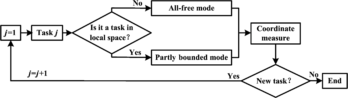
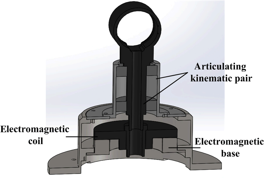
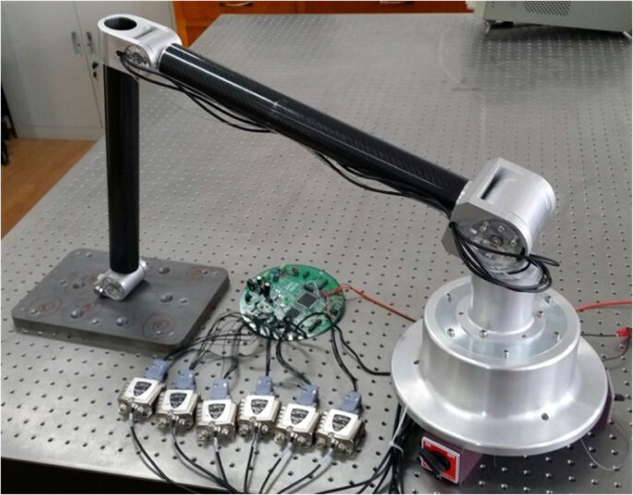
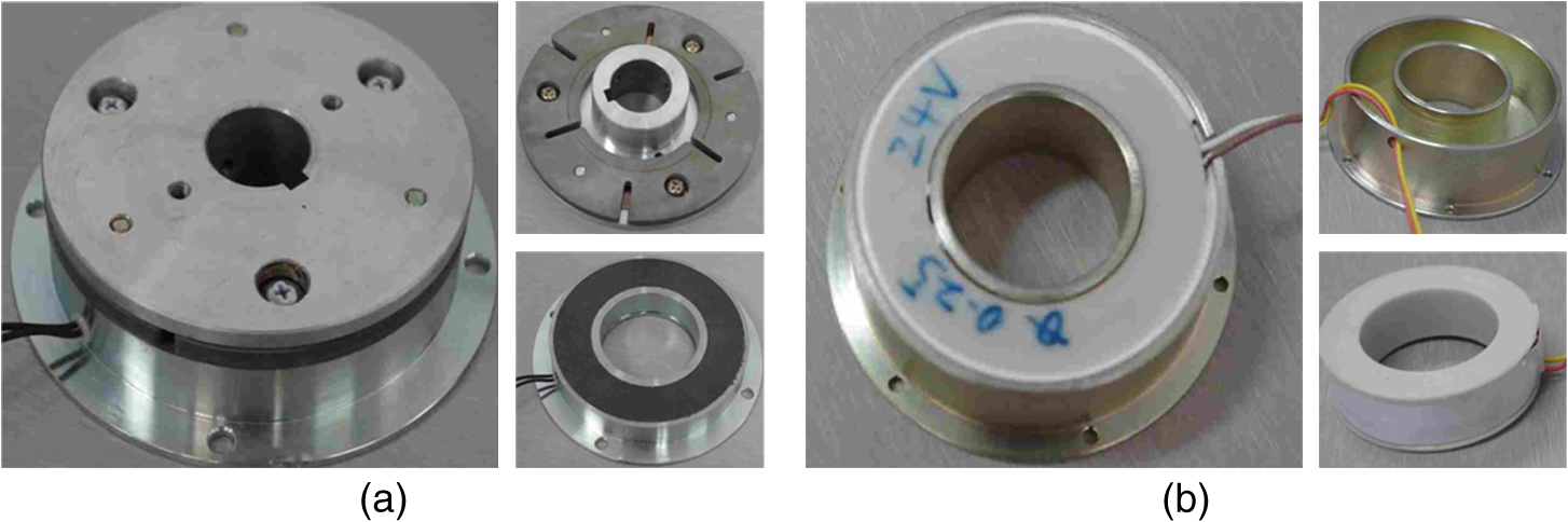
1.IntroductionThe coordinate measuring machine has been applied extensively as a key precise tool for guaranteeing product quality in the automobile and ship manufacturing industries.1,2 Although the traditional orthogonal coordinate measuring machine has high measurement precision, its usage in onsite applications is extremely limited by its complex structure, high cost, and strict ambient demands. Because of this, the nonorthogonal coordinate measuring machine has made rapid developments in the last two decades. For example, the flexible articulated arm coordinate measuring machine (AACMM), characterized with simple structure, low cost, and portability, has been broadly applied in those industries that have a low measurement precision requirement.3–6 The articulated arm coordinate measuring machine is designed as a serial, spatial, open-linked structure. It usually consists of three arms and six articulations and can move freely in multiple degrees of freedom. The error of every arm and articulation will be accumulated and transmitted step-by-step toward the end in an amplificatory way. For years, the measurement precision has impeded further application of the AACMM. Researchers as well as manufacturers have carried out various works in the hierarchies of system structure design and system model calibration. In the former, the tolerances of elements and assemblies have been improved. In the latter, different calibration methods have also been developed for better precision.7–9 Hamana et al. proposed a calibration method for the kinematic parameters of the AACMM using spherical center coordinates. Santolaria et al. presented a new technique for capturing data that allows the subsequent identification of the AACMM kinematic parameters and a new repeatability error measurement correction method based on Fourier polynomials. Sładek et al. proposed a description of modeling and the identification of errors of the AACMM based on a metrological model. In addition to the pursuit of improvement in structure design and model calibration, we pay attention to the real operation situation. Although the AACMM has a large measurement space, most measurement tasks in real applications are limited in a local space, where some, but not all, of the arms and articulations are needed to move. In those cases, decreasing the system’s degrees of freedom of motion obviously can reduce the importation of errors and improve the measurement precision significantly. From this point of view, the contribution of this paper is not to make an improvement in structural design or model calibration, but to break the current measurement mode of the AACMM. A new coordinate measuring method based on the adjustable articulated arms for the AACMM in two operation modes is proposed. This measurement method will maintain the measurement capability in global space and improve the measurement precision in local space. 2.Adjustable Strategy and Implementation2.1.Adjustable StrategyThe authors’ previous studies showed that the front articulations generally have a greater impact on the measurement precision.10,11 Thus, if one front articulation is locked, the front articulation error is not imported to the measurement, and the precision may be improved. This paper presents a coordinate measuring method based on the adjustable articulated arms. The word “adjustable” means the AACMM has two operation modes: one with all-free articulated arms to maintain coordinate measurement ability in global space (which is the traditional coordinate measurement) and the other with partially bound articulated arms, achieved by locking the first two articulations to improve the coordinate measurement precision in the local space. In the meanwhile, the adjustable articulated arms could automatically switch between the above two operation modes. Figure 1 shows the operation scheme of the adjustable AACMM. The locking device, whose essence is to lock the rotating articulation of the arms, is the key to the adjustable AACMM. This paper develops an electromagnetic locking device, which can precisely and automatically lock and unlock the articulation at any position. As shown in Fig. 2, the locking device consists of an electromagnetic base and an electromagnetic coil. They are fixed with two sides of one articulation kinematic pair. When the locking device is powered off, there is no constraint between the base and the coil, so the articulating kinematic pair can move freely. When the locking device is powered on, a force constraint is placed between the base and the coil, and the articulating kinematic pair will be locked firmly. The force of the device can be increased by increasing the coil turns to meet the maximum force required. Most importantly, the locking device can be controlled to realize the automatic switch between the all-free articulated arms operation mode and the partially bound articulated arms operation mode. 2.2.Adjustable Measurement SystemFigure 3 shows an adjustable AACMM with the electromagnetic locking device designed and developed in this paper. The prototype consists of a base, three arms, six articulations, two locking devices, and a probe. The two locking devices are placed in articulations 1 and 2, respectively. Articulated arm 1 and the base, as the supports of the other parts of the prototype, are made in the shape of barrel by 40Cr steel to reduce distortion. Articulated arms 2 and 3, which are supposed to move in any direction, are made in the shape of thin barrel by carbon fiber to reduce weight. The neighborhood articulated arms are connected with double cross-articulations, as shown in Fig. 4(a). The cross-articulations can rotate along two vertical directions independently. Every articulation is equipped with a circular grating angle sensor to measure the articulation angle. Figure 4(b) shows the M1800 angle sensor from MicroE, Bedford, Massachusetts installed on the surface of the articulation bearing. The locking devices, shown in Fig. 5, have been developed taking into consideration the structures and the force requirements of articulations 1 and 2. 3.Adjustable Mathematical ModelThe adjustable AACMM consists of three arms, six articulations, and two locking devices. Figure 6 shows the structure and coordinate frames of the adjustable AACMM. {} is the base coordinate frame and {} is the probe coordinate frame {}. () is the articulation coordinate frame defined at each articulation. Fig. 6Structure and coordinate frames of the adjustable articulated arm coordinate measuring machine (AACMM). 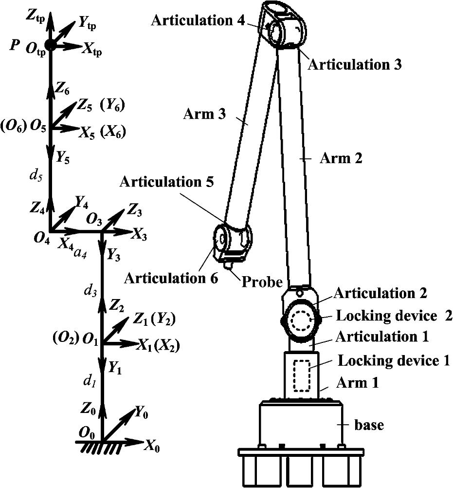 The D–H model, proposed by Denavit and Hartenberg, is used in the mathematical modeling of the adjustable AACMM.12 There are four types of structure parameters in the D–H model: (1) arm length is the distance between adjacent rod length between the -axis; (2) articulation length is the distance between the adjacent Z-axis; (3) twist angle is the angle between the adjacent -axis with the right hand around the X-axis as the positive; and (4) articulation angle is the angle between the adjacent -axis with the right hand around the -axis as the positive. According to the D–H method, the homogeneous transformation matrix from {} to the coordinate system {} () is Let the homogeneous coordinates of the probe in the sixth articulation coordinate frame {} be and the homogeneous coordinates in the base coordinate frame {} be . The mathematical measurement model for the adjustable AACMM is In the partially bound articulation arms operation mode, articulations 1 and 2 ( and ) are fixed, while the other four () can rotate freely. In the all-free articulation arms operation mode, all six articulations can move freely and can change freely. Therefore, the all-free AACMM has a set of structural parameters , and a set of extrinsic parameters , . But the partially bound AACMM has a set of structural parameters , and a set of extrinsic parameters , . Both operation modes and their parameter sets construct the adjustable AACMM and its mathematical model. 4.Analysis and Test4.1.Measurement Precision AnalysisThe measurement precision of the AACMM is affected by many factors, such as parameter error and environmental error. The parameter error is one of the most important errors, mainly produced in the machining and assembly process. The four types of parameters in the transformation matrix of the D–H model have great influence on the measurement precision. According to the structure and extrinsic parameters of the all-free AACMM, the measurement error of the probe can be denoted as In the same way, the measurement error of the probe for the partially bound AACMM can be denoted as Although these two AACMM operation modes have different model parameters, they have the same model equation. So, after system calibration, the same model parameters could be supposed to have equal errors theoretically, meaning for , , , and for . Due to structural design and assembly error, there is an articulation angle error between the indication and true angle. As the extrinsic parameters, the same articulation angles of the two AACMM operation modes should have the equal errors for . Therefore, the difference of the measurement error between these two operation modes is Parameter calibration is aimed at true value, so the error after calibration should be less than the error before calibration. Thus, the articulation angles as the structure parameters are clearly more accurate than the ones as the extrinsic parameters, and , , and . Therefore, in theory, the measurement error of the partially bound AACMM should be less than the one of the all-free AACMM. That is to say, the partially bound AACMM operated in the local space could improve the measurement precision. 4.2.Measurement Precision TestTo illustrate the improvement in precision from the all-free AACMM to the partially bound AACMM, precision tests for single point repeatability and length measurement precision are performed through numerical simulation. Under the partially bound operation mode, articulations 1 and 2 are fixed at the angles of 0 and , respectively. Under the all-free operation mode, all six articulations can rotate freely. Table 1 shows the parameters and their errors to be set in simulation. A set of 88 points are tested under these two modes, respectively, and each point is measured by 50 different sets of articulation orientations. As shown in Fig. 7, these 88 points lie in a local space of . Table 1Simulation parameters and their errors of the adjustable AACMM.
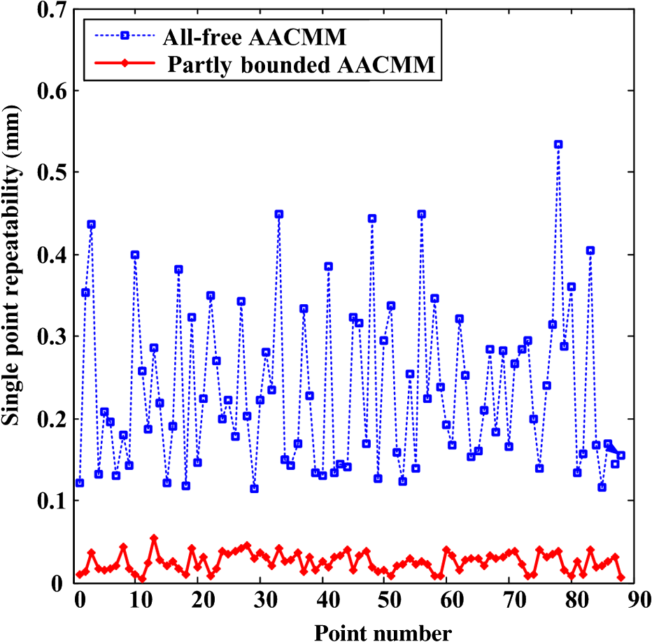
4.2.1.Single point repeatability testAfter the adjustable AACMM is calibrated by the method presented in Ref. 13, the single point repeatability of each test point is defined as For our work, is equal to 50. Figure 8 shows the single point repeatability errors of the 88 points calculated based on the calibrated partially bound and all-free AACMM. The maximum single point repeatability of the all-free AACMM is 0.5342 mm, while the maximum single point repeatability of the partially bound AACMM is 0.0541 mm. Therefore, the single point repeatability of the partially bound AACMM is improved by about 10 times that of the all-free AACMM in the local space. 4.2.2.Length measurement precision testCentering on the distance between any two points of the above 88 points, the length measurement error is defined as where is the distance between two points by the ’th measurement, is the true value distance between these two points, and . The length test performed over the 3828 distances of the 88 points in the local space shows that the maximum length measurement error of the all-free and partially bound AACMM is 0.6387 and 0.0908 mm, respectively. Figure 9 shows the length measurement error under the two modes of the adjustable AACMM for any 100 distances chosen from the 3828 distances. The length measurement precision of the partially bound AACMM is improved by about seven times compared to that of the all-free AACMM in the local space. Additionally, the length measurement error of the longer distance is not meant to be bigger. According to previous research,10,11 the distribution of the length error in the AACMM is nonlinear and related to the articulation orientation.5.ConclusionIn this paper, a coordinate measuring method with two operation modes based on the adjustable articulated arms is proposed. The adjustable AACMM with two electromagnetic locking devices can automatically switch between the all-free articulated arms and the partially bound articulated arms operation mode. In the all-free articulated arms mode, three arms and six articulations can rotate freely in global space. In the partially bound articulated arms mode, the front two articulations are locked to decrease the import of angle errors. A mathematical model for the adjustable AACMM is also built in this paper. Theoretical analysis and numerical simulation show that the partially bound articulated arm coordinate measuring machine is more precise than the all-free one in the local space. Therefore, the proposed coordinate measuring method based on the adjustable articulated arms is verified as being effective. Future work will be conducted on the calibration and real measurement applications of this prototype. AcknowledgmentsThis work was supported by the National Natural Science Foundation of PR China (Grant Nos. 51075038 and 51375057), the General Program of Science and Technology Project of Beijing Municipal Education Commission (No. KM201411232004), and the Program for Changjiang Scholars and Innovative Research Team in University of IRT1212. ReferencesJ. A. Bosch, Coordinate Measuring Machines and Systems, Marcel Dekker, Inc., New York
(1995). Google Scholar
G.-x. Zhang,
“Development orientations of coordinate measuring techniques [In Chinese],”
Infrared Laser Eng., 37
(S), 1
–5
(2008). 1007-2276 Google Scholar
B. Monsarratet al.,
“Workspace analysis and optimal design of a 3-leg 6-DOF parallel platform mechanism,”
IEEE Trans. Rob. Autom., 19
(6), 954
–996
(2003). http://dx.doi.org/10.1109/TRA.2003.819603 IRAUEZ 1042-296X Google Scholar
K. Furutaniet al.,
“Multiple degrees-of-freedom arm with passive joints for on-the-machine measurement system by calibrating with geometric solids,”
Precis. Eng., 23
(2), 113
–125
(1999). http://dx.doi.org/10.1016/S0141-6359(99)00003-3 PREGDL 0141-6359 Google Scholar
P. CarboneD. MaciiD. Petri,
“Measurement uncertainty and metrological confirmation in quality-oriented organizations,”
Measurement, 34
(4), 263
–271
(2003). http://dx.doi.org/10.1016/j.measurement.2003.07.003 MSRMDA 0263-2241 Google Scholar
W. GaoS. KiyonoE. Satoh,
“Precision measurement of multi-degree-of-freedom spindle errors using two-dimensional slope sensors,”
Ann. CIRP, 51
(1), 447
–450
(2002). http://dx.doi.org/10.1016/S0007-8506(07)61557-1 CIRAAT 0007-8506 Google Scholar
H. Hamanaet al.,
“Calibration of articulated arm coordinate measuring machine considering measuring posture,”
Int. J. Autom. Technol., 5
(2), 109
–114
(2011). 1229-9138 Google Scholar
J. Santolariaet al.,
“Kinematic parameter estimation technique for calibration and repeatability improvement of articulated arm coordinate measuring machines,”
Precis. Eng., 32
(4), 251
–268
(2008). http://dx.doi.org/10.1016/j.precisioneng.2007.09.002 PREGDL 0141-6359 Google Scholar
J. SładekK. OstrowskaA. Gąska,
“Modeling and identification of errors of coordinate measuring arms with the use of a metrological model,”
Measurement, 46
(1), 667
–679
(2013). http://dx.doi.org/10.1016/j.measurement.2012.08.026 MSRMDA 0263-2241 Google Scholar
C. Yajunet al.,
“Study on error of initial position of multi-joint coordinate measuring machine [In Chinese],”
Tool Eng., 46
(7), 76
–79
(2012). Google Scholar
J. Xuet al.,
“The simulation research of the joint angles error of articulated arm coordinate measuring machine [In Chinese],”
Manuf. Technol. Mach. Tool, 4 72
–76
(2013). Google Scholar
J. DenavitR. S. Hartenberg,
“A kinematic notation for lower-pair mechanism based on matrices,”
Trans. ASME J. Appl. Mech., 77 215
–221
(1955). JAMCAV 0021-8936 Google Scholar
L. Zhuet al.,
“Research on parameter self-calibration method for partly-bonded articulated arm coordinate measuring machine,”
Chin. J. Sci. Instrum., 35
(3), 572
–579
(2014). YYXUDY 0254-3087 Google Scholar
BiographyLianqing Zhu received his master’s degree of control science and engineering in HeFei University of Technology in 1989 and earned his PhD degree in Harbin Institute of Technology in 2012. Now, he is a professor at the Beijing Information Science and Technology University. His main research interests focus on biological medicine inspection technology and instrument, precise optical-electrical test technology, and so on. Weixian Li received her bachelor’s degree and PhD degree of precision instrument and machinery in Beihang University in 2007 and 2013, respectively. Now, she is a lecturer at Beijing Information Science and Technology University. Her main research interests focus on machine vision, optical-electrical test technology, and so on. Zhikang Pan received his master’s degree in technology and instrument measurement from Beijing Institute of Technology in 2003, and now he is a lecturer at Beijing Information Science and Technology University. His main research interests focus on precise optical-electrical test technology. Yangkuan Guo received his PhD degree of instrument science and technology in Tsinghua University in 2005. Now, he is a professor at Beijing Information Science and Technology University. His main research interests focus on precise optical-electrical test technology and so on. Qingshan Chen received his PhD degree of physical electronics from Beijing University of Posts and Telecommunications in 2009. Now, he is a senior engineer at Beijing Information Science and Technology University. His main research interests focus on precise optical-electrical test technology and so on. |
|||||||||||||||||||||||||||||||||||||||||||||||||||||||||||||||||||||||||||||