|
|
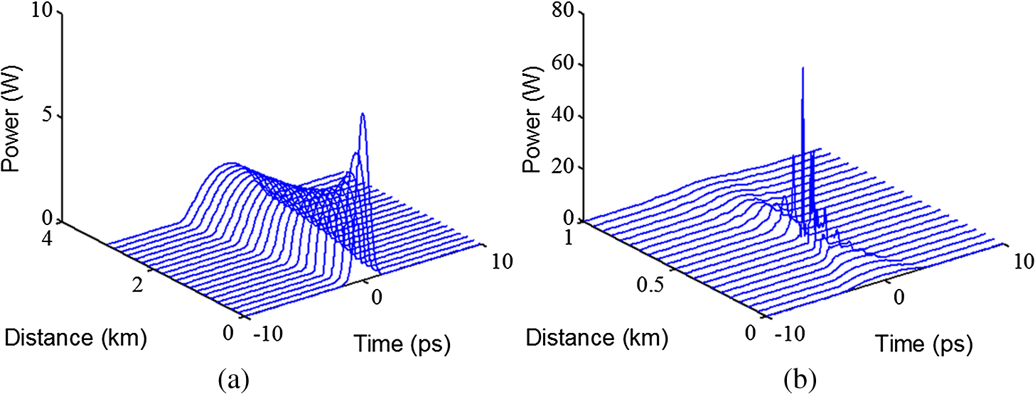
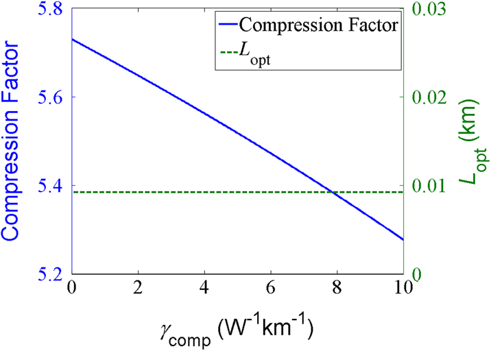
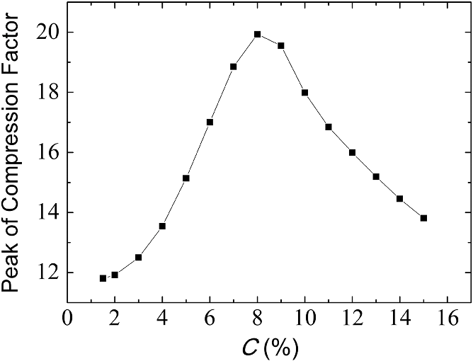
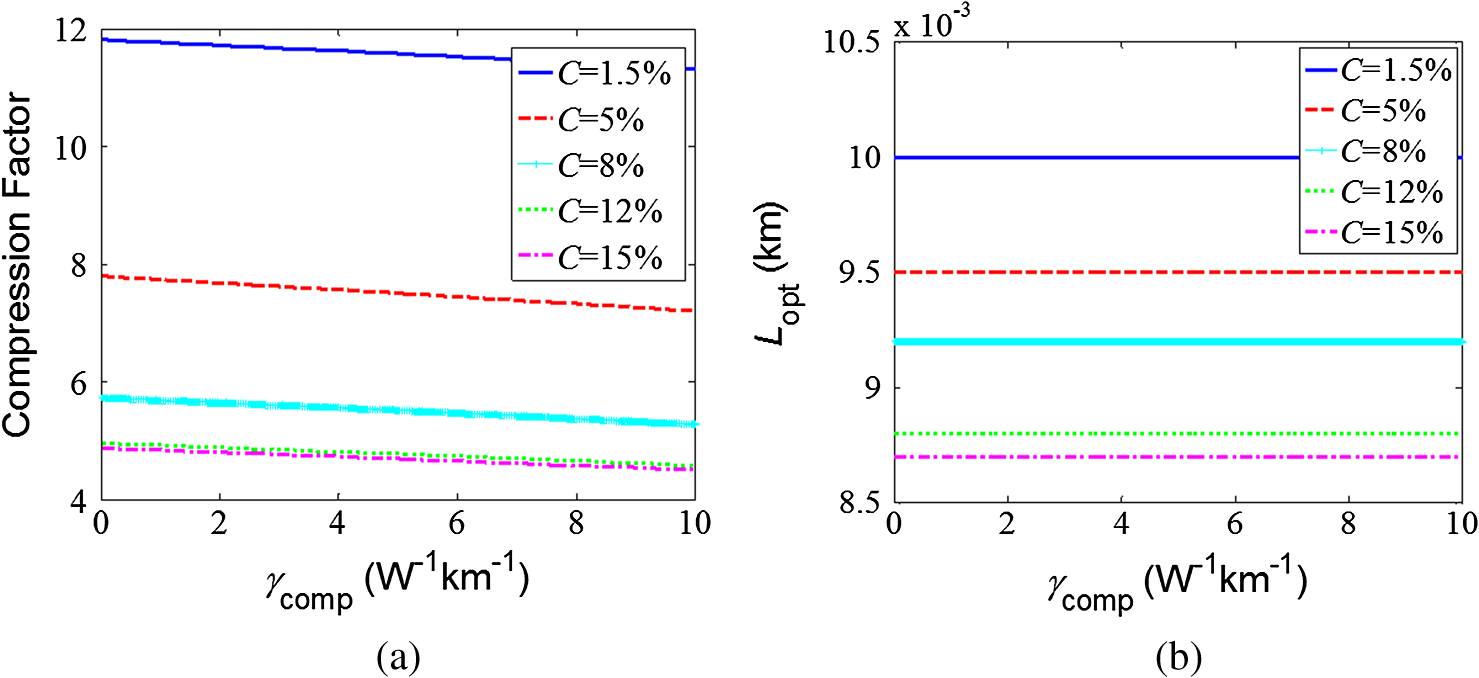
1.IntroductionParabolic similariton (self-similar pulse) in normal dispersion nonlinear fibers or high-power fiber amplifiers has been widely studied over recent years. It is brought about by the combined effect of normal group-velocity dispersion (GVD), self-phase modulation, and gain. The similariton pulse represents a particular class of solution for the nonlinear Schrödinger equation (NLSE) with gain and has some attractive characteristics, such as maintenance of a parabolic intensity profile, resistance to optical wave breaking, and a highly linear chirp.1–3 These attractive features lead a self-similar pulse to a number of applications including similariton lasers,4–6 optical pulse synthesis,7 and generation of high-repetition-rate parabolic pulse trains associated with telecommunications systems.8,9 In particular, a highly linear chirp of similariton leads to efficient pulse compression to the femtosecond domain.10–13 A rare-earth-doped fiber amplifier12,14–16 and a Raman fiber amplifier17 have been used to generate a high-energy parabolic similariton, but amplification requires a high power pump source and hence adds cost and complexity to the system. Passive fibers such as dispersion-decreasing fiber (DDF),18–20 comb-like dispersion profiled fiber,21 and nonlinearity increasing fiber22,23 can all be equivalent to a constant dispersion fiber with gain, so they are connected with self-similar pulse shaping and pulse compression to meet the requirements of a telecommunication systems and small commercial systems. Another passive method is a two-stage fiber device demonstrated by Finot et al. in numerical and experimental ways. The first fiber in this device is used to generate linearly chirped parabolic pulses by carefully choosing the initial power and the length of the fiber, whereas the second fiber is used to stabilize the parabolic pulse by abruptly increasing linearity and decreasing dispersion.24 This method has been successfully applied to the generation of high repetition 40-GHz picosecond parabolic pulse trains.25 A parabolic pulse in self-similar regime represents a strict linear chirp across the pulse, so it can be compressed by passing it through a linear dispersive medium with anomalous GVD. Such a medium imposes a GVD-induced linear chirp on the pulse so that this negative chirp can cancel the linear, positive chirp of the input parabolic pulse, resulting in an output pulse that is narrower than the input pulse. Since the GVD-induced chirp is linear across the entire pulse width, the linear chirp of the parabolic pulse should cover as wide a temporal range as possible in order to get optimal chirp cancelation. Thus, the degree of self-similar evolution has an important influence on the quality of the compressed pulse. A pair of two parallel gratings acts as a dispersive delay line. Optical pulses propagating through such a grating pair behave as if they were transmitted through an optical fiber with anomalous GVD, so the combination of a positive dispersion fiber with gain and a grating pair can be taken as a pulse compressor.26 The fiber link consists of two segments of fibers, in which the dispersion has opposite signs. One can achieve the same result by using a positive dispersion fiber with gain to generate a self-similar pulse and a negative dispersion fiber to achieve pulse compression.27 The grating pair or the negative dispersion fiber acts as a compensative fiber here. Compared to active self-similar pulse compressors which are connected to a fiber amplifier, such passive fiber compressors are more suitable for optical fiber communication systems due to their simplicity and low cost. Recently, there have been more and more studies on the propagation characteristics of a similariton28,29 and self-similar compression effects.30 However, these researches are more concerned with active compression effects connected with fiber amplifiers. To date, there are still limited studies on the compression characteristics and parameter optimization of passive self-similar compressors. Especially, the influences of compensative fiber parameters on compression effects have never been considered before. The generation method based on DDF is a well-developed passive method and it has been widely used for its simplicity and stability,31 so we present in this paper a passive self-similar compressor consisting of a DDF and a compensative fiber. Here, a DDF is used to generate a self-similar pulse, whereas the compensative fiber with anomalous GVD is used to cancel the chirp so that the pulse is compressed. By using the split-step Fourier method, we numerically study the influences of compensative fiber parameters and self-similar evolution degree on (i) compression factor and peak power of the compressed pulse, and (ii) optimal length of compensative fiber. Our results offer some theory evidences about the optimization design of self-similar compressors. 2.Generation of Self-Similar Pulse and Shaping of Compressed Pulse in Dispersion-Decreasing Fiber Type Self-Similar CompressorPulse propagation in a DDF with positive GVD can be modeled by the NLSE when fiber losses, high-order dispersion, and high-order nonlinear effects are neglected: Here, is the slowly varying amplitude of the pulse envelope and is the time in a copropagating time-frame. is the GVD parameter at and is the nonlinear parameter. represents the hyperbolic decrease of the GVD profile with distance and is normalized as , where is the gain coefficient. Fiber losses and high-order effects are neglected here to make the results in the following sections clearer and easier to distinguish. The solution of Eq. (1) has been proven to be a self-similar asymptotic solution, characterized by a parabolic intensity profile:18 with where is the energy of the initial pulse and is an arbitrary constant. The linear chirp of the pulse is of the formSuch a positive linear chirp can be cancelled by the GVD-induced chirp of a linear dispersive medium with an anomalous GVD. Thus, by launching the output pulse from DDF into a compensative fiber, we can obtain an ultrashort pulse. The combination of the DDF and compensative fiber can be called a DDF type self-similar compressor. To describe this compression process, we plot the evolution of the Gaussian pulse in a 3-km DDF in Fig. 1(a) and the following evolution of this pulse in a 1-km compensative fiber in Fig. 1(b). The input Gaussian pulse has initial energy and initial pulse width (i.e., the half-width at -intensity point) . The DDF has a dispersion of at and a nonlinearity of and a gain coefficient , whereas the compensative fiber has an opposite GVD of and a nonlinearity of . As we can see, the Gaussian pulse evolves to a parabolic profile asymptotically as the propagation distance increases in the DDF. When this parabolic pulse enters the negative dispersion regime in the compensative fiber, pulse width tends to narrow down with an increasing intensity. This trend is maintained until a complete chirp cancelation occurs at a distance called the optimal compensative fiber length , where a best compressed pulse with the highest intensity is generated. Beyond this distance, the degree of chirp compensation is reduced and the net chirp begins to increase, again leading to pulse broadening. The degree of pulse compression can be described by a compression factor defined as , where and are the root-mean-square width of the incident pulse and output optimal compressed pulse of the compressor, respectively. 3.Influences of Compensative Fiber Parameters on Pulse Compression CharacteristicsTo study the influence of the GVD parameter of the compensative fiber on compression characteristics in a DDF type self-similar compressor, we launch a Gaussian pulse into a 6.9-km-long DDF and then compress the output parabolic pulse in a 1-km-long compensative fiber. The GVD parameters range from 0 to , while other fiber parameters and the parameters of the incident Gaussian pulse are the same as in Fig. 1. Figure 2(a) represents the variation of the compression factor and optimal compressed pulse peak power with , whereas Fig. 2(b) gives the variation of the optimal compensative fiber length with . Fig. 2(a) Compression factor and peak power of optimal compressed pulse versus group-velocity dispersion (GVD) parameter of compensative fiber. (b) Optimal compensative fiber length versus GVD parameter of compensative fiber. 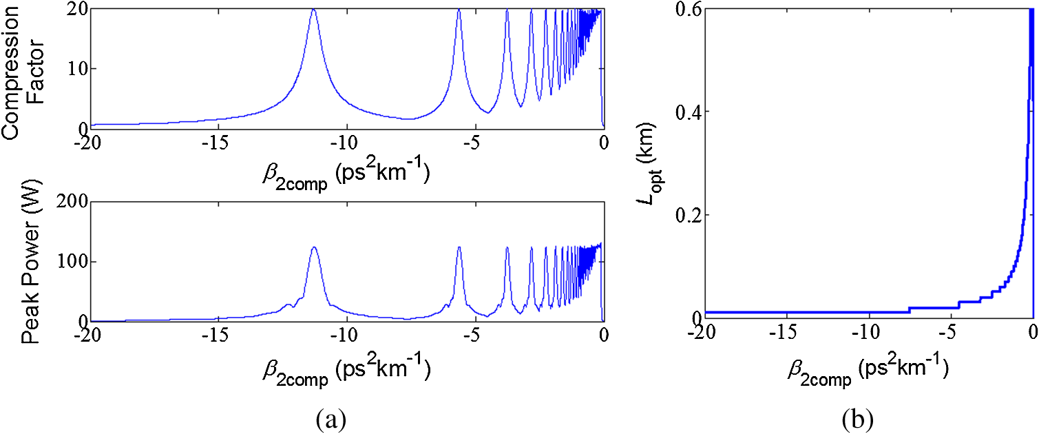 As we can see in Fig. 2(a), the compression factor and peak power of the optimal compressed pulse vary periodically with , and the period interval increases with the absolute value of . The compression factor and peak power have almost the same peak value in every period, which indicates that the pulse compression has a limit. Given the parameters of DDF in the compressor, we can choose a proper to get the narrowest limit of the pulse width after chirp compensation. In this way, the compression factor and peak power of the compressed pulse both reach a maximum, which means a compressed pulse with the best quality is obtained. From an energy point of view, energy is concentrated, then dispersed, and then concentrated again periodically with the variations of . Such energy transfer in half a period can be described by Fig. 3. The solid, dotted, dashed, and dash-dotted curves correspond to four intensity profiles of the optimal compensative pulse inside a period from peak to trough in Fig. 2(a), where the corresponding are , , , and , respectively. It is thus clear that at a peak in Fig. 2(a) (), the best compressed pulse has the narrowest width and the highest peak power, which shows the energy of the optimal compensative pulse is most concentrated there. After leaving the peak, pulse energy is gradually transferred to the wings, the pulse broadens and the compression factor decreases. These trends go on until a trough in Fig. 2(a) appears (), after which the energy is transferred from the wings to the pulse center again, and the pulse is compressed with a better profile. Moreover, increasing the absolute value of will extend the period of energy transfer as well as reduce the trough of the compression factor and peak power in each period [see Fig. 2(a)], which illustrates that the larger value of will cause more energy transfer between the pulse center and the wings in a single period. When the value of becomes relatively large, the compression factor near the trough in Fig. 2(a) will even be less than 1, which indicates that the compression effect may fail, even at the optimal compensation point. Fig. 3Output pulses optimally compensated by different GVD parameters of compensative fiber for an initial DDF. The solid curve, dotted curve, dashed curve, and dash-dotted curve represent the intensity profiles of the optimal compressed pulse when GVD parameters of the compensative fiber are , , , and , respectively. The energy transfer between the peak and the trough in a period corresponding to Fig. 2(a) is described. 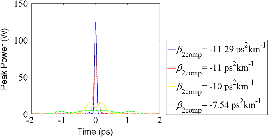 The relatively small compression factor near the origin in Fig. 2(a) and its sharp increase are because the length of the compensative fiber is limited in our simulations. When is close to zero, complete chirp cancelation needs a much longer compensative fiber so the narrowest pulse represents the output pulse of the 1-km compensative fiber. The consequent compression factor is small and then rapidly increases with the value of due to the increasing compensation effect. Figure 2(b) shows the relation between the optimal compensative fiber length and only within a 0.6-km compensative length. As expected, when the value of increases, first decreases rapidly and then changes slowly until it tends to be flat. This result can be interpreted by the dispersion compensation theory: In the case where the amount of compensation is the same, a larger value of dispersion means a faster compensation so that a shorter length is needed to complete chirp cancellation. The nonlinearity of the compensative fiber is a disadvantage to the quality of a self-similar-compressed pulse. Simulations show that the large nonlinear effect in a compensative fiber will cause serious damage to the quality of the compressed pulse. We discuss such an influence caused by nonlinear parameters of the compensative fiber when they range from 0 to . The results are shown in Fig. 4 which illustrates how the compression factor and vary with . The parameters of the DDF and the incident Gaussian pulse are the same as in Fig. 2, and the 1-km-long compensative fiber has a dispersion of . It is thus clear that the compression factor is a decreasing function of , which shows that increasing the nonlinearity of the compensative fiber will broaden the optimal compressed pulse and cause a loss of compressed pulse quality as well. On the other hand, a large, negative dispersion in a compensative fiber rapidly compensates for the positive linear chirp of the self-similar pulse so is only 9.2 m. As we expected, the compression effect is caused by the cancellation of dispersion with opposite signs so that is not related to , as we see in Fig. 4. 4.Influence of Self-Similar Evolution Degree on Pulse Compression CharacteristicsA self-similar coefficient is introduced here to describe the evolution degree of the self-similar pulse in the DDF: where and represent the numerical solution and parabolic asymptotic solution of the output amplitude, respectively. The output pulse of the DDF evolves more completely and is more similar to the parabolic profile with a smaller . When the propagation distance satisfies , the output pulse of the DDF exhibits obvious self-similar features and thus enters a self-similar region, which implies complete evolution of the similariton without obvious oscillations.31 The following discussions are limited to the effective self-similar region before nonlinear oscillations. Figure 5 shows a plot of as a function of the propagation distance in the DDF when the propagating pulse starts to enter a self-similar region. With an increase of propagation distance, decreases, which implies a greater self-similar evolution degree, so that a higher quality self-similar pulse can be obtained by increasing the length of the DDF within this range.Fig. 5Dependence of self-similar coefficient on propagation distance at the start of self-similar region in DDF. 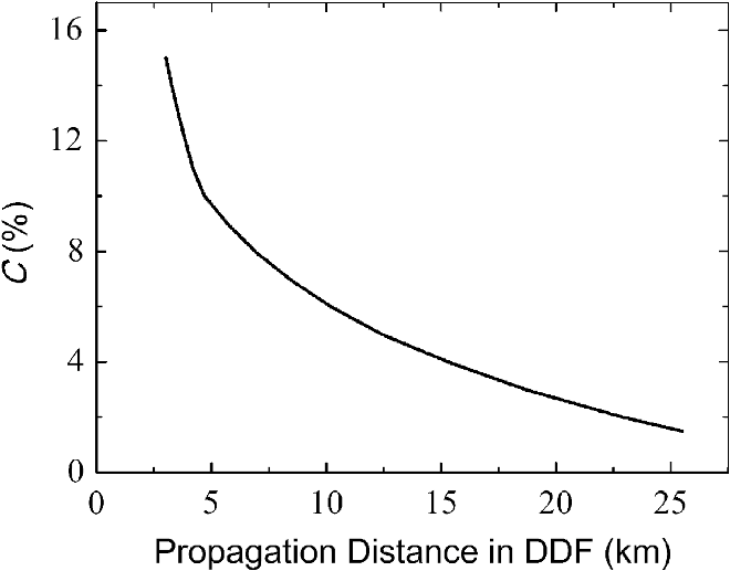 To consider the influence of the self-similar evolution degree measured by , we show in Fig. 6 the influence of on the compression factor and optimal compressed pulse peak power with different values of . The parameters of the fibers and the incident Gaussian pulse are the same as in Fig. 2, except that the DDF lengths are 3.02, 3.86, 6.9, 12.4, and 25.5 km, respectively, corresponding to , 12%, 8%, 5%, and 1.5%, respectively. It is interesting to see that when decreases, which means the propagation distance increases, the period interval that the compression factor and peak power vary with increases, while the trough inside each period decreases. That is to say, a greater evolution degree of self-similar pulse will cause a longer energy transfer period and more energy transfer between the pulse center and the wings. In addition, the peak of the compression factor and peak power inside each period first increases and then decreases with the decrease of . This is because when decreases, on one hand the parabolic pulse evolves more completely and then the linear chirp covers a wider temporal range of the pulse, which leads to a more complete chirp cancelation and an ultrashort pulse with higher energy. On the other hand, an increase of the DDF length will broaden the output self-similar pulse of the DDF and reduce its power, thus the overall compression ratio of the self-similar compressor and the peak power of output-compressed pulse tend to decrease. Therefore, a suitable degree of self-similar evolution helps to obtain the maximum compression limit at which the peaks of the compression factor and peak power in Fig. 6 attain their highest values. We find the optimal value of to be 8% in Fig. 6. Fig. 6Compression factor and peak power of optimal compressed pulse versus GVD parameter of compensative fiber with different self-similar coefficients. 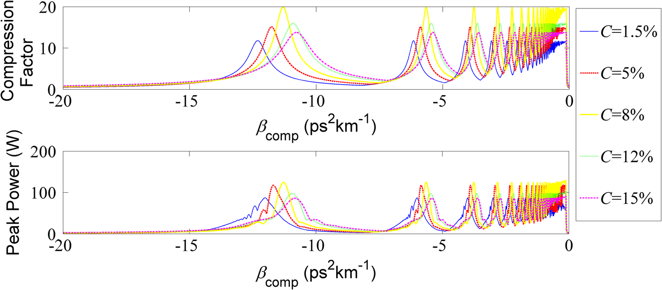 Figure 7 further discloses the relation between the peak value of the compression factor in Fig. 6 and . It is thus clear that the peak value of the compression factor has a maximum when , corresponding to a 6.9-km-DDF length. A longer DDF or a smaller C improves the self-similar evolution degree of similariton, but also decreases final compression ratio of the compressor due to the excessive broadening and too low power of the similariton. The relation between the peak value of the peak power in Fig. 6 and is similar to Fig. 7 for the same mechanism. Finally, we show in Fig. 8(a) the variation of the compression factor with when , 12%, 8%, 5%, and 1.5%, respectively. The corresponding DDF lengths are the same as in Fig. 6. The dispersion of the compensative fiber is , corresponding to one of the peaks of the compression factor when in Fig. 6. Other parameters of the fibers and the incident Gaussian pulse are the same as in Fig. 4. The changing trend in Fig. 8(a) can be interpreted by Fig. 6 by noting that with the increase of , the compression factor decreases when . So, the same trend appears in Fig. 8(a). Moreover, our simulation results show that the optimal compensative fiber length is a decreasing function of [see Fig. 8(b)]. This is because when decreases, the DDF length increases and then the amount of compensation becomes greater, which leads to a longer compensative distance. 5.Parameter Optimization of Dispersion-Decreasing Fiber Type Self-Similar CompressorFrom the discussion above, it can be seen that it is easy to obtain a high-energy, high-quality ultrashort pulse when the absolute value of is small due to the small fluctuations of the compression factor and optimal compressed pulse peak power of the compressor. In this case, however, the required length of the compensative fiber is long. If the length of the compensative fiber is limited, the periodic influence of on the compression factor and optimal compressed pulse peak power should be considered. For the parameters given above, the optimal DDF length is , corresponding to when the peaks of the compression factor and peak power in Fig. 6 reach a maximum. When this DDF length is selected, we take as , corresponding to one of the peaks of the compression factor when in Fig. 6. Here, the compensative fiber length required is only about 10 m. On the other hand, should be as small as possible because an increase of will decrease the compression factor. A suitable should be less than to get a high compression factor and peak power for the output pulse. When the parameters are optimized as , , and , the pulse width of the optimal compressed pulse is only 58 fs, the compression factor can reach 19.9, and the peak power of the compressed pulse is 126.0 W. 6.ConclusionsWe have numerically studied the compression characteristics of a DDF type self-similar compressor, which consists of a DDF and a compensative fiber with negative dispersion. Results show that the GVD parameter of the compensative fiber has a periodic influence on the compression factor and peak power of optimal compressed pulse. When the absolute value of increases, energy is periodically concentrated, then dispersed, and then concentrated again with an increasing interval. The compression limit can be reached or approached by choosing optimal values of at which compression factor reaches a maximum and the energy is most concentrated. Although it is easier to choose when its absolute value is small for the smaller fluctuations of the compression factor and peak power, in this case, the selection of an optimal should also consider the requirement of an optimal compensative fiber length. Since the optimal compensative fiber length decreases with , larger optimal values of can be selected in order to reduce the compensative length. On the other hand, the nonlinear parameter of compensative fiber has no effect on , but its increase drops the compression factor so that should be set to less than . Moreover, the increase of the DDF length will deepen the self-similar evolution degree of the parabolic similariton, but too long a DDF length will also cause excessive broadening to the similariton. Therefore, the DDF length has an optimal value and this optimal length is 6.9 km for our parameters given above. By optimizing the DDF length and the parameters of the compensative fiber, a high-quality compressed pulse can be obtained from the DDF type self-similar compressor. For the parameters given above, the narrowest pulse width after compression is 58 fs, and the compression factor and the optimal compressed pulse peak power of the compressor can reach 19.9 and about 130 W, respectively. Mastering these compression characteristics of a self-similar compressor is conducive to parameter optimization of the compressor, thus a high-energy ultrashort pulse can be obtained and the pulse compression limit can be reached. AcknowledgmentsThe authors thank two referees for many useful comments and suggestions. The work was supported by Innovation Personnel Training Plan for Excellent Youth of Guangdong University Project (Grant No. 2013LYM_0023). ReferencesM. E. Fermannet al.,
“Self-similar propagation and amplification of parabolic pulses in optical fibers,”
Phys. Rev. Lett., 84
(26), 6010
–6013
(2000). http://dx.doi.org/10.1103/PhysRevLett.84.6010 PRLTAO 0031-9007 Google Scholar
C. FinotG. MillotJ. M. Dudley,
“Asymptotic characteristics of parabolic similariton pulses in optical fiber amplifiers,”
Opt. Lett., 29
(21), 2533
–2535
(2004). http://dx.doi.org/10.1364/OL.29.002533 OPLEDP 0146-9592 Google Scholar
D. Andersonet al.,
“Wave-breaking-free pulses in nonlinear optical fibers,”
J. Opt. Soc. Amer. B, 10
(7), 1185
–1190
(1993). http://dx.doi.org/10.1364/JOSAB.10.001185 JOBPDE 0740-3224 Google Scholar
F. O. Ildayet al.,
“Self-similar evolution of parabolic pulse in a laser,”
Phys. Rev. Lett., 92
(21), 213902
(2004). http://dx.doi.org/10.1103/PhysRevLett.92.213902 PRLTAO 0031-9007 Google Scholar
B. Ortaçet al.,
“Self-similar low-noise femtosecond ytterbium-doped double-clad fiber laser,”
Appl. Phys. B, 85
(1), 63
–67
(2006). http://dx.doi.org/10.1007/s00340-006-2383-y APBOEM 0946-2171 Google Scholar
V. I. KruglovC. AguergarayJ. D. Harvey,
“Parabolic and hyper-Gaussian similaritons in fiber amplifiers and lasers with gain saturation,”
Opt. Express, 20
(8), 8741
–8754
(2012). http://dx.doi.org/10.1364/OE.20.008741 OPEXFF 1094-4087 Google Scholar
C. FinotG. Millot,
“Synthesis of optical pulses by use of similaritons,”
Opt. Express, 12
(21), 5104
–5109
(2004). http://dx.doi.org/10.1364/OPEX.12.005104 OPEXFF 1094-4087 Google Scholar
Y. Ozekiet al.,
“Generation of 10 GHz similariton pulse trains from 1.2 km-long erbium-doped fibre amplifier for application to multi-wavelength pulse sources,”
Electron. Lett., 40
(18), 1103
–1104
(2004). http://dx.doi.org/10.1049/el:20045277 ELLEAK 0013-5194 Google Scholar
C. FinotS. PitoisG. Millot,
“Regenerative wavelength converter based on similariton generation,”
Opt. Lett., 30
(14), 1776
–1778
(2005). http://dx.doi.org/10.1364/OL.30.001776 OPLEDP 0146-9592 Google Scholar
J. Limpertet al.,
“High-power femtosecond Yb-doped fiber amplifier,”
Opt. Express, 10
(14), 628
–638
(2002). http://dx.doi.org/10.1364/OE.10.000628 OPEXFF 1094-4087 Google Scholar
A. Malinowskiet al.,
“Ultrashort-pulse Yb3+-fiber-based laser and amplifier system producing average power,”
Opt. Lett., 29
(17), 2073
–2075
(2004). http://dx.doi.org/10.1364/OL.29.002073 OPLEDP 0146-9592 Google Scholar
C. Billetet al.,
“Intermediate asymptotic evolution and photonic bandgap fiber compression of optical similaritons around 1550 nm,”
Opt. Express, 13
(9), 3236
–3241
(2005). http://dx.doi.org/10.1364/OPEX.13.003236 OPEXFF 1094-4087 Google Scholar
A. Ruehlet al.,
“80 W, 120 fs Yb-fiber frequency comb,”
Opt. Lett., 35
(18), 3015
–3017
(2010). http://dx.doi.org/10.1364/OL.35.003015 OPLEDP 0146-9592 Google Scholar
V. I. Kruglovet al.,
“Self-similar propagation of high-power parabolic pulses in optical fiber amplifiers,”
Opt. Lett., 25
(24), 1753
–1755
(2000). http://dx.doi.org/10.1364/OL.25.001753 OPLEDP 0146-9592 Google Scholar
V. I. Kruglovet al.,
“Self-similar propagation of parabolic pulses in normal-dispersion fiber amplifiers,”
J. Opt. Soc. Am. B., 19
(3), 461
–469
(2002). http://dx.doi.org/10.1364/JOSAB.19.000461 JOBPDE 0740-3224 Google Scholar
V. I. KruglovA. C. PeacockJ. D. Harvey,
“Exact self-similar solutions of the generalized nonlinear Schrodinger equation with distributed coefficients,”
Phys. Rev. Lett., 90
(11), 113902
(2003). http://dx.doi.org/10.1103/PhysRevLett.90.113902 PRLTAO 0031-9007 Google Scholar
C. FinotG. Millot,
“Experimental generation of parabolic pulses via Raman amplification in optical fiber,”
Opt. Express, 11
(13), 1547
–1552
(2003). http://dx.doi.org/10.1364/OE.11.001547 OPEXFF 1094-4087 Google Scholar
T. HirookaM. Nakazawa,
“Parabolic pulse generation by use of a dispersion-decreasing fiber with normal group-velocity dispersion,”
Opt. Lett., 29
(5), 498
–500
(2004). http://dx.doi.org/10.1364/OL.29.000498 OPLEDP 0146-9592 Google Scholar
Q. F. ZhangJ. Gao,
“Generation of excellent self-similar pulses in a dispersion-decreasing fiber,”
Optik, 122
(19), 1753
–1756
(2011). http://dx.doi.org/10.1016/j.ijleo.2010.10.037 OTIKAJ 0030-4026 Google Scholar
Q. F. ZhangJ. Gao,
“Distortion of parabolic pulse due to higher-order effects in a dispersion-decreasing fiber,”
Optik, 123
(9), 823
–826
(2012). http://dx.doi.org/10.1016/j.ijleo.2011.06.046 OTIKAJ 0030-4026 Google Scholar
B. Kibleret al.,
“Parabolic pulse generation in comb-like profiled dispersion decreasing fiber,”
Electron. Lett., 42
(17), 965
–966
(2006). http://dx.doi.org/10.1049/el:20062073 ELLEAK 0013-5194 Google Scholar
H. T. ChenF. WangT. Deng,
“Study of the self-similar evolution for optical pulse in nonlinearity-increasing fibers,”
Laser Technol., 34
(2), 218
–220
(2010). Google Scholar
L. P. LiA. L. Zhang,
“Study on parabolic self-similar pulse generation in a nonlinearity increasing fiber,”
Chin. J. Lasers, 38
(8), 0805006
(2011). http://dx.doi.org/10.3788/CJL ZHJIDO 0258-7025 Google Scholar
C. Finotet al.,
“Parabolic pulse generation through passive nonlinear pulse reshaping in a normally dispersive two segment fiber device,”
Opt. Express, 15
(3), 852
–864
(2007). http://dx.doi.org/10.1364/OE.15.000852 OPEXFF 1094-4087 Google Scholar
C. Finotet al.,
“All-fibered high-quality low duty-cycle 20-GHz and 40-GHz picosecond pulse sources,”
IEEE Photonics Technol. Lett., 19
(21), 1711
–1713
(2007). http://dx.doi.org/10.1109/LPT.2007.906110 IPTLEL 1041-1135 Google Scholar
G. P. Agrawal, Applications of Nonlinear Fiber Optics, 3rd ed.Academic Press, San Diego
(2001). Google Scholar
Y. L. Liuet al.,
“Method of compression of parabolic self-similar pulses based on fiber link consisting of two segments of fibers,”
Acta Opt. Sin., 31
(5), 0519002
(2011). GUXUDC 0253-2239 Google Scholar
S. J. Wanget al.,
“Self-similar evolution in a short fiber amplifier through nonlinear pulse preshaping,”
Opt. Lett., 38
(3), 296
–298
(2013). http://dx.doi.org/10.1364/OL.38.000296 OPLEDP 0146-9592 Google Scholar
K. HammaniS. BoscoloC. Finot,
“Pulse transition to similaritons in normally dispersive fibre amplifiers,”
J. Opt., 15
(2), 025202
(2013). http://dx.doi.org/10.1088/2040-8978/15/2/025202 JOOPDB 0150-536X Google Scholar
J. S. Penget al.,
“All-fiber ultrashort similariton generation, amplification, and compression at telecommunication band,”
JOSA B, 29
(9), 2270
–2274
(2012). http://dx.doi.org/10.1364/JOSAB.29.002270 JOBPDE 0740-3224 Google Scholar
H. LüQ. F. ZhangX. Wu,
“Self-similar propagation region in passive optical fibers based on low-order approximation,”
Optik, 124
(18), 3335
–3339
(2013). http://dx.doi.org/10.1016/j.ijleo.2012.10.046 OTIKAJ 0030-4026 Google Scholar
BiographyHua Lü is a lecturer at Guangdong University of Technology. He received his BS and MS degrees in optics from South China University of Technology in 2002 and 2005, respectively. His current research interests include optical similartion, optical pulse compressor, and nonlinear optical communication. |