|
|
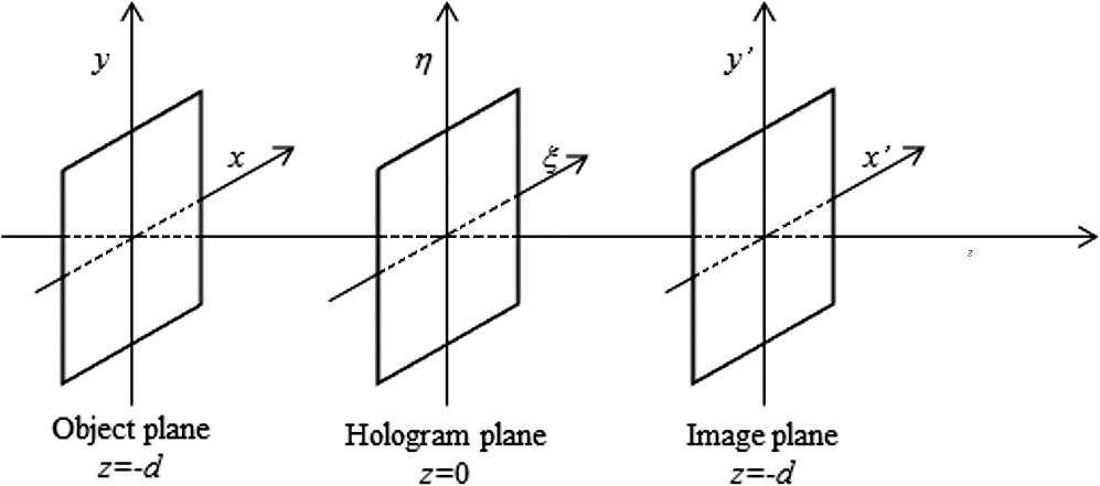
1.IntroductionThe microscope is one of the most useful tools for exploring and measuring the microscopic world, and its power quickly became clear to its discoverers. The microscope allows small objects to be imaged with very large magnifications. At the same time, it is clear that there is a trade-off: imaging very small objects brings a reduced depth of focus. That means that for higher magnification of the microscope objective, the corresponding in-focus imaged volume of the object is thinner along the optical axis. In fact, the microscope’s depth of field (DOF), depending on different conditions of use, is not sufficient to obtain a single image in which the whole longitudinal volume of the object is in-focus. If an accurate analysis of the whole object has to be performed, it is necessary to have a single sharp image in which all of the object’s details are still in focus, even if they are located at different planes along the longitudinal direction. Even when exploring an object having a three-dimensional (3-D) complex shape with high magnification, it is necessary to change the distance between the object and the microscope objective; doing so allows one to focus different portions of the object located on different image planes. Many scientists, using microscopes in different areas of research, are very aware of the intrinsic limitation of microscopes. In fact, in the community of microscopists, to have a single image with the necessary magnification but in which the entire object is in focus is highly desirable. This necessity has motivated many research efforts aimed at overcoming the aforementioned problems. Currently, the solution to this issue goes under the name of the extended focused image (EFI) and many solutions have been proposed. In traditional microscopy, EFI is composed by selecting different portions that are in sharp focus for each image, from a stack of numerous images recorded at different distances between the microscope objective and the objects.1–7 Modern microscopes are equipped with micrometric mechanical translators actuated by piezoelectric elements. The microscope objective is moved along the optical axis between the highest and lowest points of the objects with a desired and opportune number of steps. Essentially, what is performed is a mechanical scanning of the microscope to image the object at a discrete number of planes across all the volume it occupies. For each longitudinal step, an image is recorded and stored in a computer and linked with information of the depth at which it has been taken. The in-focus portion of each image is identified through some appropriate parameter, for example, the contrast measurement.2 Once these parts are identified, they are added to produce a composite EFI. In practice, the portion of the object from each image that appears to be or is numerically recognized as being in good focus is extracted by means of numerical algorithms.5,7 Then the different portions are composed together to give single images in which all details are in focus. In the EFI, all points of an object are in focus independent of their height in the topography of the object.6 Of course, the smaller the stepping increments that are performed in the mechanical scanning, the more accurate is the EFI result. On the negative side, the time taken for the acquisition increases with more steps and more calculation is needed to obtain the EFI. The time for for accurate and precise movements for single image acquisition over the entire programmed range essentially depends on the piezoactuator characteristic response time. Typically, it is difficult to have for acquisition of a single image. Even if the computing time is not a problem, the length of the acquisition process poses a severe limitation on obtaining an EFI for dynamic objects. An alternative investigated solution is based on the use of a specially designed phase plate to use in the optical path of the microscope. This allows a depth of focus extension in images observable by a microscope.8–12 The phase plate introduces aberrations on the incoming optical rays at the expense of some distortion and a blurring effect, but is capable of extending the depth of the focus. This method is called the wave front coding approach and has a severe drawback: a phase plate must be specifically designed and fabricated as a function of the object under investigation and of the adopted optical system. The important necessity of having an EFI can be satisfied, in principle, by holography. In fact, this technique has a unique attribute that allows recording and reconstruction of the amplitude and the phase of a coherent wave front that has been reflectively scattered or transmitted by an object through an interference process. The reconstruction process allows the entire volume to be imaged. Indeed, a very important advantage that is a result of using holography is that only one image has to be recorded. Subsequently, the whole volume can be scanned during the reconstruction process after the hologram has already been recorded. Furthermore, in this case, dynamic events can be studied and the EFI of a dynamic process can be obtained on the basis of using sequentially recorded holograms. In this work, techniques proposed over the years to overcome the limited DOF constraint of the holographic systems and to obtain a completely in-focus representation of the objects are discussed and compared. In Sec. 1, the theoretical principles of digital holography (DH) are briefly discussed, giving the readers an adequate background and a standardized knowledge of the symbology. In Sec. 2, the EFI construction methods are discussed. For the sake of simplicity, we divide them into two macro categories by application type. The first one involves methods used to reconstruct 3-D generic objects. This includes techniques inherited from traditional microscopy, such as the sectioning and merging approach, or multiplane imaging, which is to simultaneously visualize several layers within the imaged volume. Other approaches are also described, such as 3-D deconvolution methods that allow rebuilding of the true 3-D object distribution. The second macro area involves methods for objects recorded on a plane tilted with respect to hologram one. This case has raised great interest over the years, because its applications in several fields and many strategies have been proposed. Most strategies include the use of reconstruction techniques and rotation matrices, but the introduction of numerical cubic phase plate or hologram deformations are also described. In Sec. 3, some of the defined techniques are illustrated with clear examples. In particular, for each macro area, some methods are compared experimentally with practical applications on digital holograms. 2.Principles of Digital Holography2.1.General PrinciplesHolography is a method that allows reconstruction of whole optical wave fields. A hologram, therefore, is something that records all of the information available in a beam of light including the phase of the light, not just the amplitude as in traditional photography. The holographic process takes place in two stages: the recording of an image and the wave field reconstruction. Holography requires the use of coherent illumination and introduces a reference beam derived from the same source. The light waves are scattered by the object under test and a reference wave interferes in the hologram plane with the in-line or off-axis geometry. Since the intensity at any point in this interference pattern also depends on the phase of the object wave, the resulting recording (the hologram) contains information on the phase as well as the amplitude of the object wave. If the hologram is illuminated again with the original reference wave, a virtual and a real image of the object are reconstructed. In DH, the photographic plate is replaced by a digital device like a charged-couple device (CCD) camera; the reconstruction process is performed by multiplication of the stored digital hologram with the numerical description of the reference wave and by the convolution of the result with the impulse response function. While the recording step is basically an interference process, the reconstruction can be explained by diffraction theory. Figure 1 shows the geometry in which the axis is the optical axis. The hologram is positioned in the plane where , while is the object plane at () and is an arbitrary plane of observation at . All these planes are normal to the optical axis. The diffracted field in the image plane is given by the Rayleigh-Sommerfeld diffraction formula where the integration is carried out over the hologram surface, and is the distance from a given point in the hologram plane to a point of observation and is the reconstruction distance, i.e., the distance backward measured from the hologram plane to the image plane , is the recorded hologram, represents the reference wave field, denotes the wave number, and is the wavelength of the laser source. The quantity is an obliquity factor13 normally set to 1 because of small angles. Equation (1) represents a complex wave field with intensity and phase distributions and given byand denote the imaginary and real parts of , respectively, and denotes the conjugate operator. Different approaches of implementing Eq. (1) in a computer have been proposed.14 Most of them convert Rayleigh-Sommerfeld’s diffraction integral into one or more Fourier transforms, which make the numerical implementation easy because several fast Fourier transform (FFT) algorithms are available for efficient computations. 2.2.Reconstruction Methods2.2.1.Discrete Fresnel transformationIn the Fresnel approximation, the factor is replaced by the distance in the denominator of Eq. (1) and the square root in the argument of the exponential function is replaced by the first terms of a binomial expansion. When terms of higher order than the first two are excluded, becomes Since appear in the exponent, neglecting higher-order terms than first one, represents very small phase errors. A sufficient condition13 is that the distance is large enough. Since this is an overly stringent condition, even shorter distances produce accurate results. Since the exponent is the most critical factor, dropping all terms but the first in the denominator produces only acceptable errors only. Thus, the propagation integral in Eq. (1) becomes which represents a parabolic approximation of spherical waves. With these approximations, Eq. (1) takes the form where the quadratic phase function is the impulse response. and and are the spatial frequencies.The discrete finite form of Eq. (7) is obtained through the pixel size of the CCD array, which is different from that in the image plane and is related as follows: where and are the pixel numbers of the CCD array in and directions, respectively.According to Eq. (7), the wave field is essentially determined by the two-dimensional (2-D) Fourier transform of the quantity . For rapid numerical calculations, a discrete formulation of Eq. (4) involving a 2-D FFT algorithm is used, as shown in where , , , and are integers (), () and denotes the discrete Fourier transform.In the formulation based on Eq. (10), the reconstructed image is enlarged or contracted according to the depth , see Eq. (9). 2.2.2.Reconstruction by the convolution approachThis is an alternative approach, useful for keeping the size of the reconstructed image constant.15 In this formulation, the wave field can be calculated by whereEquation (12) shows that the linear system characterized by is space-invariant: the integral in Eq. (16) is a convolution. This allows the application of the convolution theorem;13 thus, the wave field can be found as the inverse transform. With this method, the size of the reconstructed image does not change in respect to the hologram plane , and it is necessary to have one Fourier transform and one inverse Fourier transform to obtain one 2-D reconstructed image at a distance . Indeed, an analytical version of is readily available, saving one Fourier transform in Eq. (13). Although the computational procedure is heavier in this case compared to the Fresnel approximation approach of Eq. (10), this method allows for easy comparison of the reconstructed images at different distances , since the size does not change with modifying the reconstruction distance. Furthermore, in this case, we get an exact solution to the diffraction integral as long as the sampling Nyquist theorem is not violated. 2.2.3.Angular spectrum methodAnother possible solution is to identify the complex field as a composition of plane waves traveling in different directions away from a plane.16 The propagated field across any other parallel plane can be calculated by adding the contributions of these plane waves, with different phase delays, depending on the plane wave’s angle of propagation. In other words, if the angular spectrum is defined as the Fourier transform of the complex wave field at plane with and the corresponding spatial frequencies of and ; the angular spectrum along can be calculated by multiplying by the transfer function of free-space propagation.17,18 with and is the wavelength used. At this point, the reconstructed complex wave field at any parallel plane at axis is found byThis planes-waves decomposition approach presents many attractive features: it does not require any Rayleigh-Sommerfeld diffraction integral approximations, and, in this case, fast numerical implementations can be used. 3.Constructing an EFI by Digital Holography: Review of ProgressAs extensively discussed above, in DH, the reconstruction process is performed numerically by processing the digital hologram. It is modeled as the interference process between the diffracted field from the object and a reference beam at the CCD camera. The use of the Rayleigh-Sommerfield diffraction formula [see Eq. (1)] allows us to reconstruct the whole wave field, in amplitude and phase, backwards from the CCD array at any image plane in the studied volume. Due to the fact that the reconstruction of a single digital hologram is fully numeric, reconstructions at different image planes can be performed along the longitudinal axis ( axis) by changing the distance of back propagation in the modeled diffraction integral from a single hologram recorded experimentally. This unique feature was initially exploited by Haddad et al.19 in holographic microscopy, but it was quickly appreciated by many people. In fact, researchers have realized that with digital reconstruction, accurate mechanical adjustment to find the focal plane is no longer necessary since the image at any distance can be numerically calculated. Furthermore, compared to classic microscopy, digital holographic microscopy also benefits from other advantages. For example, a satisfying reconstruction can, therefore, be performed even in the case of time evolution of the object, and the reconstruction step distance can be made as small as needed because no mechanical movement is involved. Unfortunately, as with many imaging systems, holographic microscopy suffers from a limited depth of focus which depend on the optical properties of the employed microscope objective. If the object under investigation has a 3-D shape, then at a fixed reconstruction distance only some portion of the object will be in focus. Anyway, it is possible to obtain the entire object volume by reconstructing a number of image planes in the volume of interest along the axis, and with the desired longitudinal resolution. In this way, the image stack of the entire volume can also be easily gained. Once obtained, the EFI can be constructed as in classical microscopy and the most used extended DOF algorithms can be employed in DH. Nevertheless, the great advantage of the holographic technique is that it preserves the 3-D information, so, in principle, it should be possible to extract these data in some way and display them in a single in-focus image. In DH, the real challenge is to pull out and show the 3-D information directly rather than building it piece by piece. Different strategies to achieve this goal exist. In this section, we will discuss the techniques proposed over the years to overcome the limited DOF constraint of the holographic optical systems and obtain a completely in-focus representation of the objects. For the sake of simplicity, we divide them in two categories by application type: the first one involves methods used to reconstruct 3-D generic objects; the second involves methods for objects recorded on a tilted plane. 3.1.3-D Generic Objects Recovering3.1.1.Sectioning and merging approachIn holographic microscopy, the EFI concept has been extended by Ferraro et al.,20 who refer to the merged image from differently focused subareas as the extended focus image. They used the distance information, carried by the phase image, for correct selection of the in-focus portions that have to be selected from each image stack. This will result in the correct construction of the final EFI, provided that some solutions are adopted to control the size of the object independent of the reconstruction distance, and centering it by appropriately modeling the reference beam.21 In practice, they noted that phase map in DH incorporates information about the topographic profile of the object under investigation. In fact, the optical path difference (OPD) is related to the phase map by the following equation: If is the distance from the object lower point to the lens and is the corresponding distance on the image plane, then any other point of the object at a different height results in a good focus at different imaging planes in front of the CCD according to the following simple relation: where is the magnification.In a reflection configuration , and taking into account Eqs. (17) and (18), they obtained the range of distances at which the digital hologram has to be reconstructed to image all the volume in focus: Figure 2 represents the conceptual flow process to get the EFI from a digital hologram of a micro-electromechanical system (MEMS):
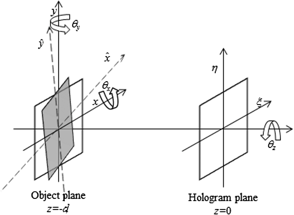
Fig. 2Conceptual flow chart describing how the extended focused image (EFI) is obtained by digital holography approach. Images are from Ref. 20.  Later, in addition to reflection configuration, Colomb et al.22 extended this scheme to transmission one. Furthermore, they generalized the application to other areas, such as metrology. For example, the method is employed on phase reconstructions of micro-optics (microlens and retroreflector, see Fig. 3), as well as on amplitude ones. They extracted the extended focus phase image from a stack of reconstructions using a generalized reconstruction distance map. where in reflection and in transmission, and is the longest reconstruction distance.Fig. 3Amplitude (1) and phase (2) reconstructions of a high aspect-ratio retroreflector immersed in distilled water measured in transmission for different reconstruction distances (a) 3.6 cm, (b) 6.6 cm, (c) 11.0 cm, and (d) EFI. Images are from Ref. 22.  Figure 3 presents the amplitude and phase reconstructions obtained for a high-aspect-ratio retroreflector, measured in transmission at and computed with different reconstruction distances. The reconstruction distance map is computed by adjusting the reconstruction distance to focus the retroreflector edges [Fig. 3(a)]. The EFI for the amplitude and phase are presented in Fig. 3(d). Ultimately, this method allows reconstruction of not only the extended focused amplitude images, but also, especially, the real topography for an object higher than the DOF of the microscope objective. A typical drawback of this digital holographic EFI technology is that it works only with a single object with an axial dimension larger than the DOF.23 Instead, in case of multiple objects sparsely distributed in the space, or when the 3-D object shape is not continuous or slowly varies, such as step-like height structures, it has difficulty in automatically identifying multiple, unknown shaped targets and transferring them into their respective best focal position. In this case, an algorithm able to recognize the presence of multiple targets should be used. It provides a chance to deal separately with these objects, and for each one, a map of heights is to be calculated. At this point, it refocuses each target, respectively, to their best focal planes and, finally, merges them back to form a high-precision 3-D shape result. Also, this type of technique belongs to the category of so-called sectioning and merging, and several attempts have been presented. For example, by the independent component analysis technique or discrete wavelet transform, Do et al.24–26 have synthetized an EFI from reconstructed holographic images of many 3-D objects at different in-focus distances. They achieved visual success. Nevertheless, their methods incurred the problem of blurring, since in the merge phase, more or less out-of-focus images are taken into account. For optical scanning holography, some authors27–29 have suggested modeling the task of sectioning as an inverse problem and Wiener filtering or iterative algorithms were implemented. Although these methods have reported remarkable results, they only worked for amplitude recovery. Holographic phase information was lost during processing so they cannot be used for purely phase objects. A most effective approach is to separate the whole image into small blocks, as described in Refs. 3031. to 32. A focal measurement algorithm is applied to each individual block and the best focal position is calculated. EFI is sewn by taking the best focal positions for all blocks. When a large number of objects are present, such as small particles, this idea can be brought to the limit, assessing the best distance pixel-wise to obtain the depth map for each pixel of the image.33 Anyway, a possible critical point is the choice of focus detection criteria. Typically, many reconstructed frames are collected along the axial direction, and the best focus plane is chosen by a certain kind of sharpness indicator. A number of various focus metrics have been proposed using an intensity gradient,34 self-entropy,35,36 gray-level variance,37 spectral norms,38 wavelet theory,39 and stereo disparity,40 among others; for a comparison between these methods, see Ref. 41. The majority of focus-finding applications consist of looking for the amplitude extrema, even though in many cases it is phase contrast that is actually of interest. However, another problem arises when, in the examined block, there are not enough features (either presenting no object or being occupied by a whole object yet with no significant change during digital refocusing), which makes it difficult to find the exact focus plane with the focus detection algorithms. 3.1.2.Multiplane imagingIn many fields of science, such as imaging particle fields, in vivo microscopy, optical propagation studies, wavefront sensing, or medical imaging, multiplane imaging is very common and useful, allowing simultaneous visualization of several layers within the imaged volume.42 This is another way to preserve a wide DOF without sacrificing the axial resolution of the objective lens. In practice, the imaging path is multiplexed with beam splitters into multiple paths, each with a different focal length and its own camera for imaging.43 In this way, full axial resolution of the microscope objective is maintained in each of the recorded images. Nevertheless, this approach is quite impractical and has different limitations. A different and smart approach has been proposed in the work of Blanchard and Greenaway44 in which a diffraction grating has been adopted in the optical setup to split the propagating optical field into three diffraction orders (i.e., 1, 0, ). The grating was distorted with an opportune quadratic deformation and, consequently, the wave field resulting from each diffraction order could form an image of a different object plane. A further investigation was published some years later, in which the focusing properties of a diffraction grating having parabolic grooves has been exploited for extending the depth of focus.45,46 More recently, remarkable progress has been made in the use of a quadratic deformed grating for multiplane imaging of biological samples to demonstrate nanoparticle tracking with nanometer resolution along the optical axis.47 To confirm the high interest in multiplexing imaging, in Ref. 48, an approach named depth of field multiplexing is reported. A high-resolution spatial light modulator was adopted in a standard microscope to generate a set of superposed multifocal off-axis Fresnel lenses, which sharply image different focal planes. This approach provides simultaneous imaging of different focal planes in a sample using only a single camera exposure. The maximum number of imaged axial planes is further increased in Ref. 49 using colored RGB illumination and detection. In their paper, the authors have demonstrated the synchronous imaging of as many as 21 different planes in a single snapshot under certain conditions. In DH, Paturzo and Finizio50 demonstrated that the synthetic diffraction grating can be included in the numerical reconstruction to simultaneously image three planes at different depths. In practice, in the numerical reconstruction algorithm, the hologram is multiplied by the transmission function of a quadratically distorted grating. where and control the relative contrast between the images corresponding to the orders and the central one, is the quadratic deformation, and is the grating period.The insertion of such a digital grating allows the simultaneous imaging of three object planes at different depths in the same field of view. In fact, the digital deformed grating has a focusing power in the nonzero orders and, therefore, acts as a set of three lens of positive, neutral, and negative powers. In the reconstruction plane, three replicas of the image appear; each one is associated with a diffraction order and has a different level of defocus. The distance from the object plane, corresponding to the ’th order, to that in the zeroth order is given by where is the reconstruction distance, is the number of pixels of size , while is the defocus coefficient.To demonstrate their technique, they performed different experiments. In the first case, three different wires were positioned at different distances from the CCD array of 100, 125, and 150 mm, respectively. A digital hologram was recorded in a lens-less configuration. They performed two numerical reconstructions of the corresponding hologram at 125 mm, the in-focus distance of the twisted wire, but with two different quadratic deformations of the numerical grating, that is two different values of the parameter . Figure 4 shows the amplitudes of the obtained reconstructions. Fig. 4Numerical reconstructions of the “three wires” hologram at , the in-focus distance of the twisted wire, with two different values of the numerical grating quadratic deformation in order to obtain: (a) the vertical wire in focus in the order image and (b) the horizontal wire in focus in the order image. Images are from Ref. 50. 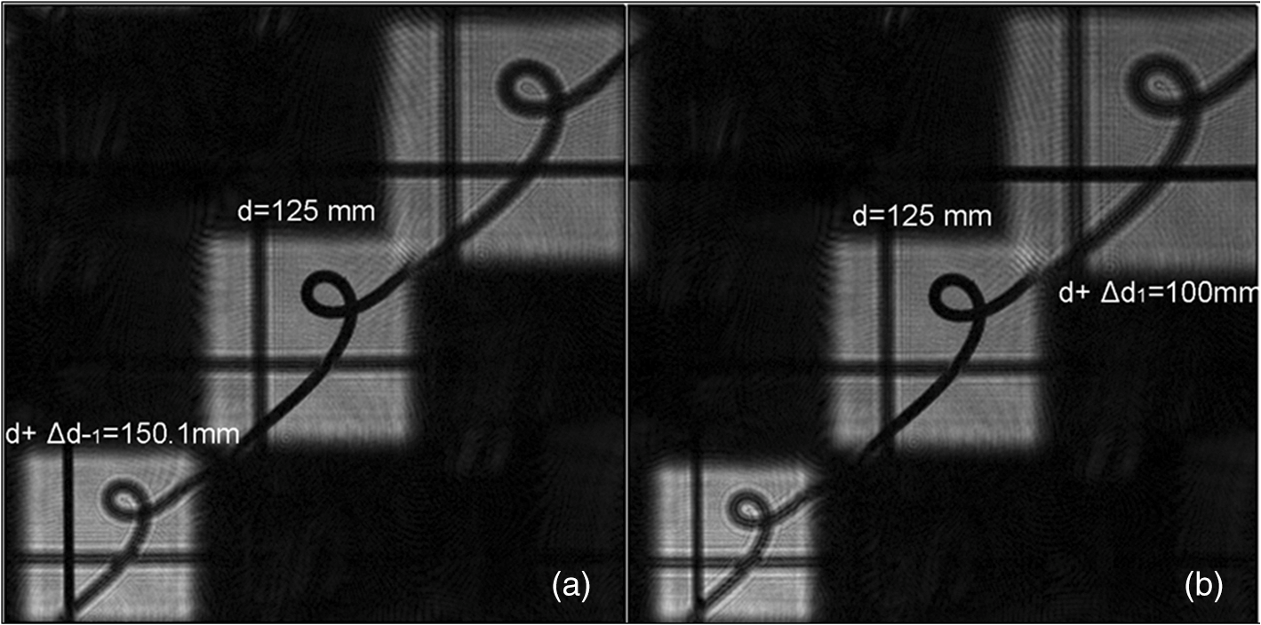 As a further experiment they also applied the method to holograms of a biological sample. The specimen is formed by three in vitro mouse preadipocyte 3T3-F442A cells that are at different depths. Figure 5 shows the amplitude reconstruction at a distance at which the cell indicated by the blue arrow is in focus (see the zeroth-order image). The order corresponds to a distance at which the cell indicated by the yellow arrow is in good focus, while the order corresponds to a depth of , where the filaments are visible (highlighted by the red ellipse in Fig. 5). Fig. 5Amplitude reconstruction of a “cells” hologram at a distance at which the cell indicated by the blue arrow is in focus. The order corresponds to a distance at which the cell indicated by the yellow arrow is in good focus, while the order corresponds to a depth of where the filaments are well visible, highlighted by the red ellipse. Images are from Ref. 50. 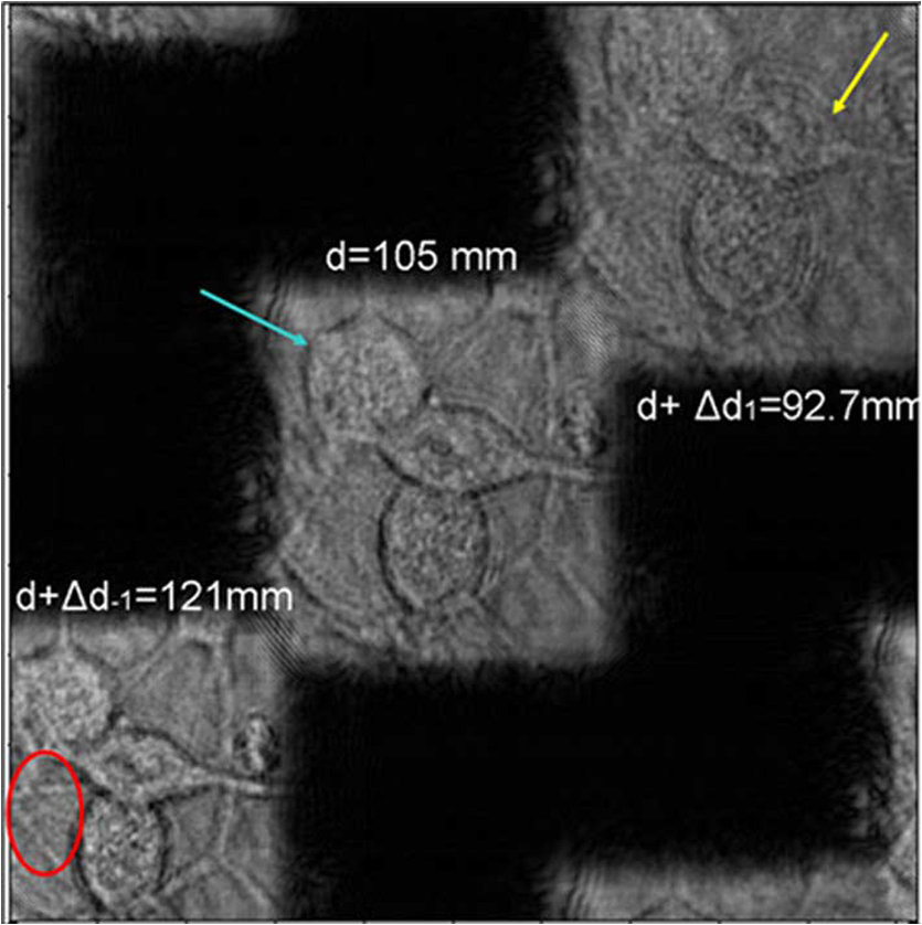 The use of a numerical grating instead of a physical one, has the great advantage of increasing the flexibility of the system. For example, depending on the grating period and the amount of deformation, the distance of the multiple planes can be easily changed and adapted to the needs of the observer. Moreover, they verified that the adoption of a deformed diffraction grating can be exploited in multiwavelength DH. Afterward, Pan51 presents an angular spectrum method (ASM)-based reconstruction algorithm to simultaneously image multiple planes at different depths. A shift parameter is introduced in the diffraction integral kernel. It takes account of the coordinate system’s transverse displacement of the image plane at different depths. A combination of the diffraction integral kernel with different shift values and reconstruction depths yields multiplane imaging resolution in a single reconstruction. Furthermore, a method to extend the depth of focus using a single-shot digital hologram is also proposed. 3.1.3.3-D imagingThe very important advantage of DH is that all the 3-D information intrinsically contained in the digital hologram, can be usefully employed to construct a single image with all portions of a 3-D object in good focus. However, the question of the relationship between the 3-D distribution of the wave field and the configuration of the object is still not solved. Consider the first case with a single wavelength and a single propagation direction of the illuminating wave (single -vector): the reconstructed wavefront contains all contributions originating from all parts of the specimen and cannot be considered as the true 3-D image of the object. Indeed, the coherent source produces interferences with each of the reflected or transmitted waves or, more generally, diffracted waves coming from each part of the object. The final image is then the superposition of the contributions from all the sections, in addition to the one where the wavefront is reconstructed (in-focus plan). The contributions of the upper and lower sections of the object (out-of-focus plans), therefore, appear as undesired contributions that blur the image. A major objective of the research is to adequately solve the problem of true 3-D object imaging by the elimination of all unwanted contributions. In holographic microscopy, different strategies exist to solve this problem. Initially, Onural52 extended the impulse function concept over a curve or a surface and he used it to improve the structure of the diffraction problem formulation, thus paving the way for elegant solutions of many associated problems. However, these require 3-D Fourier transforms, integrals over surface, and rotation matrices, making the problem numerically difficult to treat. In Refs. 53 and 54, 3-D deconvolution methods with a point spread function (PSF) are extended to holographic reconstructions with the aim to rebuild the true 3-D distribution of small particles. Unfortunately, 3-D deconvolution products require a high amount of memory and data resampling is often necessary, implying a loss of spatial resolution. 3-D data were retrieved by Pégard and Fleischer55 using 3-D deconvolution in microfluidic microscopy. In particular, the focal stack generated by tracking samples flowing into a tilted microfluidic channel [see Fig. 6(a)] and the system PSF [Fig. 6(b)] are processed in a Wiener deconvolution filter to extract size, position, orientation, and subcellular surface features of aggregated yeast cells, Fig. 6(c). Fig. 6(a) Focal stack and (b) point spread function (PSF) focal stacks are recorded in a deconvolution microfluidic microscopy. The three-dimensional (3-D) structure of the object is deconvolved and an iso-level surface showing the 3-D envelope of yeast particles is displayed (c). Images are from Ref. 55. 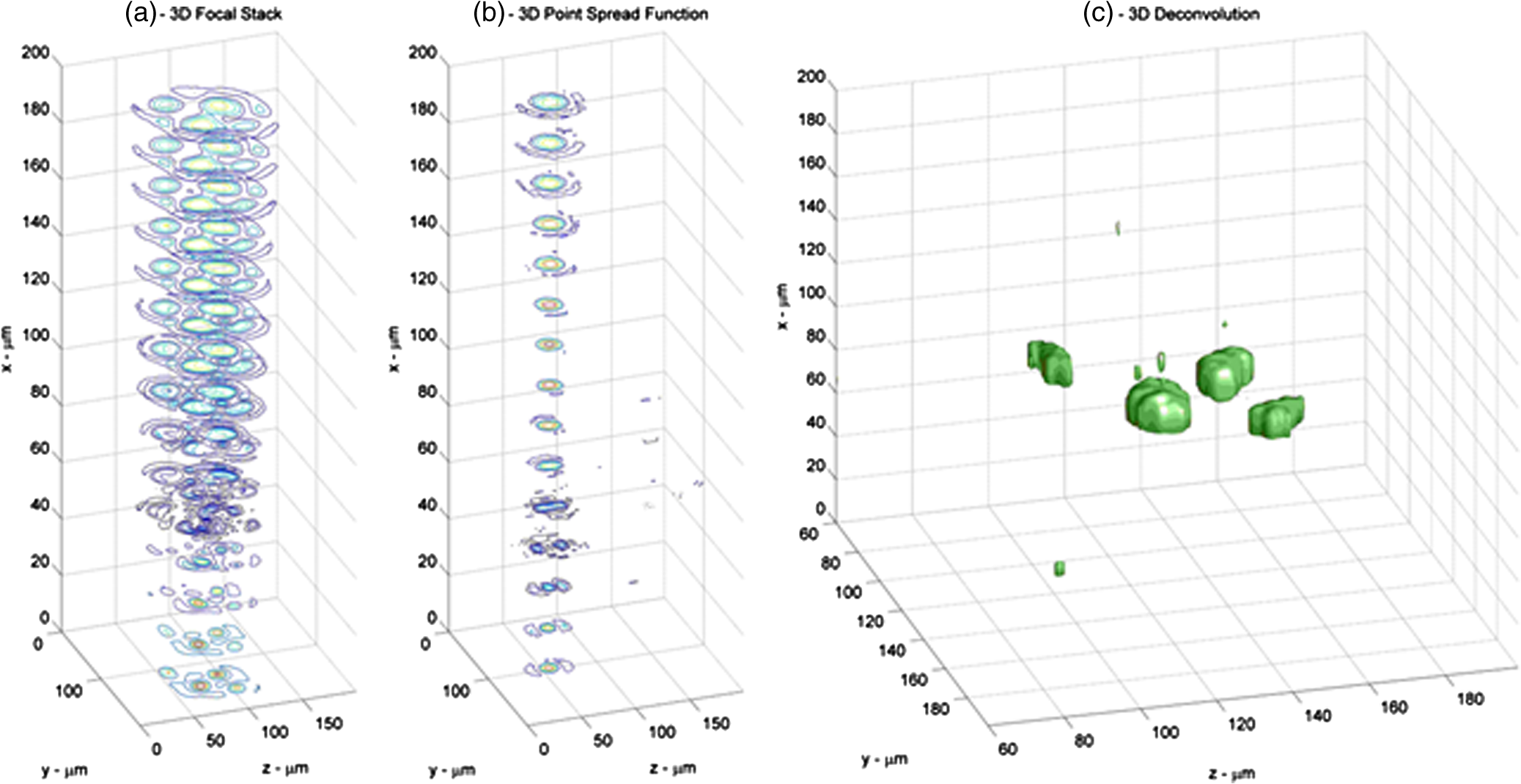 In diffractive tomography, Cotte at al.56 combined the theory of coherent image formation and diffraction. Through an inverse filtering obtained by a realistic coherent transfer function, namely 3-D complex deconvolution, they enabled the reconstruction of an object scattered field. The authors expected this technique to lead to aberration correction and improved resolution. By combining the advantages of full-field frequency-domain optical coherence tomography with those of photorefractive holography, Koukourakis et al.57 proposed a system for a complete 3-D image. In their system, a 3-D stack of spectral interferograms is constructed to obtain depth information. This setup employs a wavelength scanning tunable laser as the light source, and the use of a photorefractive medium to holographically store the spectral interferograms obtained by scanning the wavelength. 3.2.Reconstruction in a Tilted PlaneWe dedicate a separate section to techniques proposed over the years to solve the case of an image plane tilted with respect to the object one. The need to propagate fields between tilted planes has probably increased with the advance of integrated optical circuits. They are often constructed with crystal structures that work efficiently only for certain directions, though usually not orthogonal to the optical axis. Furthermore, in modern biology and medicine, some techniques, like total internal reflection (TIR) holographic microscopy, are of great interest to perform quantitative phase microscopy of cell-substrate interfaces. Unfortunately, they use a prism that alters the geometry of the typical acquisition systems, thus requiring special solutions. Therefore, in all these cases and others, such as in tomographic applications, if one is interested in inspecting the object characteristics on a plane tilted with respect to the recording hologram one, such as illustrated in Fig. 7, it is more efficient to develop a method capable of reconstructing the hologram at arbitrarily tilted planes. Basically, this means simulating light propagation through diffraction calculation between arbitrarily oriented planes. 3.2.1.Diffraction between arbitrarily oriented planesLeseberg and Frère58 were the first who addressed the problem of describing the diffraction pattern of a tilted plane using Fresnel approximation. It is calculated by a Fourier transformation, a coordinate transformation, and a multiplication by a quadratic phase. Later on, a general-purpose numerical method for analyzing optical systems by the use of full scalar diffraction theory was proposed by Delen.59 His approach is based on Rayleigh-Sommerfeld diffraction and it can be applied to wide angle diffraction. In particular, the author proposed two methods, one for shifted plane and the other one for tilted plane, and these can be sequentially combined for shifted and tilted planes. This is a very advantageous feature, because other methods are limited to rotation around one axis. For example, Yu et al.60 used Fourier transform method (FTM) for numerical reconstruction of digital holograms with changing viewing angles. Certainly, the use of the a plane waves angular spectrum and coordinates rotations represents a more flexible solution. Initially, Tommasi and Bianco61 proposed a technique for finding the relation between the plane-wave spectra of the same field, with respect to two coordinate systems rotated only with respect to each other, to calculate the computer-generated holograms of off-axis objects. Subsequently, De Nicola et al.62 and Matsushima63 proposed methods to obtain the EFI of objects or the target recorded on inclined planes, by taking the angular spectrum into consideration. The angular spectrum-based algorithm for reconstructing the wave field on arbitrary inclined plane basically consists of two steps. In the first one, the angular spectrum is calculated on an intermediate plane () at distance . Standard transformation matrix is then used to rotate the wave vector coordinates. This matrix is, in general, given as a rotation matrix or the product of several rotation matrices. In the second step, the rotate spectrum is inverse Fourier transformed to calculate the reconstructed wave field on the tilted plane, namely It should be remarked that reconstructing the field according to Eq. (24) is valid within the paraxial approximation. However, it can be generalized to include frequency-dependent terms of the Jacobian associated to rotation. Furthermore, the spectrum should be shifted in the reference Fourier space. Since the complex value of the spectrum has to be obtained for each sampling point on the equidistant sampling grid, interpolation is needed because of the nonlinearity attributed to Eq. (24). In summary, in these cases, fast Fourier transformation is used twice, and coordinate rotation of the spectrum enables one to reconstruct the hologram on the tilted plane. Interpolation of the spectral data is shown to be effective for correcting the anamorphism of the reconstructed image. In Fig. 8, a case of two-axis rotation is shown.63 The planar object is slanted at 30 deg around the y axis after rotation at around the axis. Therefore, the transformation matrix is used to retrieve the original pattern. Fig. 8Amplitude images (a) reconstructed in the parallel plane and (b) in the tilted plane reconstructed by using rotational transformation for two-axis rotation. The planar object is rotated at around the axis prior to rotation at 30 deg around the axis. Images are from Ref. 63.  Since these methods suffer from the loss of resolution problem, Jeong and Hong64 have presented an effective method for the pixel-size-maintained reconstruction of images on arbitrarily tilted planes. The method is based on the plane wave expansion of the diffraction wave fields and on the three-axis rotation of the wave vectors. The images on the tilted planes are reconstructed without loss of the frequency contents of the hologram and have the same pixel sizes. For example, Fig. 9(a) presents the hologram reconstruction of a 1951 USAF target rotated by and on the plane parallel to the CCD plane at using the ASM. The resolution target’s center is located on the optic axis at 2.42 cm in front of the CCD plane. It can be seen that the left-hand upper corner of the image is focused, while the other parts are out of focus because of object tilting. Figure 9(b) is the image at reconstructed with a correction method; it is focused across the whole area of the resolution target, but its pixel size is smaller than that of the hologram due to the scaling caused by the FFT. The image in Fig. 9(d), which was reconstructed by their method, is focused across the whole plane, and the ratio between the and the dimensions of the reconstructed resolution target is the same as that of the real object, which proves that their method can faithfully reconstruct images on the tilted planes. Fig. 9Reconstructed images of the tilted resolution target (). (a) Image on the plane parallel to the CCD at reconstructed with the ASM. (b) Images on the tilted plane at reconstructed from the whole area. (c) Image reconstructed by the method in Ref. 64.  The popularity of these techniques is now so extended that they are also successfully applied in many others fields such as biology.65–67 In particular, in the paradigm of TIR holographic microscopy, Ash et al. used angular spectrum rotation for imaging organisms, cell-substrate interfaces, adhesions, and tissue structures. Figure 10 shows a basic configuration of the interferometer for digital holographic microscopy of TIR. The object beam enters the prism and undergoes TIR at the hypotenuse A of the right-angle prism. The presence of a specimen on the prism surface modulates the phase front of the reflected light. Thanks to the prism presence, the object plane A optically appears to the camera, or to the plane H, at a certain angle of inclination, so an en face reconstruction result requires an algorithm that accounts for such an anamorphism. Fig. 10Apparatus for DH of total internal reflection. BS, beam-splitters; M, mirrors; L, lenses; A, object plane; H, hologram plane. Image is from Ref. 65.  In Fig. 11, the numerical correction procedure is depicted. The sample, Allium cepa (onion) cells, resides on the prism face and provides a direct image as shown in Fig. 11(a). With the addition of the reference beam, the CCD camera captures the hologram created by the superposition [Fig. 11(b)]. At that point, the hologram is processed into Fourier space, including filtering [Fig. 11(c)]. The complex array comprising the angular spectrum is then transformed back into real image space, yielding both the amplitude and the phase information [Figs. 11(d) and 11(e)]. If the untilting process is included in the reconstruction, the results are depicted in Figs. 11(g) and 11(h). In Fig. 11(f), a typical en face direct image of onion tissue is presented for comparison. Fig. 11Process of digital holographic microscopy with untilt via the angular spectrum method: engineering run with onion tissue (A. cepa). (a) Direct image with tilt. (b) Hologram. (c) Angular spectrum filtering first-order peak. (d) Amplitude image reconstruction with inherent tilt. (e) Phase image with inherent tilt. (f) Typical en face direct image of A. cepa. (g) Untilted (and transposed) amplitude. (h) Phase image. Image is from Ref. 66. 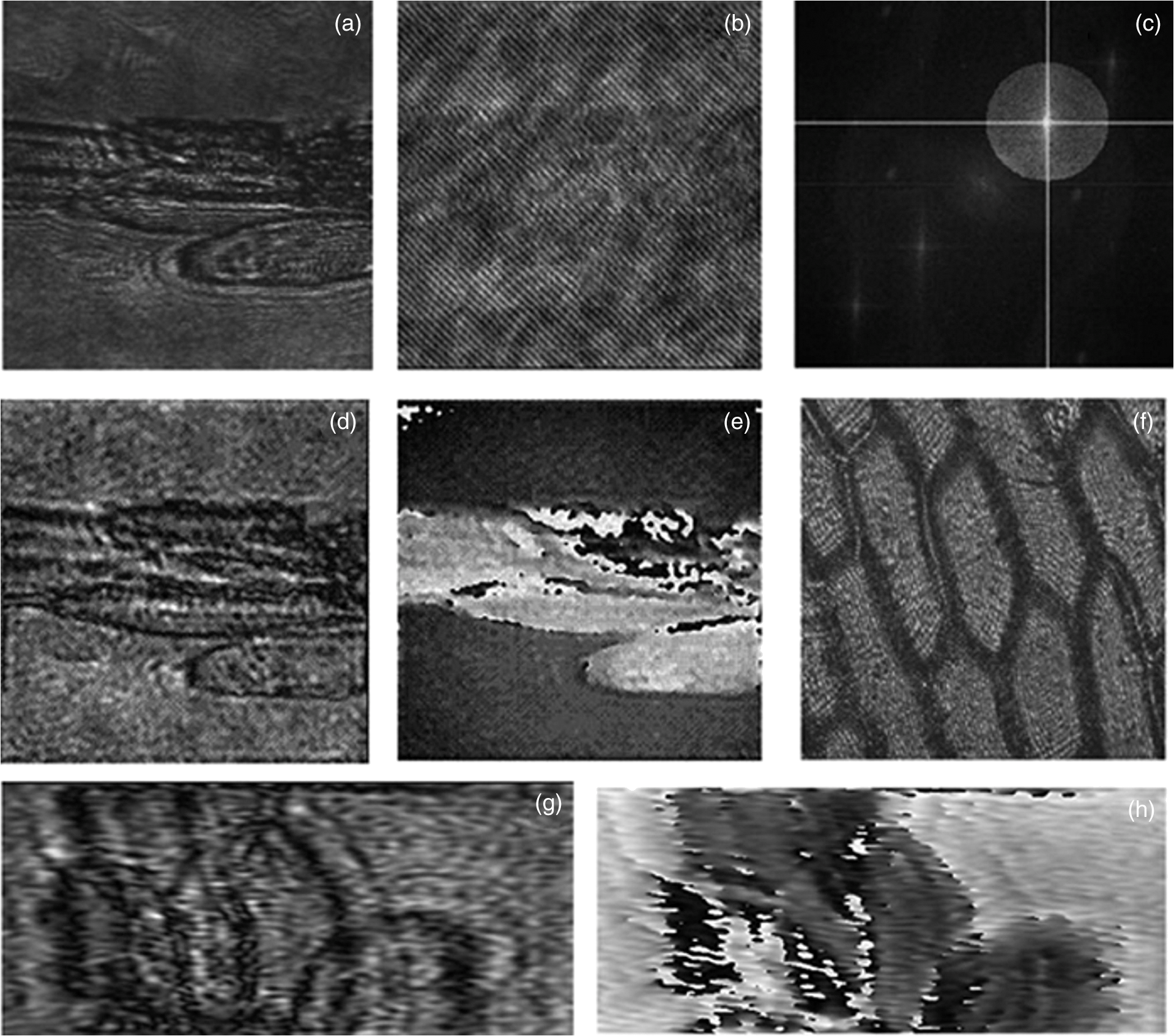 A 3-D version of this approach was introduced by Onural.68 He used the impulse function over a surface as a tool, converting the original 2-D problem to a 3-D problem. Even though its formulation is analytically correct, it is proposed only for the continuous case. Another method has been suggested by Lebrun et al.69 to extract information about a 3-D particle field in arbitrary tilted planes by DH. In particular, he used wavelet transform to reconstruct small particles in a plane whose orientation is arbitrary as specified by the user. The pixels, whose 3-D coordinates belong to this plane, are selected and juxtaposed to rebuild the particle images. More recently, a partial numerical Fresnel propagation technique of the complex wave has been proposed70 for tilted image planes refocusing, and some solutions are used to reduce the influence of aliasing and Fresnel diffraction in the process of numerical reconstruction. A scaled Fourier transform is used instead in Ref. 71 to calculate light diffraction from a shifted and tilted plane. It seems to be faster than calculating the diffraction by a Fresnel transform at each point, see, for instance, Ref. 72, and this technique can be used to generate planar holograms from computer graphics data. To simplify FTM and, at same time, solve the pixel size consistency problem, Wang et al.73 presented a GPU-based parallel reconstruction method for EFIs of tilted objects. In summary, they used fast Fourier transform pruning with frequency shift combined with coordinate transformation. Their method has high imaging precision and speed, but it requires GPU assistance and some specific knowledge. Generally, existing numerical methods for refocusing between inclined planes need a priori knowledge of the input scenes, such as the object size, and the average reconstruction tilting angle or distance, to properly adjust the EFI algorithm. Such a priori knowledge is easy to achieve in an academic experiment, but it is usually unknown for real experiments. In Ref. 74, Kostencka et al. proposed an appropriate tool for automatic localization of a tilted optimum focus plane. The method is based on the estimation of the focusing condition of the optical field by evaluating the sharpness in its amplitude distribution. The developed algorithm is fully automated. It consists of two major steps: first the rotation axis is localized from the map of local sharpness and then the angular orientation of the image plane is derived by maximizing the focus of optical fields reconstructed in many subsequent tilted planes. In the case of a highly tilted plane or 3-D shapes with high gradients, the strategies described so far have encountered several problems. For DH in microscopic configuration, two reconstruction algorithms are presented by Kozacki et al.75 The first is an extension of the well-known thin element approximation for tilted geometry, which can be applied to the case of large sample tilts, but it requires the sample numerical aperture to be low. The second one is called the tilted local ray approximation algorithm, and it is based on the analysis of local ray transition through a measured object. The authors proposed a modified algorithm for the numerical propagation between tilted planes, which can be applied for the shape characterization of tilted samples with a high shape gradient. 3.2.2.Phase plateIn conventional microscopy, another possible solution for extended DOF is wavefront coding. This method was introduced by Dowski et al.8–10 more than a decade ago. Wavefront coding introduces a known, strong optical aberration that dominates all other terms, like defocus. This circumstance causes the optical system to be essentially focus-invariant over a large range, so straightforward computational tools can be used to recover image information. Under this imaging paradigm, several variants have been proposed.12,76,77 Quirin et al.77 have used a wavefront coded imaging system coupled to a spatial light modulation (SLM)-based illumination system, see Fig. 12, to image fluorescence from multiple sites in three dimensions, both in scattering and transparent media. Fig. 12Design of extended depth of field (EDOF) microscope. (a) Experimental configuration of the joint spatial light modulation and EDOF imaging microscope for 3-D targeting and monitoring. The detailed description of each component is described in Sec. 4.1 of Ref. 77. The phase aberration shown in (b) is the ideal diffractive optical element for the cubic-phase modulation and placed in an accessible region between L9 and L10 without affecting the illumination pupil. The experimental PSF of the imaging system is presented for the conventional microscope in (c) and the EDOF microscope in (d). The 3-D volumes in (c) and (d) represent the 50% intensity cutoff of each axial plane and the axis units are in micrometer.  For example, experimental results for the 3-D SLM illumination in transparent media, with both the conventional and extended DOF microscope, are shown in Fig. 13. In this case, a sample is translated axially from the classical focal plane (defined as ) in 4-μm intervals while another is held fixed in the focal plane (600 μm below the surface of the media), as shown in Fig. 13(a). The results from a conventional imaging microscope are presented in Fig. 13(b). For SLM microscopy, a rapid loss of imaging performance occurs as the illumination translates beyond the narrow focal plane. In contrast, the restored image from the extended DOF microscope is presented in Fig. 13(c), which shows a relative increase in the out-of-focus signal and tightly localized points, regardless of axial location. Although the results are clearly visible and noticeable, their extended DOF microscope requires a priori information on the target locations imprinted on the system by user. Fig. 13The 3-D illumination pattern is shown in (a). The results from imaging the 3-D pattern in bulk fluorescent material are given for the conventional microscope (b) and the EDOF microscope (c). Images are from Ref. 77. 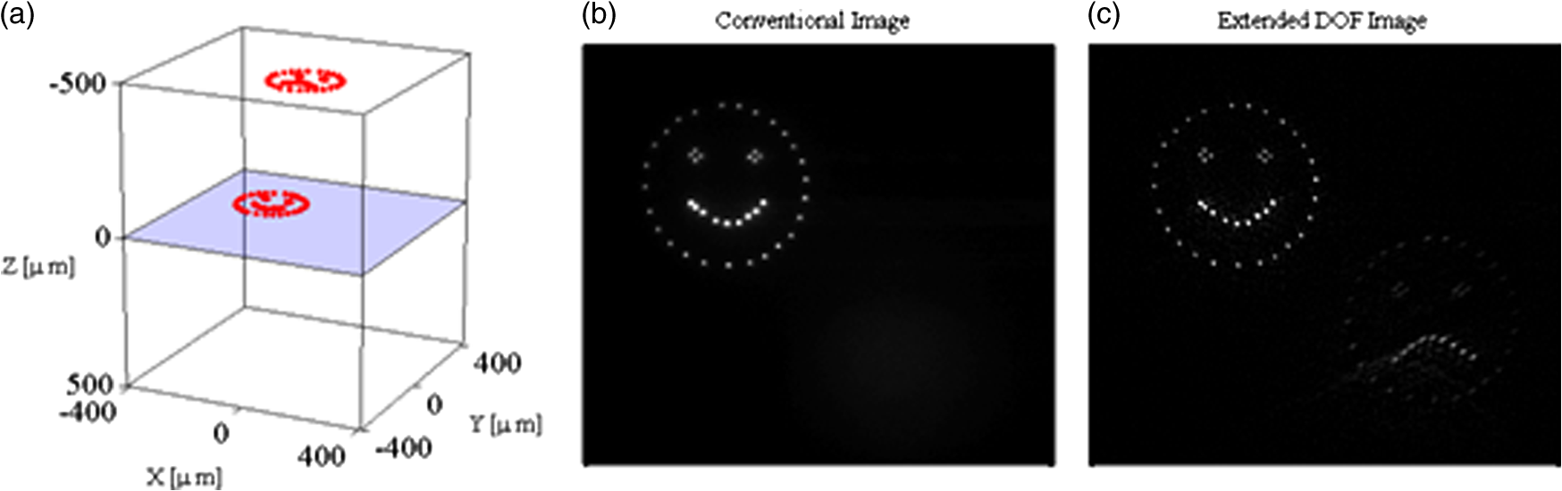 In analogy to what is proposed by Dowski, Matrecano et al.78 showed that a cubic phase plate (CPP) can be easily and conveniently included into the numerical reconstruction of digital holograms for enhancing the DOF of an optical imaging system and for recovering the EFI of a tilted object in a single reconstruction step. Moreover, they offered clear empirical proof through different appropriate experiments: the first one on an amplitude target and the others on biological samples. The advantage is in the possibility of avoiding the use of real optical components together with the related complex fabrication process required by a continuous cubic phase plate with a high phase deviation. They propose to modify the numerical reconstruction algorithm. In particular, the hologram is multiplied by a numerical CPP, with a pupil function given by where is the half width of a square CPP and is a phase modulation factor determining the maximum phase deviation along the axes, given by . The simulated phase distribution of a numerical CPP with and is shown in Fig. 14(a). A phase distribution of this kind is really difficult to fabricate because of its high phase deviation; in fact, it is typically decreased into a relief structure with a phase modulation; see Fig. 14(b). Since in a numerical problem formulation this process is unnecessary, very high phase deviations can be easily realized.Fig. 14Phase distribution of a two-dimensional (a) and one-dimensional cubic phase plate (CPP), along the x-coordinate (c). In (b) and (d) are shown their mod- representation. 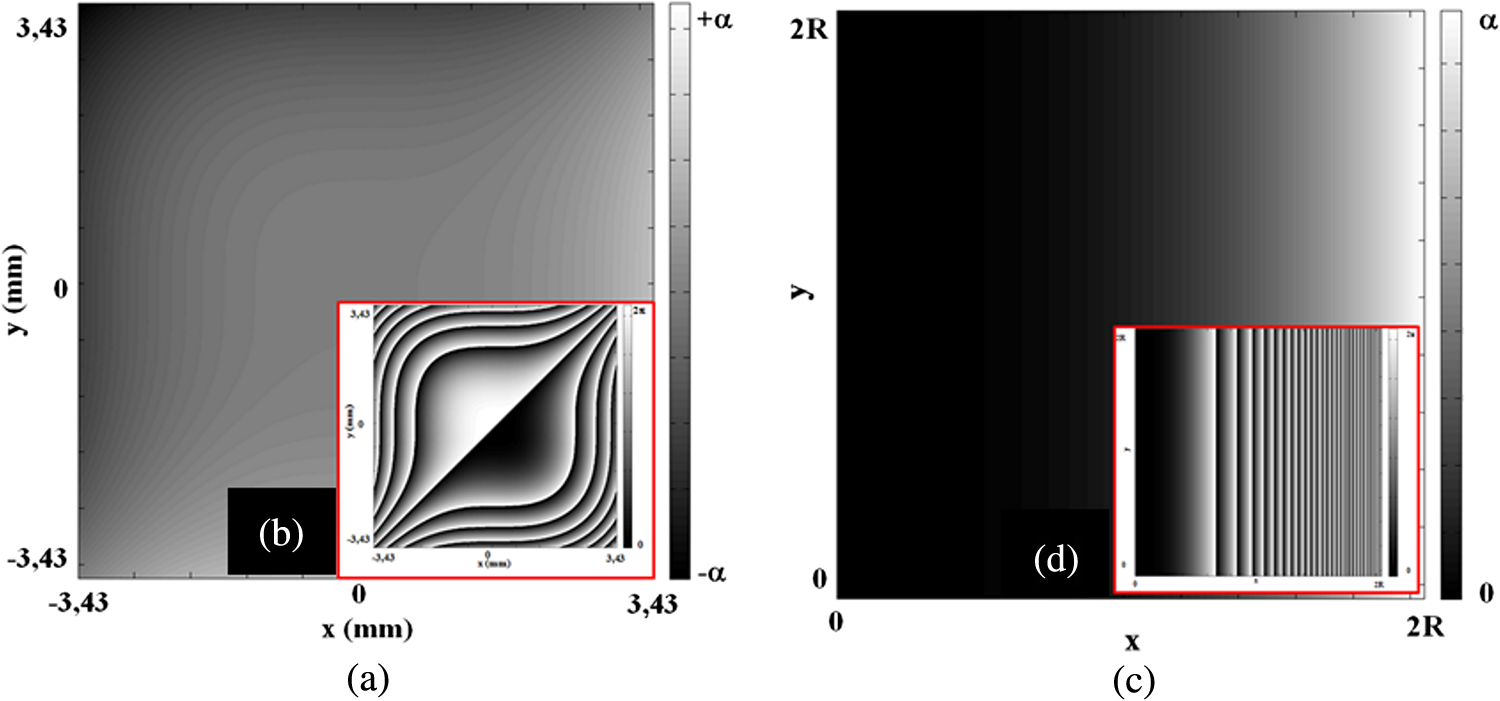 In Eq. (25), a general 2-D phase delay is expressed as a function of both spatial coordinates. But, if an object is tilted by angle around the vertical axis during the reconstruction, the defocus varies along only the horizontal axis. Taking this into account, they modified the phase delay allowing it to become function only of the coordinate. Moreover, this consideration allows one to somehow interpret the cubic term influence within the reconstruction process. In general, quadratic terms44,50 are used to compensate the defocus. In this case, it is not uniform but varies along the spatial coordinate. The effect is to change very little the areas near the focus distance very little, and, proportionally, to change the distant ones much more. The use of a numerical CPP, instead of a physical one, has the great advantage of increasing the system flexibility. In fact, by varying the amount of phase delay ( value) and the plate width ( value), they can obtain an EFI notwithstanding the tilt angle or the image size. In particular, considering a reconstruction algorithm and the introduced phase delay, through simple algebraic calculations, they obtain The simulated phase distribution along , with and , is shown in Fig. 14(c); its corresponding modulus representation is shown in Fig. 14(d). To show how the CPP introduction impacts the imaging in microcopy, they performed different experiments. Initially, they made an experiment with a Mach-Zehnder interferometer in Fourier configuration. The setup is a Mach-Zehnder interferometer in transmission configuration, and the laser wavelength is 0.532 μm while the CCD pixel size is 6.7 μm. A USAF resolution test chart was positioned in a tilted way with respect to the laser light illumination direction. The Fourier holographic configuration is such that the reference beam curvature matches that of the light scattered by the left side of the object (where the biggest number “1” is located). Consequently, this region is in-focus in the numerical reconstruction. On contrary, the target right side (where the number is “0”) is completely out of focus in the numerical reconstruction. In Figs. 15(a) to 15(c), the numerical reconstructions for the target tilted with an angle , 55, and 75 deg are shown, respectively. The portion on the left side of the object is in focus, while the right part is out of focus and the focus gradually worsens going from the left to right. Instead, if a CPP is added before performing the numerical reconstruction (with an opportune choice of the parameter ), a DOF enhancement occurs, putting all tilted target details in good focus[see reconstructed images in Figs. 15(d) to 15(f)]. Fig. 15Numerical reconstruction of the holograms for an object tilted with an angle of 50 (a), 55 (b), and 75 deg (c) as acquired by the CCD and after the CPP introduction, to obtain the EFI [(d), (e), and (f)]. Square insets are magnified view of circled areas for each color, respectively. 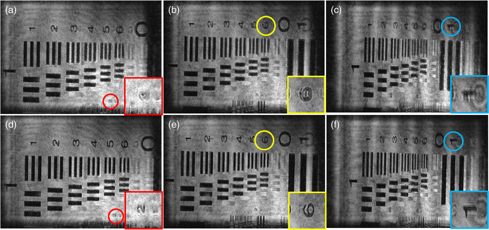 Moreover, they analyzed holograms relative to bovine spermatozoa, prepared by the Institute “Lazzaro Spallanzani” after fixation in seminal material suspension (see also Ref. 79). Figure 16 presents the quantitative phase maps, also in pseudo 3-D, between hologram reconstructions with, Figs. 16(c) and 16(d), and without the CPP, Figs. 16(a) and 16(b), for . Even in this case, since the focus is on the left, the contours of the spermatozoon on the right appear blurred and the tail is not well defined, see Figs. 16(a) and 16(b). Instead, in Figs. 16(c) and 16(d) (i.e., in the EFIs), both the head and the tail are distinguishable. Moreover, in pseudo 3-D phase reconstruction, a typical maximum into the head region, indicated by an arrow, is now clearly visible. Fig. 16Reconstructed quantitative-phase-map of bovine spermatozoa at , obtained without (first row) and with a CPP (second row). In pseudo 3-D reconstructions (d), the arrow indicates a phase maximum, which is visible only in reconstruction with a CPP. 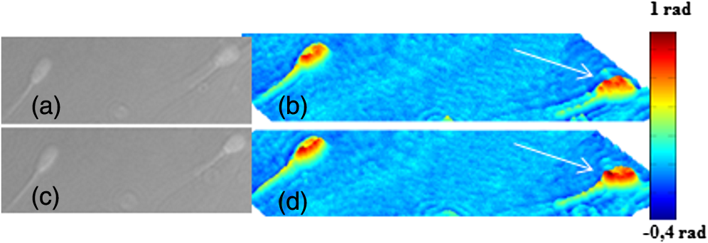 As an application example in the case of arbitrarily tilted planes, the authors applied a numerical CCP to a 2-D grid, composed of poly-co-glycolic acid (PLGA) ink written onto a polydimethylsiloxane coated glass slide using a pyroelectrodynamic approach.80 Figure 17(a) shows the grid amplitude reconstruction at a distance . At this distance, only the area along the diagonal, from left to right, is reconstructed in focus, while the PLGA fibers deposited along the lateral zones appear blurred and poorly defined, as highlighted by colored circles in Fig. 17(a). Through the correction of numerical CPP, the 2-D grid is reconstructed entirely in focus, see Fig. 17(b). The colored circles indicate that a depth of focus improvement occurred both along the horizontal and vertical directions. This shows the method can be applied to fix the anamorphism problem for arbitrarily tilted planes. Fig. 17(a) Grid amplitude reconstruction at . (b) Grid amplitude reconstruction at after CPP correction. Colored circles show a depth of focus improvement along both directions. 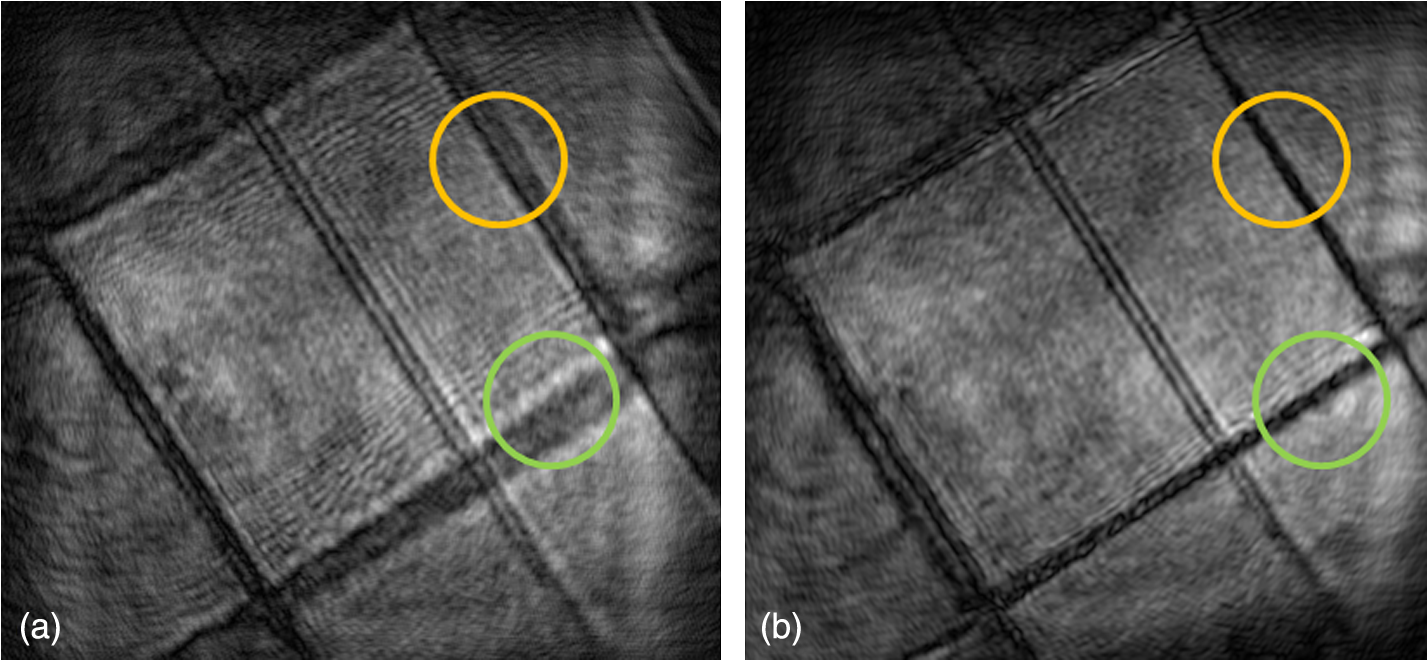 The results definitely point out that this method allows one to obtain, in a simple and straightforward way, the EFI construction of a hologram recorded on a tilted plane. 3.2.3.Geometrical hologram deformationFor tilted plane anamorphism correction, Paturzo et al.81,82 proposed a significantly different approach. In particular, through a suitable quadratic deformation of digital holograms, they were able to construct the EFI of some targets, in general, to manage the depth of focus in 3-D imaging reconstruction. They considered a spatial polynomial deformation. where the operator is given byIf the sample is tilted only along one direction and the deformation is applied along the other one with suitable values of and for the parameters, they recovered the EFI for tilted targets in a DH microscope. One example is displayed in Fig. 18. In this case, the tilted object is a silicon wafer with the letters “MEMS” written on it. The target is tilted with an angle of 45 deg with respect to the optical axis of the DH system. The deformation was applied only along the axis with and . Figure 18(a) shows the reconstruction of the undistorted hologram at a distance of . It is important to note that the portion of the object with the letter “S” is in good focus, while the remainder is gradually out of focus. Figure 18(b) shows the reconstruction obtained on the quadratically deformed hologram, and it shows that now all the letters “MEMS” are in good focus, demonstrating that the EFI has been obtained. Figure 18(c) also shows the phase map difference calculated by subtracting the two holograms, indicating that the defocus tilt has been mainly removed. Fig. 18Quadratic deformation applied along the axis to a hologram of a tilted object. (a) First frame from the video showing how EFI is got by adaptive deformation. (b) EFI image. (c) Phase difference. Images are from Ref. 81. 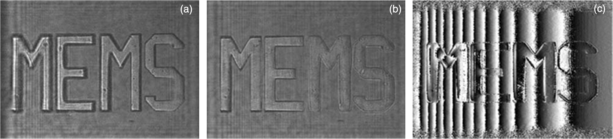 The great advantage of this approach is in its extreme simplicity; it is direct and quite effective, but unfortunately the hologram transformation causes some deformations in the reconstruction. Anyway, digital holograms’ spatial and adaptive transformations are the key tools for creating a dynamic action of real-world objects, as proposed in Ref. 83. Though the EFI issue is not of major concern, this technique is interesting for handling the in-focus distance. In their work, a 3-D scene is synthesized by combining multiple optically recorded digital holograms of different objects. The synthetic holograms can be given as input to any SLM array for optical reconstruction. The result is a 3-D scene truly observable of 3-D real-world objects projected in a volume in front of the SLM. This technique allows full control in manipulating an object’s position and size in a 3-D volume with a very high depth of focus. 3-D dynamic scenes can be projected as an alternative to the complicated and heavy computations needed to generate realistic-looking computer-generated holograms. 3.2.4.Selected applicationsIn this section, we want to compare some of the techniques described in the previous ones. The aim is to show how these methods work under the same conditions, proposing different applications. Figure 19(a) presents the hologram of a target tilted with an angle . In Fig. 19(b), the amplitude reconstruction at is shown. At this reconstruction distance, the image on the right side is in good focus, while the left one is out of focus. The results shown in Figs. 19(d), 19(e), and 19(f) are obtained by applying the method of angular spectrum rotation, numerical CPP, and quadratic hologram deformation, respectively. As one may notice, an extended focused image of the tilted target, in which the details are reconstructed in focus, is obtained. The differences between the first two techniques are almost nonexistent, while for the method using a spatial hologram transformation, the image on the left side still appears blurred and some deformation artifacts are visible. The reason for this poor performance is due to the high rotation angle and the numerical interpolations. For comparison, Fig. 19(c) shows the EFI obtained by a traditional sectioning and merging approach, as proposed by Ref. 23 for tilted objects. This result represents the ground truth for this type of application, because it is constructed by collecting only the in-focus parts in a single image. The results’ evaluation shows that the techniques using angular spectrum rotation and numerical CPP return results entirely comparable with the traditional ones, but with the unquestionable advantage that they are simple, direct, faster, and less error-prone. Fig. 19Comparison between exposed techniques. (a) The recorded digital hologram. (b) Digital reconstruction at . (c) EFI obtained by traditional sectioning and merging approach. (d) Reconstruction by angular spectrum rotation method. (e) Reconstruction after the numerical CPP introduction. (f) Reconstruction after a hologram quadratic deformation. 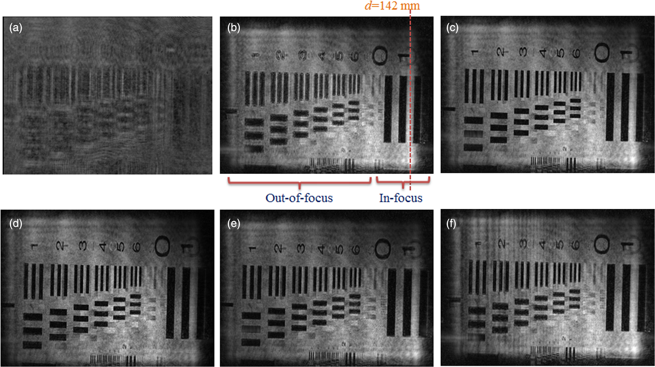 One can observe analogous results on the amplitude reconstruction of these biological samples. Figure 20(a) presents the hologram of two fibroblast cell lines NIH-3T3 flowing in a microchannel tilted . In Fig. 20(b), the amplitude reconstruction at a distance is shown. Since the smaller cell moves away from the focus distance (again, on the left side of the image), it appears more blurred with respect to the bigger one. The amplitude reconstructions at same distance, but after the numerical corrections of angular spectrum rotation, numerical CPP, and quadratic deformation, are shown in Figs. 20(d), 20(e), and 20(f), respectively. After the use of the above methods, the edges of the second cell appear thinner and not more blurred along the entire microchannel length. The results obtained are almost completely superimposable with the EFI synthesized by a conventional approach in Fig. 20(c). Fig. 20Comparison between exposed techniques. (a) The recorded digital hologram. (b) Digital reconstruction at . (c) EFI obtained by traditional sectioning and merging approach. (d) Reconstruction by angular spectrum rotation method. (e) Reconstruction after the numerical CPP introduction. (f) Reconstruction after a hologram quadratic deformation. 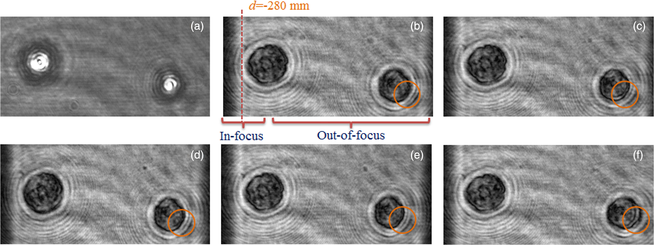 4.ConclusionIn this work, we have discussed the main attempts for extended focus image synthesis. This is really a crucial issue within the scientific community, considering the absolute, and always more pressing need to represent 3-D objects, or multiple objects, completely in focus in a single image. The efforts are oriented in different directions, both in hardware terms to break down the limited DOF barrier, typical of many optical imaging systems, both in numerical terms, pointing on pre-or-post image processing. In this paper, we have identified two main categories of application: the methods used to represent in-focus 3-D objects and other ones proposed to display in-focus objects recorded on a tilted plan. For each section, the most significant strategies were briefly discussed and possibly illustrated with examples. Finally, in the last section, we have directly compared some of the described techniques, testing them on the same hologram and comparatively evaluating the obtained results. The aim is to provide the reader with a valuable assessment tool to discern, in the vast scenery of the proposed methodologies, the advantages and disadvantages of each approach. ReferencesG. Häusler,
“A method to increase the depth of focus by two step image processing,”
Opt. Commun., 6
(1), 38
–42
(1972). http://dx.doi.org/10.1016/0030-4018(72)90243-X OPCOB8 0030-4018 Google Scholar
R. J. PieperA. Korpel,
“Image processing for extended depth of field,”
Appl. Opt., 22
(10), 1449
(1983). http://dx.doi.org/10.1364/AO.22.001449 APOPAI 0003-6935 Google Scholar
V. Tympel,
“New high-level image capture system for conventional light microscopy,”
Proc. SPIE, 2707 529
–536
(1996). http://dx.doi.org/10.1117/12.238483 PSISDG 0277-786X Google Scholar
V. Tympel,
“Three-dimensional animation with conventional light microscopy,”
Proc. SPIE, 2984 190
–198
(1997). http://dx.doi.org/10.1117/12.271267 PSISDG 0277-786X Google Scholar
S. SugimotoY. Ichioka,
“Digital composition of images with increased depth of focus considering depth information,”
Appl. Opt., 24
(14), 2076
–2080
(1985). http://dx.doi.org/10.1364/AO.24.002076 APOPAI 0003-6935 Google Scholar
B. Williset al.,
“Developments in three-dimensional stereo brightfield microscopy,”
Microsc. Res. Tech., 24
(5), 437
–451
(1993). http://dx.doi.org/10.1002/(ISSN)1097-0029 MRTEEO 1059-910X Google Scholar
A. G. Valdecasaset al.,
“On the extended depth of focus algorithms for bright field microscopy,”
Micron, 32
(6), 559
–569
(2001). http://dx.doi.org/10.1016/S0968-4328(00)00061-5 MICNB2 0047-7206 Google Scholar
E. DowskiW. Cathey,
“Extended depth of field through wave-front coding,”
Appl. Opt., 34
(11), 1859
–1866
(1995). http://dx.doi.org/10.1364/AO.34.001859 APOPAI 0003-6935 Google Scholar
S. BradburnW. T. CatheyE. R. Dowski,
“Realizations of focus invariance in optical-digital systems with wave-front coding,”
Appl. Opt., 36
(35), 9157
–9166
(1997). http://dx.doi.org/10.1364/AO.36.009157 APOPAI 0003-6935 Google Scholar
S. SherifW. CatheyE. R. Dowski,
“Phase plate to extend the depth of field of incoherent hybrid imaging systems,”
Appl. Opt., 43
(13), 2709
–2721
(2004). http://dx.doi.org/10.1364/AO.43.002709 APOPAI 0003-6935 Google Scholar
J. Wanget al.,
“Improved sinusoidal phase plate to extend depth of field in incoherent hybrid imaging systems,”
Opt. Lett., 37
(21), 4534
–4536
(2012). http://dx.doi.org/10.1364/OL.37.004534 OPLEDP 0146-9592 Google Scholar
J. Wanget al.,
“Enhanced depth of field in integral imaging for 3D display with a cubic phase plate coded camera array,”
J. Disp. Technol., 8
(10), 577
–581
(2012). http://dx.doi.org/10.1109/JDT.2012.2203583 JDTEDS 0193-2691 Google Scholar
J. Goodman, Introduction to Fourier Optics, McGraw-Hill, New York, NY
(1996). Google Scholar
T. KreisW. Jüptner,
“Principles of digital holography,”
in 3rd Int. Workshop on Automatic Processing of Fringe Patterns,
353
–363
(1997). Google Scholar
T. H. DemetrakopoulosR. Mittra,
“Digital and optical reconstruction of images from suboptical diffraction patterns,”
Appl. Opt., 13
(3), 665
(1974). http://dx.doi.org/10.1364/AO.13.000665 APOPAI 0003-6935 Google Scholar
J. Ratcliffe,
“Some aspects of diffraction theory and their application to the ionosphere,”
Reports Prog. Phys., 19
(1), 188
(1956). http://dx.doi.org/10.1088/0034-4885/19/1/306 RPPHAG 0034-4885 Google Scholar
M. KimL. Yu,
“Interference techniques in digital holography,”
J. Opt. A Pure Appl. Opt., 8
(7), S518
(2006). http://dx.doi.org/10.1088/1464-4258/8/7/S33 JOAOF8 1464-4258 Google Scholar
U. SchnarsW. Jüptner,
“Digital recording and numerical reconstruction of holograms,”
Meas. Sci. Technol., 13
(9), R85
–R101
(2002). http://dx.doi.org/10.1088/0957-0233/13/9/201 MSTCEP 0957-0233 Google Scholar
W. S. Haddadet al.,
“Fourier-transform holographic microscope,”
Appl. Opt., 31
(24), 4973
(1992). http://dx.doi.org/10.1364/AO.31.004973 APOPAI 0003-6935 Google Scholar
P. Ferraroet al.,
“Extended focused image in microscopy by digital holography,”
Opt. Express, 13
(18), 6738
–6749
(2005). http://dx.doi.org/10.1364/OPEX.13.006738 OPEXFF 1094-4087 Google Scholar
P. Ferraroet al.,
“Controlling image size as a function of distance and wavelength in Fresnel-transform reconstruction of digital holograms,”
Opt. Lett., 29
(8), 854
–856
(2004). http://dx.doi.org/10.1364/OL.29.000854 2328-7780 Google Scholar
T. Colombet al.,
“Extended depth-of-focus by digital holographic microscopy,”
Opt. Lett., 35
(11), 1840
–1842
(2010). http://dx.doi.org/10.1364/OL.35.001840 OPLEDP 0146-9592 Google Scholar
M. MatrecanoM. PaturzoP. Ferraro,
“Tilted objects EFI extracted at once by 3D output of the angular spectrum method,”
Opt. Lasers Eng., 51
(12), 1353
–1359
(2013). http://dx.doi.org/10.1016/j.optlaseng.2013.05.008 OLENDN 0143-8166 Google Scholar
C. M. Doet al.,
“Multi-wavelength holographic image fusions using discrete wavelet transform,”
Proc. SPIE, 6016 60160Z
(2005). http://dx.doi.org/10.1117/12.630671 PSISDG 0277-786X Google Scholar
B. Javidiet al.,
“Multi-spectral holographic three-dimensional image fusion using discrete wavelet transform,”
J. Disp. Technol., 2
(4), 411
–417
(2006). http://dx.doi.org/10.1109/JDT.2006.885156 JDTEDS 0193-2691 Google Scholar
C. M. DoB. Javidi,
“Multifocus holographic 3-D image fusion using independent component analysis,”
J. Disp. Technol., 3
(3), 326
–332
(2007). http://dx.doi.org/10.1109/JDT.2007.900918 JDTEDS 0193-2691 Google Scholar
T. Kim,
“Optical sectioning by optical scanning holography and a Wiener filter,”
Appl. Opt., 45
(5), 872
(2006). http://dx.doi.org/10.1364/AO.45.000872 APOPAI 0003-6935 Google Scholar
X. ZhangE. Y. LamT.-C. Poon,
“Reconstruction of sectional images in holography using inverse imaging,”
Opt. Express, 16
(22), 17215
(2008). http://dx.doi.org/10.1364/OE.16.017215 OPEXFF 1094-4087 Google Scholar
X. Zhanget al.,
“Blind sectional image reconstruction for optical scanning holography,”
Opt. Lett., 34
(20), 3098
–3100
(2009). http://dx.doi.org/10.1364/OL.34.003098 OPLEDP 0146-9592 Google Scholar
C. P. Mc Elhinneyet al.,
“Extraction of three-dimensional shape information from a digital hologram,”
Proc. SPIE, 5908 590805
(2005). http://dx.doi.org/10.1117/12.617503 PSISDG 0277-786X Google Scholar
M. L. TachikiM. ItohT. Yatagai,
“Simultaneous depth determination of multiple objects by focus analysis in digital holography,”
Appl. Opt., 47
(19), D144
(2008). http://dx.doi.org/10.1364/AO.47.00D144 APOPAI 0003-6935 Google Scholar
C. P. Mc ElhinneyB. M. HennellyT. J. Naughton,
“Extended focused imaging for digital holograms of macroscopic three-dimensional objects,”
Appl. Opt., 47
(19), D71
(2008). http://dx.doi.org/10.1364/AO.47.000D71 APOPAI 0003-6935 Google Scholar
M. Antkowiaket al.,
“Extended focused imaging of a microparticle field with digital holographic microscopy,”
Opt. Lett., 33
(14), 1626
–1628
(2008). http://dx.doi.org/10.1364/OL.33.001626 OPLEDP 0146-9592 Google Scholar
L. YuL. Cai,
“Iterative algorithm with a constraint condition for numerical reconstruction of a three-dimensional object from its hologram,”
J. Opt. Soc. Am. A, 18
(5), 1033
(2001). http://dx.doi.org/10.1364/JOSAA.18.001033 JOAOD6 0740-3232 Google Scholar
J. GillespieR. A. King,
“The use of self-entropy as a focus measure in digital holography,”
Pattern Recognit. Lett., 9
(1), 19
–25
(1989). http://dx.doi.org/10.1016/0167-8655(89)90024-X PRLEDG 0167-8655 Google Scholar
J. P. Ryleet al.,
“Calibration of a digital in-line holographic microscopy system: depth of focus and bioprocess analysis,”
Appl. Opt., 52
(7), C78
(2013). http://dx.doi.org/10.1364/AO.52.000C78 APOPAI 0003-6935 Google Scholar
L. Maet al.,
“Numerical reconstruction of digital holograms for three-dimensional shape measurement,”
J. Opt. A Pure Appl. Opt., 6
(4), 396
–400
(2004). http://dx.doi.org/10.1088/1464-4258/6/4/016 JOAOF8 1464-4258 Google Scholar
W. Liet al.,
“Focus detection from digital in-line holograms based on spectral l_1 norms,”
J. Opt. Soc. Am. A, 24
(10), 3054
(2007). http://dx.doi.org/10.1364/JOSAA.24.003054 JOAOD6 0740-3232 Google Scholar
M. LieblingM. Unser,
“Autofocus for digital Fresnel holograms by use of a Fresnelet-sparsity criterion,”
J. Opt. Soc. Am. A, 21
(12), 2424
(2004). http://dx.doi.org/10.1364/JOSAA.21.002424 JOAOD6 0740-3232 Google Scholar
T. PitkäahoT. J. Naughton,
“Calculating depth maps from digital holograms using stereo disparity,”
Opt. Lett., 36
(11), 2035
–2037
(2011). http://dx.doi.org/10.1364/OL.36.002035 OPLEDP 0146-9592 Google Scholar
I. BergoëndT. ColombN. Pavillon,
“Depth-of-field extension and 3D reconstruction in digital holographic microscopy,”
Proc. SPIE, 7390 73901C
(2009). http://dx.doi.org/10.1117/12.827350 PSISDG 0277-786X Google Scholar
W. OrtynD. PerryV. Venkatachalam,
“Extended depth of field imaging for high speed cell analysis,”
Cytometry A, 71A
(4), 215
–231
(2007). http://dx.doi.org/10.1002/(ISSN)1552-4930 1552-4922 Google Scholar
M. McGuireW. MatusikH. Pfister,
“Optical splitting trees for high-precision monocular imaging,”
Comput. Graph., 27
(2), 32
–42
(2007). http://dx.doi.org/10.1109/MCG.2007.45 0097-8493 Google Scholar
P. P. M. BlanchardA. A. H. Greenaway,
“Simultaneous multiplane imaging with a distorted diffraction grating,”
Appl. Opt., 38
(32), 6692
(1999). http://dx.doi.org/10.1364/AO.38.006692 APOPAI 0003-6935 Google Scholar
S. De Nicolaet al.,
“Reflective grating interferometer: a folded reversal wave-front interferometer,”
Appl. Opt., 38
(22), 4845
(1999). http://dx.doi.org/10.1364/AO.38.004845 APOPAI 0003-6935 Google Scholar
J. A. FerrariE. GarbusiE. M. Frins,
“Linear focusing by a plane grating with curved grooves,”
Appl. Opt., 43
(28), 5350
(2004). http://dx.doi.org/10.1364/AO.43.005350 APOPAI 0003-6935 Google Scholar
P. A. Dalgarnoet al.,
“Multiplane imaging and three dimensional nanoscale particle tracking in biological microscopy,”
Opt. Express, 18
(2), 877
(2010). http://dx.doi.org/10.1364/OE.18.000877 OPEXFF 1094-4087 Google Scholar
C. Maureret al.,
“Depth of field multiplexing in microscopy,”
Opt. Express, 18
(3), 3023
–3034
(2010). http://dx.doi.org/10.1364/OE.18.003023 OPEXFF 1094-4087 Google Scholar
A. JesacherC. RoiderM. Ritsch-Marte,
“Enhancing diffractive multi-plane microscopy using colored illumination,”
Opt. Express, 21
(9), 3893
–3901
(2013). http://dx.doi.org/10.1364/OE.21.011150 OPEXFF 1094-4087 Google Scholar
M. PaturzoA. Finizio,
“Simultaneous multiplane imaging in digital holographic microscopy,”
J. Disp. Technol., 7
(1), 24
–28
(2011). http://dx.doi.org/10.1109/JDT.2010.2087007 JDTEDS 0193-2691 Google Scholar
W. Pan,
“Multiplane imaging and depth-of-focus extending in digital holography by a single-shot digital hologram,”
Opt. Commun., 286
(1), 117
–122
(2013). http://dx.doi.org/10.1016/j.optcom.2012.09.013 OPCOB8 0030-4018 Google Scholar
L. Onural,
“Impulse functions over curves and surfaces and their applications to diffraction,”
J. Math. Anal. Appl., 322
(1), 18
–27
(2006). http://dx.doi.org/10.1016/j.jmaa.2005.07.012 JMANAK 0022-247X Google Scholar
T. LatychevskaiaF. GehriH.-W. Fink,
“Depth-resolved holographic reconstructions by three-dimensional deconvolution,”
Opt. Express, 18
(21), 22527
–22544
(2010). http://dx.doi.org/10.1364/OE.18.022527 OPEXFF 1094-4087 Google Scholar
L. DixonF. C. CheongD. G. Grier,
“Holographic deconvolution microscopy for high-resolution particle tracking,”
Opt. Express, 19
(17), 16410
(2011). http://dx.doi.org/10.1364/OE.19.016410 OPEXFF 1094-4087 Google Scholar
N. PégardJ. Fleischer,
“3D microfluidic microscopy using a tilted channel,”
in Biomedical Optics,
4
–6
(2012). Google Scholar
Y. Cotteet al.,
“Realistic 3D coherent transfer function inverse filtering of complex fields,”
Biomed. Opt. Express, 2
(8), 2216
–2230
(2011). http://dx.doi.org/10.1364/BOE.2.002216 BOEICL 2156-7085 Google Scholar
N. Koukourakiset al.,
“Single-shot holography for depth resolved three dimensional imaging,”
Opt. Express, 17
(23), 21015
–21029
(2009). http://dx.doi.org/10.1364/OE.17.021015 OPEXFF 1094-4087 Google Scholar
D. LesebergC. Frère,
“Computer-generated holograms of 3-D objects composed of tilted planar segments,”
Appl. Opt., 27
(14), 3020
(1988). http://dx.doi.org/10.1364/AO.27.003020 APOPAI 0003-6935 Google Scholar
N. Delen,
“Free-space beam propagation between arbitrarily oriented planes based on full diffraction theory: a fast Fourier transform approach,”
JOSA A, 15
(4), 857
–867
(1998). http://dx.doi.org/10.1364/JOSAA.15.000857 JOAOD6 1084-7529 Google Scholar
L. YuY. AnL. Cai,
“Numerical reconstruction of digital holograms with variable viewing angles,”
Opt. Express, 10
(22), 1250
(2002). http://dx.doi.org/10.1364/OE.10.001250 OPEXFF 1094-4087 Google Scholar
T. TommasiB. Bianco,
“Frequency analysis of light diffraction between rotated planes,”
Opt. Lett., 17
(8), 556
(1992). http://dx.doi.org/10.1364/OL.17.000556 OPLEDP 0146-9592 Google Scholar
S. De Nicolaet al.,
“Angular spectrum method with correction of anamorphism for numerical reconstruction of digital holograms on tilted planes,”
Opt. Express, 13
(24), 9935
–9940
(2005). http://dx.doi.org/10.1364/OPEX.13.009935 OPEXFF 1094-4087 Google Scholar
K. Matsushima,
“Formulation of the rotational transformation of wave fields and their application to digital holography,”
Appl. Opt., 47
(19), D110
–116
(2008). http://dx.doi.org/10.1364/AO.47.00D110 APOPAI 0003-6935 Google Scholar
S. J. JeongC. K. Hong,
“Pixel-size-maintained image reconstruction of digital holograms on arbitrarily tilted planes by the angular spectrum method,”
Appl. Opt., 47
(16), 3064
–3071
(2008). http://dx.doi.org/10.1364/AO.47.003064 APOPAI 0003-6935 Google Scholar
W. M. AshM. K. Kim,
“Digital holography of total internal reflection,”
Opt. Express, 16
(13), 9811
(2008). http://dx.doi.org/10.1364/OE.16.009811 OPEXFF 1094-4087 Google Scholar
W. M. AshL. KrzewinaM. K. Kim,
“Quantitative imaging of cellular adhesion by total internal reflection holographic microscopy,”
Appl. Opt., 48
(34), H144
–152
(2009). http://dx.doi.org/10.1364/AO.48.00H144 APOPAI 0003-6935 Google Scholar
N. AkhterK.-S. Kim,
“Reconstruction of digital hologram of small particles on arbitrarily tilted plane using digital holography,”
Opt. Commun., 283
(24), 5107
–5110
(2010). http://dx.doi.org/10.1016/j.optcom.2010.07.016 OPCOB8 0030-4018 Google Scholar
L. Onural,
“Exact solution for scalar diffraction between tilted and translated planes using impulse functions over a surface,”
JOSA A, 28
(3), 290
–295
(2011). http://dx.doi.org/10.1364/JOSAA.28.000290 JOAOD6 1084-7529 Google Scholar
D. Lebrunet al.,
“Particle field digital holographic reconstruction in arbitrary tilted planes,”
Opt. Express, 11
(3), 224
–229
(2003). http://dx.doi.org/10.1364/OE.11.000224 OPEXFF 1094-4087 Google Scholar
F. SchlichthaberG. von BallyB. Kemper,
“Influence of Fresnel diffraction on numerical propagation and correction of tilted image planes in digital holographic microscopy,”
Proc. SPIE, 8430 843003
(2012). http://dx.doi.org/10.1117/12.922373 PSISDG 0277-786X Google Scholar
K. Yamamotoet al.,
“Calculating the Fresnel diffraction of light from a shifted and tilted plane,”
Opt. Express, 20
(12), 12949
(2012). http://dx.doi.org/10.1364/OE.20.012949 OPEXFF 1094-4087 Google Scholar
W. PanY. Zhu,
“Fresnel diffraction method with object wave rotation for numerical reconstruction of digital hologram on tilted plane,”
Opt. J. Light Electron Opt., 124
(20), 4328
–4330
(2013). http://dx.doi.org/10.1016/j.ijleo.2013.01.004 0030-4026 Google Scholar
L. Wanget al.,
“Fast extended focused imaging in digital holography using a graphics processing unit,”
Opt. Lett., 36
(9), 1620
(2011). http://dx.doi.org/10.1364/OL.36.001620 OPLEDP 0146-9592 Google Scholar
J. KostenckaT. KozackiK. Liżewski,
“Autofocusing method for tilted image plane detection in digital holographic microscopy,”
Opt. Commun., 297
(1), 20
–26
(2013). http://dx.doi.org/10.1016/j.optcom.2013.01.078 OPCOB8 0030-4018 Google Scholar
T. KozackiK. LiżewskiJ. Kostencka,
“Holographic method for topography measurement of highly tilted and high numerical aperture micro structures,”
Opt. Laser Technol., 49
(1), 38
–46
(2013). http://dx.doi.org/10.1016/j.optlastec.2012.12.001 OLTCAS 0030-3992 Google Scholar
J. Wanget al.,
“Improved sinusoidal phase plate to extend depth of field in incoherent hybrid imaging systems,”
Opt. Lett., 37
(21), 4534
–4536
(2012). http://dx.doi.org/10.1364/OL.37.004534 OPLEDP 0146-9592 Google Scholar
S. QuirinD. PeterkaR. Yuste,
“Instantaneous three-dimensional sensing using spatial light modulator illumination with extended depth of field imaging,”
Opt. Express, 21
(13), 16007
–16021
(2013). http://dx.doi.org/10.1364/OE.21.016007 OPEXFF 1094-4087 Google Scholar
M. Matrecanoet al.,
“Enhancing depth of focus in tilted microfluidics channels by digital holography,”
Opt. Lett., 38
(6), 896
–898
(2013). http://dx.doi.org/10.1364/OL.38.000896 OPLEDP 0146-9592 Google Scholar
P. MemmoloG. Di CaprioC. Distante,
“Identification of bovine sperm head for morphometry analysis in quantitative phase-contrast holographic microscopy,”
Opt. Express, 19
(23), 23215
–23226
(2011). http://dx.doi.org/10.1364/OE.19.023215 OPEXFF 1094-4087 Google Scholar
P. Ferraroet al.,
“Dispensing nano-pico droplets and liquid patterning by pyroelectrodynamic shooting,”
Nat. Nanotechnol., 5
(6), 429
–435
(2010). http://dx.doi.org/10.1038/nnano.2010.82 1748-3387 Google Scholar
P. Ferraroet al.,
“Controlling depth of focus in 3D image reconstructions by flexible and adaptive deformation of digital holograms,”
Opt. Lett., 34
(18), 2787
–2789
(2009). http://dx.doi.org/10.1364/OL.34.002787 OPLEDP 0146-9592 Google Scholar
M. PaturzoP. Ferraro,
“Creating an extended focus image of a tilted object in Fourier digital holography,”
Opt. Express, 17
(22), 20546
–20552
(2009). http://dx.doi.org/10.1364/OE.17.020546 OPEXFF 1094-4087 Google Scholar
M. Paturzoet al.,
“Synthesis and display of dynamic holographic 3D scenes with real-world objects,”
Opt. Express, 18
(9), 8806
–8815
(2010). http://dx.doi.org/10.1364/OE.18.008806 OPEXFF 1094-4087 Google Scholar
BiographyMarcella Matrecano received her degree in electronical engineering from the University of Naples “Federico II,” Italy, in 2004. In 2011, she received her PhD degree from the University “Federico II” on the topic “Porous media characterization by micro-tomographic image processing.” She is currently a postdoctoral fellow at National Institute of Optics, Naples. Her research interest is in the optics field and her activities concern digital image processing for three-dimensional holograms reconstruction and visualization. Melania Paturzo received her degree (with full marks cum laude) in physics from the University of Naples “Federico II,” Italy, in 2002. She received her PhD degree from LENS (European Laboratory for Non-linear Spectroscopy), University of Florence, Italy, on the topic “Optical devices based on micro-engineered lithium niobate crystals: from material characterization to experimental demonstrations.” She is currently a researcher at CNR-INOA, Pozzuoli, Naples, Italy. Pietro Ferraro is currently a chief research scientist at INOA-CNR, Pozzuoli, Naples, Italy. Previously he worked as a principal investigator with Alenia Aeronautics. He has published 3 book chapters, 90 papers in journals, and 150 papers at international conferences. He holds 10 patents. Among his current scientific interests are holography, interferometry, microscopy, fabrication of nanostructures, ferroelectric crystals, and optical fiber sensors. |