|
|
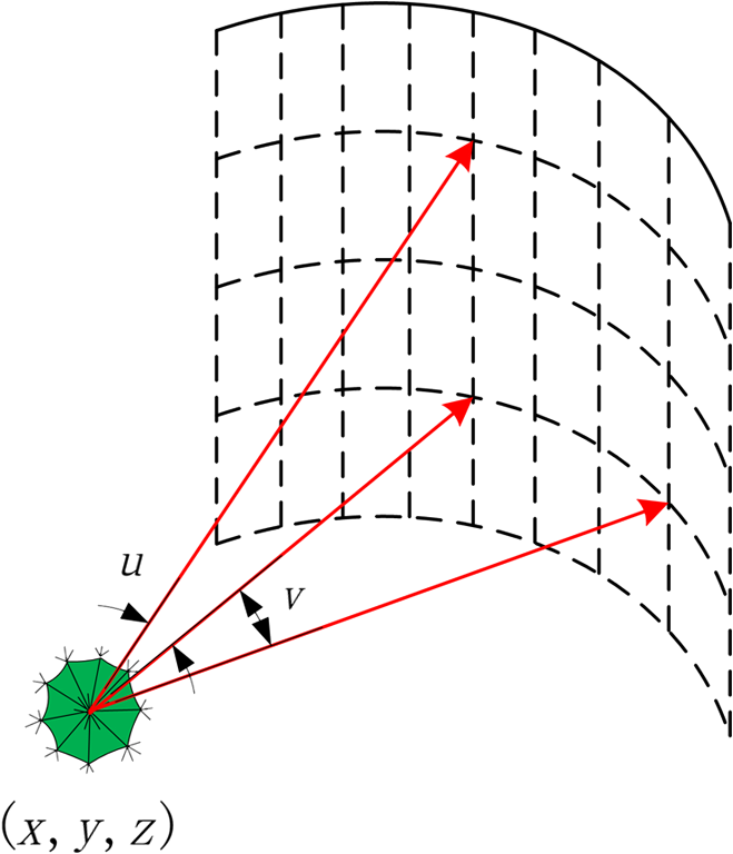
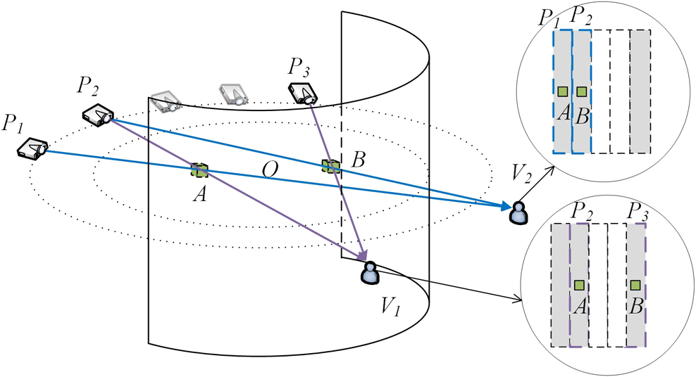
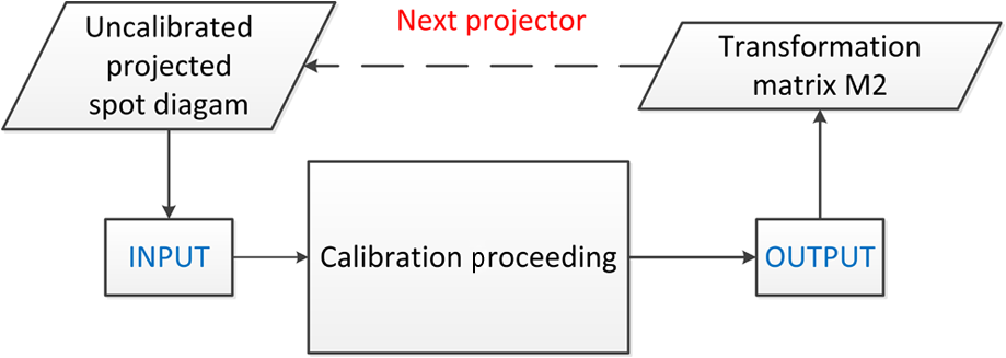
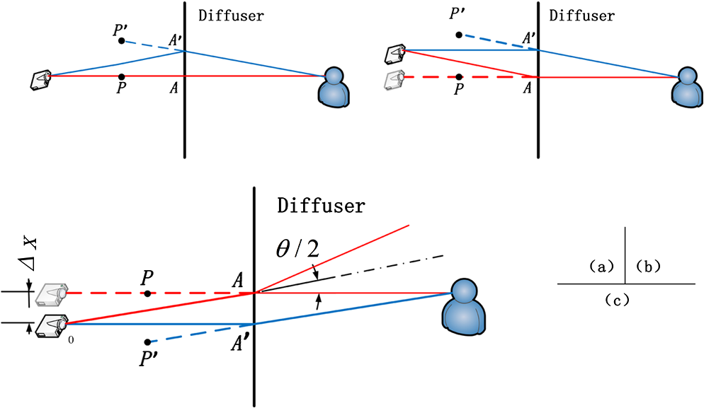
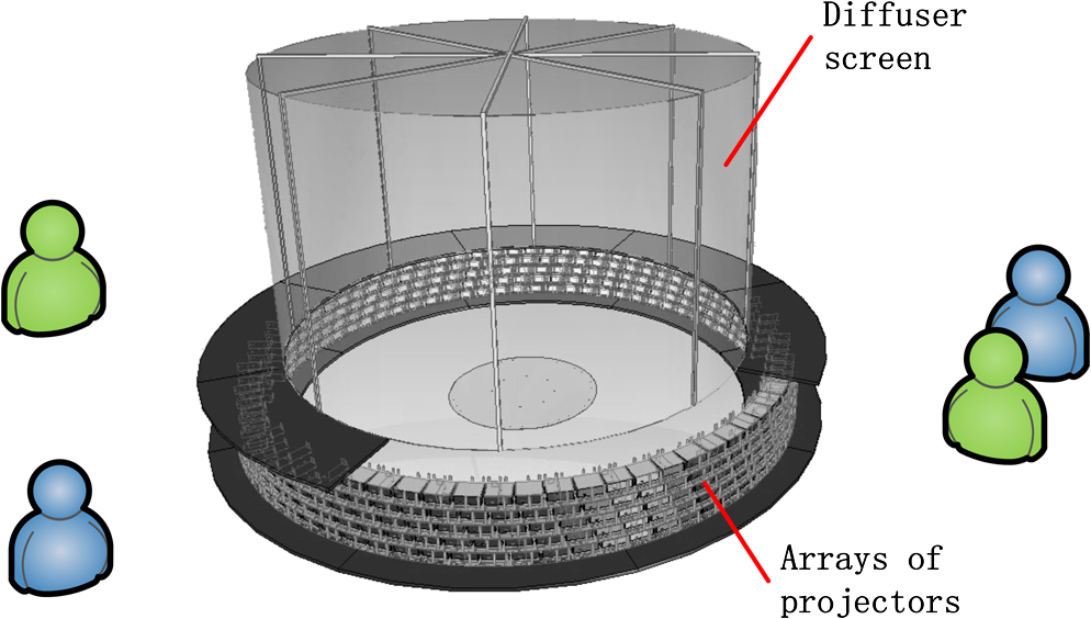
1.IntroductionRecent years have witnessed the promising development of three-dimensional (3-D) display techniques.1,2 Levoy and Hanrahan proposed a light field (LF) rendering technique for three-dimensional (3-D) scene reconstruction.3 The major idea is a representation of the LF, which aims to reconstruct the LF of a 3-D scene in a pixel-based rather than a view-based perspective through designed imaging process. Compared to other conventional methods, it generates a higher density of viewing zones such that it provides observers a more comfortable viewing experience. Substantial efforts have been conducted to achieve a 3-D display using LF rendering. A Hungarian company named Holografika proposed the first commercial LF display system.4 Researchers from MIT proposed several display prototypes using multilayer attenuators.5,6 Zhejiang University proposed a liquid-crystal-display-based LF 3-D display system.7 Moreover, Samsung announced a large-scale system using 300 projectors in the 2013 Society for Information Display technical symposium.8 From this, it can be concluded that a large-scale system employed with multiprojections is becoming the trend of 3-D display and has commercial prospects. In a multiprojector-type 3-D display, geometrical calibration is definitely crucial in adjusting the projection accuracy. Alternative methods have been proposed for two-dimensional (2-D) image calibration.9–12 Mainstream methods mentioned in the references are derived from a combination of a standard camera and several uncalibrated projectors, by which excellent calibration results have been achieved. However, our previous studies mainly focus on calibrating a projected image onto a 2-D plane, for example, making one or more projectors display a stitched and undistorted image on a surface of unknown geometry.13–15 Meanwhile, there are few reports in the literature of flexible and efficient calibration dedicated for multiprojector-type 3-D displays so far. Different from the calibration of a 2-D image, the light rays in a 3-D scene are considered as vectors such that projected images are interpreted as a combination of vectors. Therefore, the calibration in multiprojector-type LF 3-D display requires that more factors be taken into consideration. Moreover, it shall be implemented more accurately and efficiently by taking the integral imaging process into consideration. In this study, an automatic geometrical calibration framework for a multiprojector-type LF 3-D display is investigated. Different from the conventional methods, a precise rotary table is added into the calibration framework to enable the usage for a large panoramic viewing angle with a large-scale curved screen. Together with the robust calibration algorithm, which transfers the calibration of a 3-D scene into the calibration of a 2-D image on the diffuser interface, the display performance can be calibrated automatically and accurately. The experimental results verify the effectiveness of the proposed calibration framework. Given that the properties of rays have been taken into consideration, we believe that the calibration algorithm can be applied to most projector-type 3-D displays, not only based on LF reconstruction, but also on a multiview reconstruction. 2.Principle of Multiprojector-type LF 3-D DisplayBy convention, rays can be parameterized in a couple of ways in computer graphics.3,16 Here, we configure it by a point (, , and ) and a direction as Fig. 1 shows. We define the LF rendering of an object in the following form using homogeneous coordinates: When trying to reconstruct the light filled rendering of an object by multiprojection or other techniques, it is important to guarantee the accuracy of the parameters. Figure 2 shows a general configuration of a multiprojectors-type LF display, which consists of a series of projectors arranged in a circle and a directional diffuser. Images are projected upward to the opposite side of the screen with the same height. Because of the angle-interval between the projectors, the special diffuser provides a large diffuse angle in the vertical direction for image perspective, while providing a small angle in the horizontal direction for pupil jointing.17 The vertical diffuse angle of the diffuser depends on the interval angle between the adjacent projectors. Consequently, observers will see the jointed stripe images as Fig. 2 shows. At viewing points and , the two spatial points and are represented by light rays emitted from different projectors and can be seen at different positions. By adding sufficient projectors with appropriate intervals, the stripe images will join together to make up an integral image.18 3.Framework of Geometrical CalibrationThe image generation algorithm for the display system is deduced under a theoretical situation. In reality, as the number of projectors increases, the installation and adjustment of all projectors become a huge task. It is rather difficult and inefficient to calibrate each projector manually and separately. If any projector is not adjusted well, it results in additional distortion and a defective 3-D reconstruction. To solve this problem, our research has been conducted on automatic geometrical calibration. Taking one projector as an example, the framework of geometrical calibration is presented below. First, capture the printed standard spot diagram (s-image) and the projector spot diagram (p-image), and calculate the mapping relationship Matrix 1 () between the p-image in the camera space and the original spot diagram (o-image) in the projector space The calibrated spot diagram (c-image) in the projector space can be obtained by multiplying the s-image with Matrix 1 Then calculate the mapping relationship Matrix 2 () between the o-image and c-image A transformation matrix is then applied for any image generated from the LF rendering algorithm for the projector. This calibration approach can be naturally extended to a system containing many projectors. Repeat this process for every projector and all projections in the system will finally have a uniform standard. Without loss of generality, the main module of autocalibration can be summarized as Fig. 3 shows. Figure 4 presents the captured photos taken during the calibration proceeding mentioned above. The spot diagram in Figs. 4(a) and 4(b) is identified and marked with red circles during image processing. Also, Figs. 4(c) and 4(d) are the spot diagram in the projector space before and after the calibration. Fig. 4Pictures taken in calibration proceeding: (a) s-image, (b) p-image, (c) o-image, and (d) c-image. 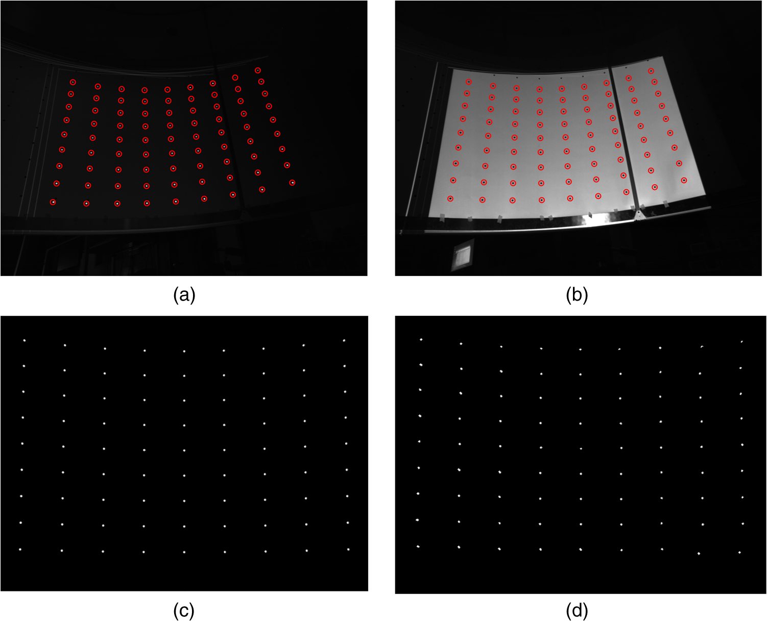 The validity of this method can be demonstrated through discussing several different scenarios. Without loss of generality, the deviation of the projector is divided into two main types, angle deviation and position deviation. 3.1.Angle DeviationWe interpret the projected image as a combination of vectors. Due to the display principle illustrated in the above paragraphs, the image observed at any viewing position is derived from certain rays emitted from a series of projectors. On the other hand, the voxel in the constructed 3-D scene is also composed of rays from different projectors. If one projector is fixed in the right place, what is left is projecting a correct image onto the correct place in a fixed 2-D plane. In Fig. 5, the solid lines represent the practical light rays projected from projectors, and the dashed lines represent the extension of rays connecting the viewing position to a virtual 3-D voxel. Note that herein blue lines stand for the incorrect rays before calibration, while red lines stand for the correct rays after calibration. As Fig. 5(a) shows, we assume a projector is placed at the correct place but toward an incorrect direction. In the diffuser interface, the pixel of the projection image which should be located at is wrongly located at . Also, the observer will see an incorrect voxel from this projector, resulting in the observer seeing an incorrect 3-D scene. The major idea behind the calibration framework is to calculate the mapping relationship between and and assign the information of light ray back to OA. In this way, the incorrect voxel p′ will be replaced with the correct voxel , and a correct projection image can be regenerated after calibration. 3.2.Vertical and Horizontal Position DeviationsFigure 5(b) shows the case of position deviation in the vertical direction. This algorithm also works because of the large diffuse angle in the vertical direction. The observer will see the correct voxel after calibration. In case there is a horizontal position deviation for the projector as shown in Fig. 5(c), we can tolerate half of a horizontal diffuse angle deviation of the projector horizontal position when considering the horizontal diffusing property. Through calculating the mapping relationship between and and assigning the information of light ray back to OA, the observer still can see the correct voxel and obtain the correct 3-D scene provided by this projector. In other words, in this proposed system, the maximum tolerable horizontal position deviation is given by where stands for the distance between the projector and diffuser and stands for the horizontal diffuse angle of the diffuser. In our experiments mentioned below, is 24.7 mm when equals to 1 deg. Without loss of generality, we can limit the horizontal position deviation within 20 mm in the manufacturing operation. Therefore, the horizontal position deviation has relatively less effect on the system.In conclusion, the proposed calibration algorithm transfers the calibration of 3-D scenes into the calibration of a 2-D image in the diffuser interface, which makes it easier to solve. 4.Experiments and ResultsTo verify the principle and calibration algorithm, a prototype is constructed as Fig. 6 shows, which consists of a series of circularly arranged projectors and a cylindrical directional diffuser. All projectors are arranged in a circle under the diffuser and staggered horizontally to condense the pupil array. The specifications are shown in Table 1. Table 1Specifications of the 360 deg display system.
As Fig. 7 shows, the calibration prototype system used in the experiment employs a precise rotary table set in the center. Meanwhile, a CCD camera is fixed onto the table and a printed standard spot diagram is pasted on the diffuser interface. To be clear, the printed standard spot diagram is generated from the LF reconstruction algorithm based on an ideal prototype. Fig. 7Structure of an automatic calibration system: 1. diffuser; 2. printed standard spot diagram; 3. projects array; and 4. CCD camera fixed on precise rotary table.  Figures 8 and 9 show the comparison of the projected spot diagram before and after the calibration. Figures 8(b) and 8(d) are the partial zoomed views of Figs. 8(a) and 8(c). The autocalibration result of spot diagram is illustrated in Fig. 8(d), which is much better than the result for the manual adjustment showed in Fig. 8(c). Fig. 8Comparison of projected spot diagram before and after calibration: (a) projected spot diagram before calibration, (b) partial zoomed views of (a), (c) projected spot diagram after calibration, (d) partial zoomed views of (c). 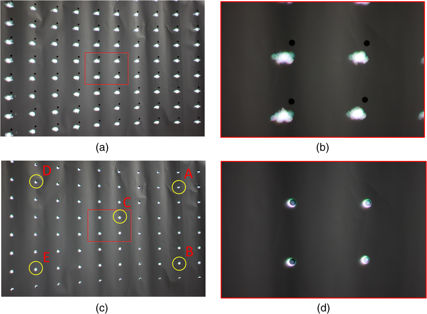 Fig. 9Comparison of projected three-dimensional scene before and after calibration: (a–b) viewed from left position, (c–d) viewed from center position, (e–f) viewed from right position. 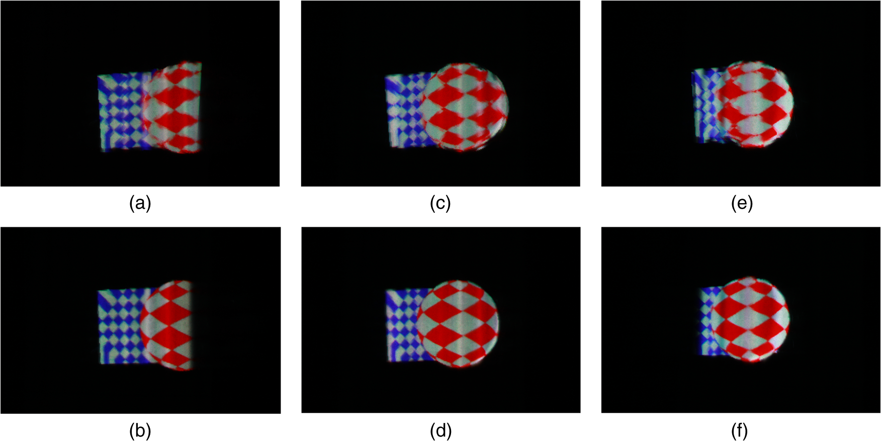 To prove the effectiveness of the calibration framework, we take five spots in different areas marked with yellow circles in Fig. 8(c) to perform the calculation. The calibration accuracies of the spots are listed in Table 2. From the measurement result, the maximum mean deviation is 0.575 pixels. Table 2Measurement calibration accuracy analysis.
Figure 9 shows that a better 3-D scene is achieved after calibration from the left, center, and right viewing positions, which proves the effectiveness of the calibration framework. Figures 9(a), 9(c), and 9(e) are the projected 3-D scene before calibration viewed from the left, center, and right view positions, respectively. Figures 9(b), 9(d), and 9(f) are the projected 3-D scene after calibration viewed from left, center, and right view positions, respectively. The performance enhancement is obvious. 5.ConclusionThis paper presents an automatic geometrical calibration approach for a multiprojector-type LF 3-D display. The calibration framework is proposed and then detailed for calibrating the geometrical deviation and distortion of a projected 3-D scene. Experimental results demonstrate that the projectors in the display system can be adjusted automatically and accurately. The validity of this method has been discussed and we argue that this approach has the robustness to be extended to most existing multiprojector-type displays. Therefore, with the aid of this automatic geometrical calibration, multiprojector-type LF 3-D displays will see great potential in commercial applications in the near future because of its better performance and easier calibration. AcknowledgmentsThis work is supported by research grants from the National Basic Research Program of China (973 Program) (2013CB328802), National High Technology Research and Development Program of China (2012AA011902), and the National Natural Science Foundation of China (61177015). Great thanks to the State Key Laboratory of Modern Optical Instrumentation, Zhejiang University, for providing the necessary support. Also, we thank Yifan Peng from the Department of Computer Science, University of British Columbia, for providing fruitful support. ReferencesJ. Honget al.,
“Three-dimensional display technologies of recent interest: principles, status, and issues [Invited],”
Appl. Opt., 50
(34), 87
–115
(2011). http://dx.doi.org/10.1364/AO.50.000H87 APOPAI 0003-6935 Google Scholar
N. S. Hollimanet al.,
“Three-dimensional displays: a review and applications analysis,”
IEEE Trans. Broadcast, 57
(2), 362
–370
(2011). http://dx.doi.org/10.1109/TBC.2011.2130930 IETBAC 0018-9316 Google Scholar
M. LevoyP. Hanrahan,
“Light field rendering,”
in Proc. of the 23rd Annual Conf. on Computer Graphics and Interactive Techniques,
(1996). Google Scholar
T. BaloghP. T. KovácsZ. Megyesi,
“Holovizio 3D display system,”
in Proc. of the First Int. Conf. on Immersive Telecommunications,
(2007). Google Scholar
G. Wetzsteinet al.,
“Layered 3D: tomographic image synthesis for attenuation-based light field and high dynamic range displays,”
ACM Trans. Graphics, 30
(4), 017402
(2011). http://dx.doi.org/10.1145/2010324 ATGRDF 0730-0301 Google Scholar
D. Lanmanet al.,
“Polarization fields: dynamic light field display using multi-layer LCDs,”
ACM Trans. Graphics, 30
(6), 186
(2011). http://dx.doi.org/10.1145/2070781 ATGRDF 0730-0301 Google Scholar
Y. Penget al.,
“Liquid-crystal-display-based touchable light field three-dimensional display using display-capture mapping calibration,”
Appl. Opt., 51
(25), 6014
–6019
(2012). http://dx.doi.org/10.1364/AO.51.006014 APOPAI 0003-6935 Google Scholar
J. Parket al.,
“48.2: light field rendering of multi-view contents for high density light field 3D display,”
in SID Symposium Digest of Technical Papers,
(2013). Google Scholar
B. SajadiA. Majumder,
“Auto-calibration of cylindrical multi-projector systems,”
in Virtual Reality Conf. (VR), 2010 IEEE,
(2010). Google Scholar
R. Yanget al.,
“Toward the light field display: autostereoscopic rendering via a cluster of projectors,”
IEEE Trans. Visual. Comput. Graphics, 14
(1), 84
–96
(2008). http://dx.doi.org/10.1109/TVCG.2007.70410 TVCG 1077-2626 Google Scholar
Y. Chenet al.,
“Automatic alignment of high-resolution multi-projector display using an un-calibrated camera,”
in Proc. of the Conf. on Visualization’00,
125
–130
(2000). Google Scholar
A. RaijM. Pollefeys,
“Auto-calibration of multi-projector display walls,”
in Proc. of the 17th Int. Conf. on Pattern Recognition, 2004 (ICPR 2004),
(2004). Google Scholar
R. Raskaret al.,
“Multi-projector displays using camera-based registration,”
in Proc. Visualization’99,
161
–522
(1999). Google Scholar
H. Chenet al.,
“Scalable alignment of large-format multi-projector displays using camera homography trees,”
in Proc. of the Conf. on Visualization’02,
339
–346
(2002). Google Scholar
J. Zhouet al.,
“Multi-projector display with continuous self-calibration,”
in Proc. of the 5th ACM/IEEE Int. Workshop on Projector camera systems,
(2008). Google Scholar
L. McMillanB. Gary,
“Plenoptic modeling: an image-based rendering system,”
in Proc. of the 22nd Annual Conf. on Computer Graphics and Interactive Techniques,
(1995). Google Scholar
Y. Penget al.,
“Large-sized light field three-dimensional display using multi-projectors and directional diffuser,”
Opt. Eng., 52
(1), 017402
(2013). http://dx.doi.org/10.1117/1.OE.52.1.017402 OPEGAR 0091-3286 Google Scholar
Q. Zhonget al.,
“Multiview and light-field reconstruction algorithms for 360° multiple-projector-type 3D display,”
Appl. Opt., 52
(19), 4419
–4425
(2013). http://dx.doi.org/10.1364/AO.52.004419 APOPAI 0003-6935 Google Scholar
BiographyBei-shi Chen received his BS degree in information engineering from Zhejiang University, China, in 2012. Currently, he is studying for his MS degree in State Key Laboratory of Modern Optical Instrumentation, Zhejiang University. His research interests include three-dimensional imaging acquisition and display and display characteristic testing. Qing Zhong received his BS degree in information engineering from Zhejiang University, China, in 2011. Currently, he is studying for his PhD degree at the State Key Laboratory of Modern Optical Instrumentation, Zhejiang University. His research interests include projection techniques, three-dimensional display, and display characteristic testing. Hai-feng Li received his BA and MS degrees in physics from Nankai University in 1988 and 1991, respectively, and his PhD degree in optical engineering from Zhejiang University, China, in 2002. He is a professor in the Department of Optical Engineering, Zhejiang University, China. He has been a faculty member at Zhejiang University since 1991. His current research works include three-dimensional light field display, projection display, and liquid crystal devices. Xu Liu obtained his BS and MS degrees in Zhejiang University, China, in 1984 and 1986, respectively, and his PhD in ENSPMUniversité d’Aix-Marseille III, France, in 1990. Now, he is a professor in the Department of Optical Engineering, Zhejiang University, the director of the State Key Laboratory of Modern Optical Instrumentation, and the executive dean of the Faculty of Information Science of Zhejiang University. He is the vice-chair of the Chinese Optics Society. His research fields are optical thin films and thin film technology, optical precision detection, projection display, and three-dimensional display. |