|
|
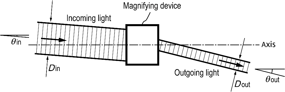
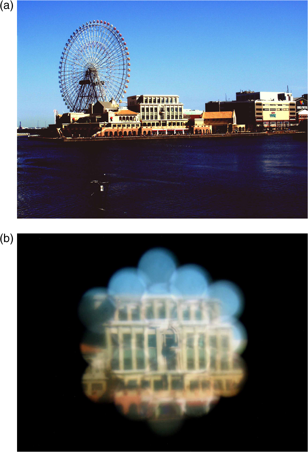
1.IntroductionMagnifying the image of an object is a useful function for assisting human eyes. The most common tool used to magnify the view of an object is a single-convex lens1 if the object is within about 50 cm of the eye. The view of a close object can also be virtually magnified by observing the object from a shorter distance with reading glasses. Reading glasses are convenient because they are light-weight and hands-free. However, neither tool can be applied to magnifying the view of an object which is far from the eye. The ability to magnify the view of a distant object would be convenient, especially for people with poor eyesight. If one’s poor eyesight is due to simple nearsightedness or farsightedness, it is often corrected by using conventional eyeglasses. However, if the poor eyesight is caused by defects in the retina or complicated distortions of the crystalline lens, such as a strong astigmatism, conventional eyeglasses may not be able to recover the eyesight. In such cases, magnifying the image of the object is a practical solution for viewing the object. A well-known tool used to magnify the view of a distant object is a telescope/binocular.2,3 Although binoculars are widely used for a variety of purposes, they are bulky and the viewing area is small unless the volume is extremely large. Therefore, they are not suitable for magnifiers mounted onto eyeglass frames as substitutes for eyeglass lenses. A few designs have been previously proposed for light-weight, hands-free devices for the magnification of distant objects. One example is a design comprising an array of Galileo’s telescope-like lens systems.4 However, the viewing area of this device is limited by geometric aberrations, chromatic aberrations, and structural limits. Another proposed design consists of a small telescope embedded in an eyeglass lens.5,6 The viewing area of this device is limited to only a small portion of the lens. A third proposed design comprises a contact lens with a small, built-in telescope.7 Although this is the most compact design, the use of a contact lens would not be convenient for occasional use. To overcome the limitations described above, a flat-plate magnifier is proposed, designed, and experimentally demonstrated in this paper. The flat-plate magnifiers mounted onto an eyeglass frame as substitutes for the lenses provide a light-weight, hands-free magnifier. Unlike conventional telescopes or binoculars, the flat-plate magnifier can be 3 to 4 mm in thickness and can have a large range of viewing angles. This large angle range allows for a viewing area with a diameter of 30 to 40 mm when mounted onto an eyeglass frame. Using the eyeglasses with this magnifying function, people with poor eyesight can watch TV at a distance as if it were a large screen TV or recognize small objects and writing at a long distance as illustrated in Fig. 1. People with normal vision could also benefit from the flat-plate magnifier since they may more comfortably view an object such as a TV screen, even if the unaided eye has sufficient visual resolution. For viewing a TV screen, it is especially critical that the flat-plate magnifier works over a viewing area that covers the entire screen. Fig. 1Applications of flat-plate magnifiers mounted onto an eyeglass frame for viewing distant objects and watching TV.  In this paper, first, the basic structure and function of the flat-plate magnifier are described. The flat-plate magnifier is a two-dimensional (2-D) array of magnifying modules and each magnifying module consists of two types of components with different functions, which are a micromagnifier and a ray angle adjuster. Next, since the image quality is mainly limited by the micromagnifier, the performance of the micromagnifier is numerically analyzed. Then, the functions of the ray angle adjuster and its combination with the micromagnifier are discussed. Next, using a structure with micromagnifiers and ray angle adjusters, the achromatic condition of the flat-plate magnifier is discussed. Finally, as a prototype, a flat-plate magnifier with a diameter of 9 mm and a magnification power of 3 is demonstrated. 2.Basic Properties of Magnifying DevicesGenerally, an optical device which magnifies the view of an object located at infinity converts traveling angles of light from a small angle into a larger angle. Here, the traveling angle is the angle between the direction of the traveling light and the axis of the magnifying device. Examples of such magnifying devices are a Galileo telescope and opera glasses, which employ a lens system consisting of a positive lens with light converging power and a negative lens with light diverging power. Any structure with an optical device can be a magnifying device if it converts an incoming collimated light beam with a small traveling angle into an outgoing collimated light beam with a larger traveling angle as shown in Fig. 2, provided that is proportional to with a constant coefficient of proportionality. In other words, from the viewpoint of light rays, the condition for a magnifying device is that an incoming light ray with a small traveling angle is converted into an outgoing light ray with a larger traveling angle with a constant coefficient for every ray arriving at any position over the entire area where the light enters. It is noted that tan () is proportional to , if an object is to be seen as being simply enlarged in the transversal direction at the same distance from the eye. This is also considered magnification.8 However, the outer portions of the view are magnified less than the center portion of the view. This is because the eye sees the outer portion of the magnified image from a larger angle than the angle of the corresponding portion in the premagnified view. On the other hand, when is proportional to , every portion of the view is magnified with a constant magnification power. This magnification is considered in this paper. Which magnified image appears more natural is subjective. The flat-plate magnifier proposed in this paper can be designed for either magnification. When a light ray comes from a point in the direction at angle , the eye sees the ray in the direction at angle , and therefore, sees the image of the point in that direction. Since is proportional to , the image of the object is magnified and the magnification power is given by the ratio . All such devices also convert the diameter of a collimated light beam from to as shown in Fig. 2, where is smaller than , and the magnification power is given by the ratio . From the above result, it is expected that both and give the magnification power, therefore, these numbers are equal. The relation is a general property of magnifying devices, regardless of the structure or the mechanism of the device. The validity of this relation can be understood by using beams with rectangular profiles in a 2-D model as described below. For convenience, two collimated light beams with an equal diameter and with a small difference between their traveling angles are considered as the incoming light to the magnifying device. It is assumed that these collimated light beams share the space while traveling in the magnifying device. Assuming that the beam profiles are rectangular, they are in optically orthogonal modes if the optical phase difference between the phases of the two entering light beams changes by across the beam diameter at the device entrance. The beam orthogonality is maintained throughout the magnifying device to ensure the conservation of energy. Therefore, the optical phase difference between the phases of the two exiting light beams also changes by across the beam diameter at the device exit, while the two collimated light beams exiting from the magnifying device have a difference between their traveling angles. This phase change must be , not a multiple of , because the same argument can be made for light beams traveling in the reverse direction. The phase change of is equivalent to a distance of the wavelength in space. With these relations, , and thus, is obtained. Since and are accumulations of and , respectively, is obtained to the extent that remains virtually unchanged. It is noted that if the light is traveling in a medium, the traveling angle, such as and , is considered to be the effective angle, which is larger than the actual angle by a factor of the refractive index of the medium. 3.Structure of the Flat-Plate MagnifierThe flat-plate magnifier proposed in this paper is designed to provide magnification over its entire area. In other words, the condition for magnification, which is , is satisfied by every light ray arriving at any position over the entire area of the flat-plate magnifier. Here, the constant is the magnification power. The structure of the flat-plate magnifier is a 2-D array of magnifying modules, each of which is designed to satisfy the magnifying condition, . Each magnifying module also converts an incoming collimated light beam into an outgoing collimated light beam with a smaller diameter. The details of the magnifying module will be described later. A honeycomb pattern is used for the 2-D distribution of the magnifying modules in this paper. This pattern is an equilateral triangle grid with hexagonal cells, and the magnifying modules arrayed in this pattern are illustrated as the front view in Fig. 3. Each magnifying module covers the hexagonal area and the incoming light entering the light entrance window of this hexagonal area exits as a thinner outgoing light beam. Figure 4 illustrates the side view of four of the magnifying modules positioned along the vertical direction in the array. A collimated light beam enters the magnifying modules. The top figure is with the light beam entering in parallel to the axis of the flat-plate magnifier and the bottom figure is with the light beam entering at an angle , where the axis of the flat-plate magnifier is the axis perpendicular to the plane of the flat-plate magnifier. In the figures, the incoming light beam is illustrated as consisting of four parts, each entering an individual magnifying module. In either figure, the traveling angles of the incoming light rays for all the magnifying modules are equal. Therefore, the ray angles of the outgoing light beams exiting from all the magnifying modules are also equal and are equal to , because the magnifying condition, , is to be satisfied with an equal constant for all the magnifying modules. Fig. 4Side views of an array of magnifying modules for on-axis incoming light (a) and for angled incoming light (b). 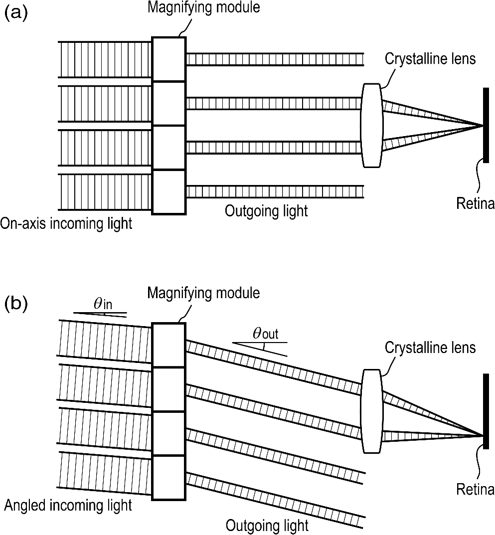 Since the outgoing light beams exiting from all the magnifying modules are parallel to each other, the light arriving at the pupil of an eye is focused by the crystalline lens onto a point on the retina, the position of which is solely determined by . This is true as long as the crystalline lens has no geometric aberration and does not respond to changes of the position at which the light beam enters the pupil. As a result, light originating at a point which is located at infinity is focused onto a point on the retina. This means that the point in the direction effectively subtends to the eye. Figure 4 also shows that there are gaps between the outgoing light beams. However, the gaps do not affect the position of the point on the retina onto which the light is focused, as long as the light travels at the determined by the magnifying condition. As mentioned earlier, each magnifying module in the 2-D array consists of two components, which are a micromagnifier and a ray angle adjuster. The magnification is generated by the micromagnifier, which is a combination of a concave mirror and a convex mirror facing each other. The ray angle adjuster is an optical wedge which is used to expand the viewing area by offsetting the angle of the traveling light. The details of the ray angle adjuster will be discussed later. The structure of the micromagnifier is shown in Fig. 5 and it can be considered a micro-Cassegrain reflector. The magnified image is created through the light converging power of the concave mirror and the light diverging power of the convex mirror. The bold curves in Fig. 5 are mirrors and the concave mirror has a hole in the center. In a typical design, the concave mirror and the convex mirror are parabolic mirrors having a common axis and their focal points are at the same position. The axis of these parabolic mirrors will be referred to as the principal axis of the micromagnifier. The flat surface on the left side of the micromagnifier surrounding the convex mirror is the light entrance window. The flat surface on the right side of the micromagnifier within the hole in the center of the concave mirror is the light exit window. Fig. 5Micromagnifier consisting of a convex mirror and a concave mirror with a Cassegrain reflector-like configuration. 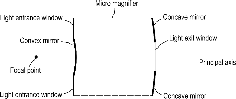 Since micromagnifiers in the flat-plate magnifier form a 2-D array, the array of the micromagnifiers can be realized as a plastic plate with the parabolic mirrors built on the front and the back surfaces. The design used for the prototype has the following parameters. The micromagnifier is 1.8 mm in diameter and 1.8 mm in length. The focal lengths of the concave mirror and the convex mirror are 2.7 and 0.9 mm, respectively. Since the focal length of the concave mirror divided by the focal length of the convex mirror is 3, this design produces a magnification power of 3 and the diameter of the exiting light beam becomes 0.6 mm. With these parameters, the angular resolution of the micromagnifier due to the diffraction limit is comparable to the angular resolution of a healthy human eye, which is about 1 arc min or .9 Considering the angular resolution, the intended application of the flat-plate magnifier is not to observe an object which is too small for a healthy eye to recognize. The flat-plate magnifier will be useful for people with below average visual acuity since they can potentially improve their vision to normal acuity levels using the flat-plate magnifier. People with normal vision could also benefit from the flat-plate magnifier as mentioned earlier. Since the micromagnifier uses internal reflections at the surface of the plastic, chromatic aberration of the micromagnifier is not an issue as long as the entering light beam and the exiting light beam are close to normal to the light entrance window and the light exit window, respectively. The light entrance windows and the light exit windows are anti-reflection coated. In addition, to avoid undesirable reflections of light, the outside (right side in Fig. 5) surfaces of the concave mirrors which face the eye are coated in black. 4.Image Quality Limited by MicromagnifierWhen the object is at infinity, the light beam arriving from the object is collimated. Since the concave mirror and the convex mirror are parabolic mirrors and their focal points are at the same position, a collimated beam entering the micromagnifier parallel to its principal axis exits from the micromagnifier as a collimated beam which is also parallel to the principal axis. Due to the nature of a parabolic mirror, no geometric aberration is generated in the micromagnifier as long as the light beam enters the micromagnifier parallel to the principal axis. If the light beam entering the micromagnifier is collimated but travels at an angle, geometric aberrations will be an issue. If the incoming parallel rays are converted into outgoing rays which are not exactly parallel to each other, the sharpness of the image may be impaired. In conventional telescopes, only rays within a small portion of the eyepiece enter the pupil and, as long as the rays within the pupil are parallel, the sharpness of the image does not suffer. Gradual change of the angles of outgoing rays across the eyepiece will only cause an image distortion. On the other hand, in the micromagnifier, all or most of the light coming from the convex mirror enters the pupil. Therefore, the micromagnifier is more sensitive than a conventional telescope to the geometric aberrations if their angles of the incoming light are equal. An advantage of the flat-plate magnifier is that each micromagnifier receives only light within small entering angles. In order to create a sharp image, it is important that all the outgoing rays exiting from the micromagnifier are nearly parallel to each other. To ensure sharpness of the image, deviations of angles of the light rays exiting from the micromagnifier are numerically analyzed when the light rays entering the micromagnifier are parallel to each other. Since the angular resolution of this analysis is high compared to the diffraction caused by a beam size of 0.6 mm, the analysis is carried out using ray tracing. In the actual micromagnifier, the entering rays are partially blocked by the convex mirror near the center of the light entrance window. However, the analysis is carried out as if the entering rays were not blocked by the convex mirror. Similarly, although no mirror is formed in the light exit window area, the analysis is carried out as if the rays in the light exit window area were reflected by the concave mirror. The numerical analysis discussed below is in two dimensions, i.e., both entering rays and exiting rays are in a plane which includes the principal axis of the micromagnifier. The angle of the ray entering the micromagnifier is denoted by and the angle of the ray exiting from the micromagnifier is denoted by , both with respect to the principal axis. First, the relations between the entering position of the ray and the exiting angle are shown in Fig. 6 for three different entering angles , , 0, and . The results indicate that deviations of the exiting angles are less than for the rays arriving at positions over the entire light entrance window, which has a diameter of 1.8 mm, as long as the entering angle is within . Fig. 6Entering position of the ray versus exiting angle of the ray for entering angles of the ray at (a), 0 rad (b), and (c). 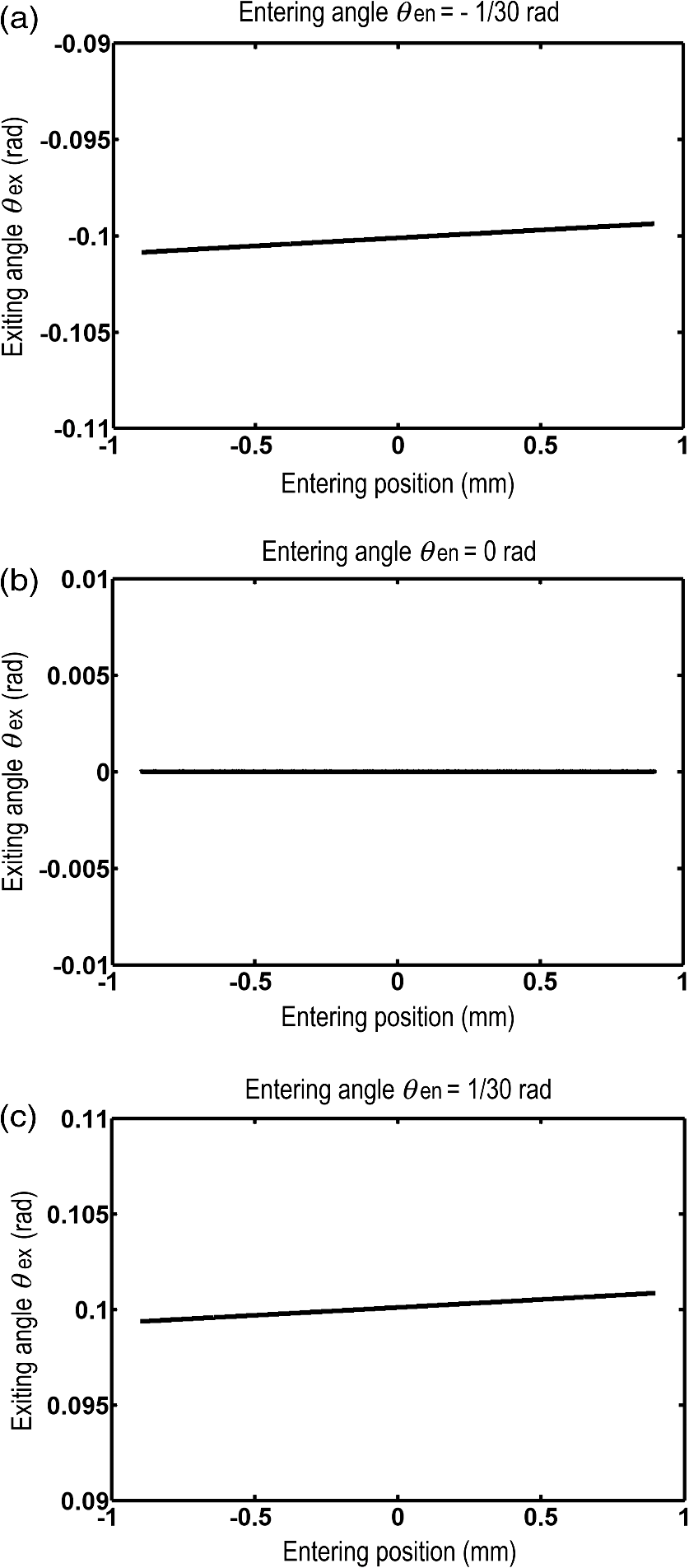 Next, the relations between the entering angle and the exiting angle are shown in Fig. 7 for three different entering positions, , 0, and 0.9 mm, which correspond to one edge, the center, and the other edge of the light entrance window, respectively. The results indicate that the exiting angles are, to a good approximation, proportional to the entering angles with a coefficient of 3, which is the theoretical magnification power of the micromagnifier. Fig. 7Entering angle of the ray versus exiting angle of the ray for entering positions of the ray at (a), 0 mm (b), and 0.9 mm (c). 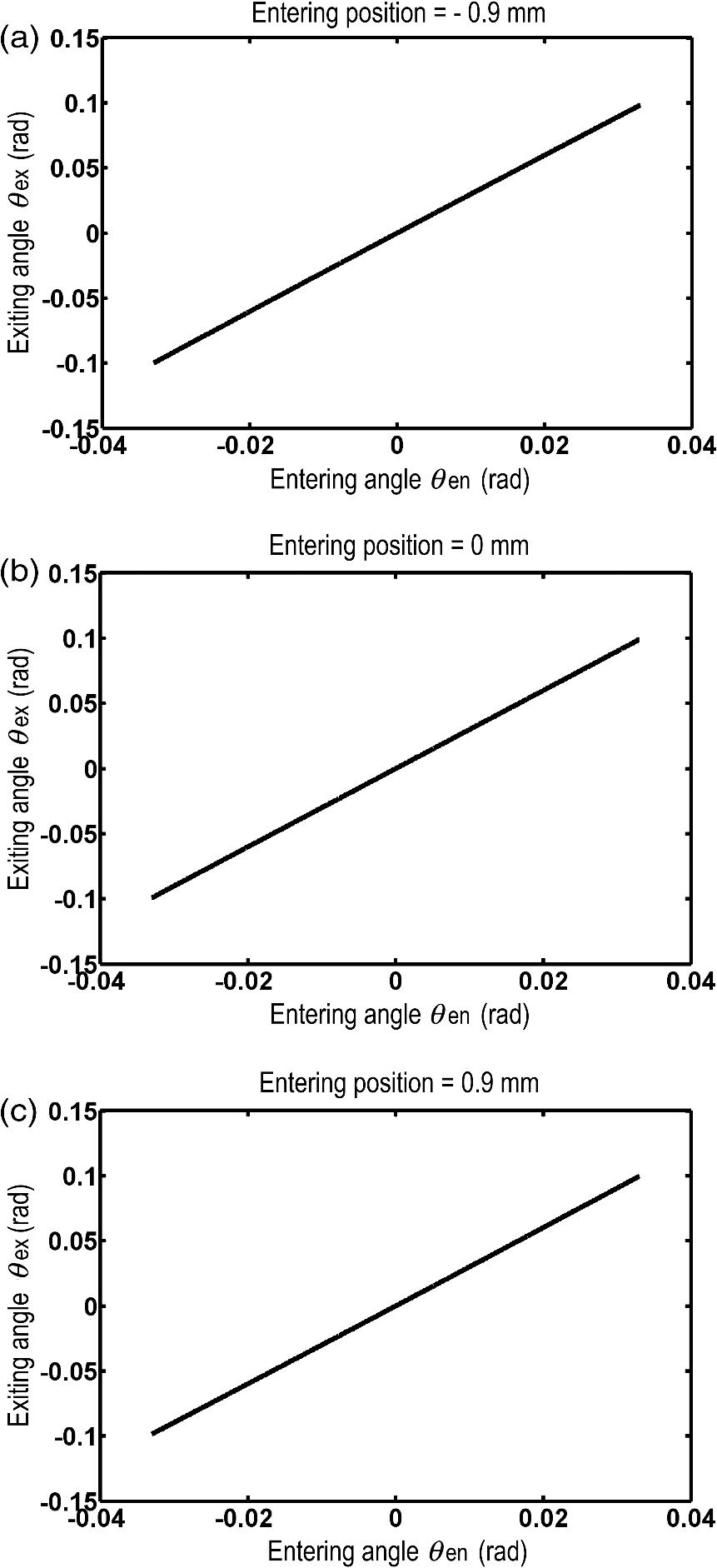 The numerical analysis indicates that the micromagnifier works with little geometric aberration for entering angles within or for exiting angles within 0.1 rad. Geometric aberrations will be generated for light rays out of this angle range, thus, the image created out of this range may not be sharp enough to be used for magnifying devices. As is expected, the ratio of the angle changes, , is 3, as can be seen in Fig. 7. In this numerical analysis, all the entering positions of the rays are in the plane of this 2-D analysis. When the entering angle is not 0, the entering ray is tilted in the plane of this 2-D analysis. It is of interest to discuss the value of when the entering ray is tilted in the same direction as above, but the entering position is out of the plane of this 2-D analysis. To discuss this case, it is assumed that the entering position of the ray is away from the center of the light entrance window in the direction perpendicular to the plane of the 2-D analysis. This ray is the ray of interest in this discussion. The exiting angle of this ray is analyzed as the entering angle changes from 0. First, to first order of , the exiting ray should not be tilted toward or away from the principal axis. Next, the relation between and should be anti-symmetric, when is observed in a plane parallel to the plane of the 2-D analysis. These two results are due to the symmetry of the mirror system. Based on the above symmetry conditions, the value of is discussed at . Again, the micromagnifier consists of two parabolic mirrors of different sizes, which have a common axis and a common focal point. Therefore, the shapes of the mirrors are geometrically similar and they share a focal point. In other words, if the smaller parabola were enlarged by a factor of 3 while keeping the focal point fixed, it would have the same shape and position as the larger parabola. First, the light beam entering in parallel to the principal axis is converted into the exiting light beam and the beam diameter is reduced to , as described before. Next, a small portion of this entering light beam, which is chosen to include the ray of interest, is considered. This small portion of the entering light beam is also converted into a small portion of the exiting light beam and the beam diameter is also reduced to . This result can be obtained from simple geometry using only the nature of parabolic mirrors and the similarity of the mirror shapes described in the paragraph above. Since, to first order, the exiting ray is not tilted toward or away from the principal axis as changes from 0, the general property of magnifying devices, which is , is applied to the small portion of the light beam with . When the small portion of the light beam is made thin enough to be represented by the ray of interest, is obtained. 5.Viewing Area Expanded by Ray Angle AdjustersOne of the advantages of using the flat-plate magnifier is that it provides a large viewing area, especially when mounted onto an eyeglass frame. To provide a large viewing area, the magnifying modules are arrayed in two dimensions with the pattern as shown in Fig. 3. The eye sees an object through many light paths, each of which has passed through one of the magnifying modules. In order for the flat plate magnifier to work, the condition needs to be satisfied by every light ray arriving at any position over the entire area for light entrance of the flat-plate magnifier, as described earlier. Figure 8 shows the light rays traveling from an object plane at a distance to the eye where a light ray passes through each magnifying module and travels to the center of rotation of the eyeball. When the above requirement is met, the images of an object which are seen through different magnifying modules become identical, i.e., a single image is formed. As a result, the magnified images viewed through different magnifying modules are continuously jointed to create the whole image. Fig. 8Light ray paths traveling through the flat-plate magnifier toward the center of rotation of an eyeball.  and are the angles of a light ray before and after traveling through both a micromagnifier and a ray angle adjuster, respectively, and are measured with respect to the axis of the flat-plate magnifier. On the other hand, as discussed in the numerical analysis of the micromagnifier, and are the angles of a light ray before and after traveling through a micromagnifier only, respectively, and are measured with respect to its principal axis. In the magnifying module, the changes of the ray angles, and , are produced by and , respectively. Therefore, it is expected that is satisfied for each magnifying module. Since the mirror configuration is the same for all the micromagnifiers, they have the same values of . With this relation between and for each magnifying module, the flat-plate magnifier works if the following two conditions are met. The first condition is that is satisfied by at least one of the rays in the magnifying module and the second condition is that the first condition is fulfilled for every magnifying module. In Fig. 8, each light ray travels through one of the magnifying modules in the flat-plate magnifier. These light rays are the rays which converge at the center of rotation of the eyeball. The light rays are also illustrated so that each ray passes through the magnifying modules to satisfy the condition, . Each of these rays is the ray discussed as “one of the rays” in the paragraph above. An eye sees an object most acutely through the light ray which strikes the fovea of the retina. This light ray is referred to as the principal ray of the eyeball and the principal ray passes through near the center of rotation of the eyeball. Since the light rays in Fig. 8 converge at the center of rotation of the eyeball, the eye always receives one of these light rays through the pupil, which then becomes the principal ray of the eyeball, even when the eyeball turns around the center of rotation to see over a wide angle. In order for the flat plate magnifier to work with a large viewing area, the magnifying modules at off-center positions must receive the light rays traveling at large angles with respect to the axis of the flat-plate magnifier, while these light rays pass through the magnifying modules with few geometric aberrations. The maximum viewing angle considered in this paper, which is the maximum in Fig. 8, is about 0.5 rad or 28 deg from the center. Therefore, at off-center positions obviously exceed the maximum limit of 0.1 rad for the exiting angle of a micromagnifier itself, which was mentioned in the numerical analysis. Therefore, a micromagnifier itself cannot receive light rays with such large angles and still create a sharp image. When the flat-plate magnifiers are mounted onto an eyeglass frame, the relative positions of the magnifying modules with respect to the eyeballs are fixed. Therefore, even though a magnifying module at an off-center position of the flat-plate magnifier receives the light rays at large angles, the traveling angles of all the light rays entering that magnifying module are within a small range around the traveling angle of the ray illustrated in Fig. 8. With this fact, each of the light rays illustrated in Fig. 8 is made to travel through the micromagnifier in parallel to its principal axis by tilting the micromagnifier and offsetting the ray angle using a ray angle adjuster. Here, the ray angle adjuster is introduced. It is a wedge-shaped piece of plastic and it changes the ray angles through refraction. With the ray angle adjuster, all the light rays entering a micromagnifier travel at small angles with respect to its principal axis and the geometric aberrations are suppressed. In other words, each magnifying module serves a small viewing area, resulting in low geometric aberrations. When the small viewing areas provided by the magnifying modules are combined, a large viewing area is provided with low geometric aberrations. Thus, properly designed ray angle adjusters expand the viewing area of the flat-plate magnifier while keeping a sharp image. The size of the viewing area is limited by the maximum viewing angle and the viewing angle is limited by the maximum possible wedge angle of the ray angle adjuster. The possible viewing angle allows for a viewing area of 30 to 40 mm in diameter when mounted onto an eyeglass frame. Since ray angle adjusters in the flat-plate magnifier form a 2-D array and each ray angle adjuster is a plastic wedge, the array of the plastic wedges can be realized as a plastic plate with the refraction facets built on the front and the back surfaces. Both surfaces are anti-reflection coated. This plastic plate with the 2-D array of ray angle adjusters is placed adjacent to the plastic plate with the 2-D array of the micromagnifiers so that each pair of a micromagnifier and a ray angle adjuster forms a magnifying module. The side view of the flat-plate magnifier along a cross section is shown in Fig. 9. The micromagnifiers are tilted so that the light rays that were illustrated in Fig. 8 pass through the micromagnifiers in parallel to their principal axes. In Fig. 9, is the tilting angle of the micromagnifier and and are the angles of the light entrance facet and light exit facet of the ray angle adjuster, respectively. These angles are measured toward the outer direction with respect to the axis of the flat-plate magnifier. When a micromagnifier is tilted, the light exit window of the micromagnifier is also tilted by . However, the light entrance window of the micromagnifier is not tilted in the design of Fig. 9, and the light entrance windows of all the micromagnifiers form a flat plane. 6.Magnified Image Seen by EyeAs seen in Figs. 3 and 4, each outgoing light beam from a magnifying module has a smaller diameter than the diameter of the magnifying module by the ratio of the magnification power. Therefore, there are gaps between adjacent outgoing light beams when observed in the plane perpendicular to the light traveling direction. The outgoing light beams travel to the crystalline lens and focus onto a point on the retina. However, if the pupil should fall into one of the gaps, no light enters the pupil and the eye cannot see the object. To prevent that from happening, it is important that the gaps between the outgoing light beams in the above-mentioned observation plane be made smaller than the size of the pupil. This requirement determines the maximum period of the magnifying modules in the array. The diameter of the magnifying module in this paper is 1.8 mm, which effectively makes the maximum gap between the adjacent light beams 1.5 mm. With this gap size, an average eye can see the magnified image of an object without significant interruptions. This will be shown later in Fig. 13 as the experimental result. On the rare occasions that the effective pupil becomes small due to an obstacle in the light path, such as a defect in the crystalline lens, the gaps may become noticeable and the flat-plate magnifier may not work as designed. It is noted that the brightness of a magnified image seen by an eye through the flat-plate magnifier is lower than that of the actual view of the object. This is because, even if no optical loss is assumed through the flat-plate magnifier, the spatial average of light energy before and after the flat-plate magnifier remains the same. Therefore, the light energy entering the pupil is unchanged by inserting the flat-plate magnifier, while the image is magnified. Thus, the same amount of light energy is distributed over the magnified image on the retina and the energy density becomes lower. For a flat-plate magnifier with a magnification power of 3, the density of the light energy will become one ninth. In addition to the effect described above, there will be some optical losses. First, using the honeycomb pattern of the magnifying modules, the light entrance windows of the micromagnifiers cover the light entrance side of the flat-plate magnifier almost seamlessly except the areas with the convex mirrors. These areas with convex mirrors block part of the incoming light and cause an optical loss for the flat-plate magnifier. Next, when the angle of a light beam entering the micromagnifier increases beyond a certain angle, the exiting light beam could be partially blocked by the concave mirror at the light exit window. This also causes an optical loss for the flat-plate magnifier. The optical loss due to these blocked light beams is estimated to be about 25% to 35%. When the three factors described above are combined, the brightness of the image with the flat-plate magnifier will effectively be about 8%, which is in the range of sunglasses. Therefore, the flat-plate magnifier is suitable for seeing bright views or objects with a background that is darker than the objects. 7.Parameters for Practical DesignThere are a variety of sets of design parameters for the flat-plate magnifier. The parameters for an off-center magnifying module are calculated by tracing a particular light ray. To discuss the parameters, a micromagnifier and a ray angle adjuster along the particular ray are illustrated in Fig. 10. This particular ray, which is the ray of interest in this discussion, is the light ray traveling through the micromagnifier in parallel to its principal axis. Therefore, the ray of interest in Fig. 10 becomes each of the light rays in Fig. 8. Fig. 10Traveling angle changes along the light ray through the micromagnifier and the ray angle adjuster.  The micromagnifier and the ray angle adjuster are designed for the ray of interest to satisfy the condition . In the calculations below, the angle of the incoming ray is denoted by and the angle of the outgoing ray is denoted by for the magnifying module. In addition, is the tilting angle of the micromagnifier, is the wedge angle of the ray angle adjuster, and are the angles of the ray after the entrance window and before the exit window of the micromagnifier, respectively, is the angle of the ray between the micromagnifier and the ray angle adjuster, and is the angle change of the ray through refraction of the ray angle adjuster. All the angles except and are measured with respect to the axis of the flat-plate magnifier. In the design which was used for the prototype, all the light entrance windows of the micromagnifiers form a plane. Therefore, the light entrance window of an off-center micromagnifier is angled by with respect to the principal axis of that micromagnifier. Since all the rays pass through the micromagnifier nearly in parallel to its principal axis, these rays pass through the light entrance window at an angle, resulting in refraction of the rays. As a result, when the angle of the incoming light ray varies, the changes of the effective ray angle between before and after the refraction are not equal. In other words, the ratio of the changes of the angle is not 1. This could cause an image distortion in that direction. However, in the design described below, this ratio is estimated to be 1.0086 even for an outer micromagnifier corresponding to in Fig. 8. Therefore, the image distortion due to this effect is small and can be neglected. It is theoretically possible to precisely cancel this image distortion with the ray angle adjuster, as will be discussed later. The tilting angle of the micromagnifier , the wedge angle , and all other angles for an off-center magnifying module shown in Fig. 10 are determined as a function of , which is the distance of that magnifying module from the center axis of the flat-plate magnifier. is the distance of the magnifying module from the center line in Fig. 9 and is also the radius from the center in Fig. 3. The distance between the flat-plate magnifier and the center of rotation of the eyeball in Fig. 8 is fixed at 30 mm in this paper. Then, is determined by Eq. (1): Since a magnification power of 3 is chosen for the prototype, by definition. The refractive index of the plastic in the micromagnifier is denoted by . Then, the angle of the ray is changed from to by refraction at the light entrance window and is determined by Eq. (2): Since the ray of interest travels through the micromagnifier in parallel to the principal axis of that micromagnifier, it is obvious that . Next, regarding the symmetry of the wedge of the ray angle adjuster, it is designed so that the light path in the wedge is perpendicular to the plane that bisects the wedge. The refractive index of the plastic in the wedge is denoted by . Then, the wedge angle is determined to satisfy Eq. (3): In Eqs. (2) and (3), and can be chosen from the refractive indices of plastic materials that are practical for the molding processes. The freedom of choosing these numbers will be used later along with the Abbe numbers to satisfy the condition for achromatic dispersion. Using the , which is determined by Eq. (3), the angles of the light entrance facet and the light exit facet of the ray angle adjuster, and , are calculated by Eqs. (4) and (5), respectively: Here, and are the angles with respect to the axis of the flat-plate magnifier and they are measured toward the outer direction. As mentioned earlier, the ratio of the changes of the ray angle between before and after refraction at the light entrance window of the micromagnifier is, at most, 1.0086. Again using the general property of magnifying devices, , it is noted that the diameter of the light beam is changed by a factor of through refraction at the light entrance window. In the above design with Eqs. (4) and (5), the wedge of the ray angle adjuster had a particular symmetry with respect to the light path so that the diameter of the light beam was not changed by the wedge. Therefore, a small distortion of the image is estimated but it can be neglected. It is theoretically possible to precisely cancel this image distortion, which is caused by the angled entrance window, with the ray angle adjuster as described below. If the diameter of the light beam is changed by a factor of 1.0086 by placing the wedge slightly asymmetrically with respect to the light path, the image distortion due to refraction at the angled entrance window is perfectly cancelled by the ray angle adjuster. This condition is equivalent to the condition that, with the refraction at both the micromagnifier and the ray angle adjuster taken into account, the diameter of the outgoing light beam is exactly of the diameter of the incoming light beam. 8.Condition for Achromatic DispersionThe light ray travels through the entrance window of the micromagnifier and the facets of the ray angle adjuster, each time at an angle, except for the center magnifying module. Therefore, the traveling angle of the light varies with the wavelength due to the chromatic dispersion of the plastic. This causes chromatic aberration, which is an angular dispersion of when the angle of the incoming ray is fixed. However, this angular dispersion can be suppressed by choosing the design parameters so that the angular dispersion at the light entrance window of the micromagnifier is cancelled by the angular dispersion from the ray angle adjuster. The condition for achromatic dispersion is for a fixed . To analyze the angular dispersions, the micromagnifier with the angled entrance window shown in Fig. 10 is considered as consisting of two parts, which are an entrance window wedge and a micromagnifier with a normal entrance window, as shown in Fig. 11. First, the chromatic angular dispersion of the ray at the entrance window wedge, , due to the wavelength dependent is shown in Eq. (6): Next, the chromatic angular dispersion of the ray at the ray angle adjuster wedge, , due to the wavelength dependent is shown in Eq. (7): Chromatic angular dispersion at the entrance window wedge is enhanced by the micromagnifier by a factor of 3, which is the magnification power. Therefore, the condition for achromatic dispersion is given by Eq. (8): Using the Abbe numbers of the plastic materials, and , which are for the micromagnifier and for the ray angle adjuster, respectively, Eq. (9) is given Combining Eqs. (8) and (9), the condition for achromatic dispersion is rewritten as Eq. (10): First, practical plastic materials for the micromagnifier and the ray angle adjuster are chosen so that , , , and satisfy Eq. (10). In this calculation, the magnifying module at the seventh position from the center was used to represent the off-center magnifying modules. One of the sets of these four quantities among practical plastic materials is as follows. The refractive index of the micromagnifier is and its Abbe number is . The refractive index of the ray angle adjuster is and its Abbe number is . Since all the micromagnifiers form a plastic plate, they are made of the same plastic material. All the ray angle adjusters form a separate plastic plate and their plastic materials are the same. Using these two plastic materials, the design parameters for every magnifying module are calculated with the above values of and using Eq. (1) through Eq. (5). For example, the design parameters for the seventh magnifying module are , , , , , and . These parameters for this particular magnifying module satisfy the achromatic condition, Eq. (10), by design. Next, it is shown that the parameters calculated for other magnifying modules, which have different values, also approximately satisfy Eq. (10). is approximately proportional to as shown in Eq. (2). Therefore, both and are approximately proportional to as shown in Eq. (3). Since both the numerator and the denominator of the left-hand side of Eq. (10) are approximately proportional to , the left-hand side of Eq. (10) shows little change as varies as long as is not large. Thus, once Eq. (10) is satisfied for the seventh magnifying module, Eq. (10) is approximately satisfied for other magnifying modules for a practical range of . 9.Fabrication of the Flat-Plate MagnifierAs described above, all the angles in the design are determined to satisfy the condition for the single-image formation and the achromatic condition. In addition to the angles, the diameter of the light exit window in the center of the concave mirror should be larger than of the diameter of the light entrance window. This is because the exiting light from the micromagnifier could be partially blocked by the concave mirror at the light exit window when the light is angled with respect to the principal axis of the micromagnifier and this loss of light should be reduced. Furthermore, the diameter of the convex mirror in the center of the light entrance window should be larger than the diameter of the light exit window. This is because light rays traveling directly from the light entrance window around the convex mirror to the light exit window without being reflected by either mirror becomes stray light. This unwanted light interrupts creation of a clear image and these rays with small traveling angles should be blocked. However, if the convex mirror is unnecessarily large, it causes an extra loss of light. These diameters discussed above determine the size of the area within which the eye should be positioned to suppress geometric aberrations and to prevent the stray light from entering the eye. For the fabrication of the device, these diameters were optimized and this area was about 5 mm in diameter. Stray light is perfectly blocked by positioning the flat-plate magnifier to have the eye within this range. Both the plate with micromagnifiers and the plate with ray angle adjusters were fabricated by plastic molding. For a flat-plate magnifier to create a sharp image, it is important that the mold is precisely formed. Both roughness and distortion of the surface of the mold prevent the flat-plate magnifier from creating a sharp image. Therefore, the mold was carefully formed using a high-precision, multiaxis diamond turning lathe. The mirrors on the plastic were formed by coating with aluminum. Photos of the flat-plate magnifier are shown in Fig. 12. The left photo was taken from the side of the micromagnifiers and the right photo was taken from the side of the ray angle adjusters. The size of each magnifying module with a hexagonal structure is 1.8 mm from side to side. There are 19 magnifying modules in this prototype of the flat-plate magnifier, which are the 19 magnifying modules in the center of Fig. 3. Therefore, the viewing area is about 9 mm from side to side. As can be seen in the photos, the array of micromagnifiers forms a plastic plate and the array of ray angle adjusters forms a separate plastic plate. These plastic plates are put together to form the flat-plate magnifier. The total thickness of the flat-plate magnifier with these plates is 3.6 mm. Fig. 12Photos of the micromagnifiers’ sides (a) and the ray angle adjusters’ sides (b) of the flat-plate magnifier (diameter of the viewing area: 9 mm).  As described earlier, the concave mirrors and the area around them seen from the side of the ray angle adjusters are coated in black. However, they do not look black in the photo taken from the side of the micromagnifiers, because these areas are mirrors on that side. It is preferable to prevent unwanted stray light from entering the flat-plate magnifier through its surfaces. Light could enter the flat-plate magnifier from its side surfaces along the perimeter. In addition, if there are extra areas around the viewing area as it appears in Fig. 12, the light could also enter from these extra surfaces on the eye side and on the object side. Therefore, it is ideal for all these surfaces to be coated in black or to be covered with a light absorptive material. The flat-plate magnifier was tested to observe a distant view. Figure 13 shows the direct view without magnification (a) and the magnified view (b), which was magnified by inserting the flat-plate magnifier. All the surfaces of the flat-plate magnifier except the viewing area were covered with black film as mentioned above. Therefore, the area around the viewing area is dark in the magnified view in Fig. 13. More than 20 samples were produced by plastic molding and all of them showed the same result as those shown in Fig. 13. Therefore, reproduction of the plastic plates in the molding process is precise in terms of the thickness, the parallelism, the relative position, and the relative orientation between their front and back surfaces. Comparing the views in Fig. 13, it is confirmed that the view is magnified with a magnification power of 3 as designed. The magnified view is not sharp compared with the direct view, especially in the outer magnifying modules. In principle, the sharpness of the view should be the same for all the magnifying modules, because all the micromagnifiers have the same mirror configuration and the light passes through these micromagnifiers nearly in parallel to their principal axes. The reason that the magnified view is not sharp enough is not theoretical aberration, but is the insufficient quality of the parabolic surfaces on the plastic plate. Roughness and distortion on the mold are the major causes of insufficient quality. Since the mold was formed by a lathe, the surfaces for outer micromagnifiers are more distorted than those for the center one. Therefore, the views in outer magnifying modules are less sharp. In a separate observation using a single micromagnifier, it was verified that a precisely formed magnifying module created a much sharper view (not shown). The magnified view in Fig. 13 also shows that the angles of the light rays are not precisely adjusted by the ray angle adjusters in some of the magnifying modules. As a result, the images in these magnifying modules are not perfectly continuous with the images in neighboring magnifying modules. It was experimentally verified that for these micromagnifiers were not accurate because these deviated from the designed values due to the distortions of the parabolic surfaces on the mold. 10.Further Design RemarksThe design described in this paper creates the magnified image of an object when the object is located at infinity and the magnified image is also located at infinity. This is because the parabolic concave mirror and the parabolic convex mirror in the micromagnifier have a common focal point. If the object is not at infinity, the mirror spacing or the mirror shapes may be modified. The flat-plate magnifier is suitable to be mounted onto a conventional eyeglass frame. In this application of the flat-plate magnifier, the images of an object for the left eye and the right eye should be at the same position. If the object is at infinity, the center axes of the flat-plate magnifiers for the left eye and the right eye will be in parallel. If the object is not at infinity, these center axes may pass through a point on the object. In an application of the flat-plate magnifiers for mounting onto an eyeglass frame, it is preferable to arrange the flat-plate magnifiers so that the chance of multiple magnifying modules simultaneously overlapping in the views between the left eye and the right eye is reduced. For example, the distribution patterns of the magnifying modules (Fig. 3) for the left and the right flat-plate magnifiers may be relatively rotated with respect to each other around the axis of the flat-plate magnifier. As a particular design, the flat-plate magnifiers are rotated by for the left eye and by for the right eye. This makes a 30-deg difference between the left eye and the right eye, resulting in less interruption of the view caused by the gaps between the light beams. Since each beam diameter of the outgoing light from a micromagnifier is smaller than the diameter of the magnifying module, an optical mask may be formed around the light path on the surface of the ray angle adjuster. The optical mask is a light absorptive mask, such as a black coating or a black film, and helps prevent unwanted stray light from entering the eye. It is also noted that a goggle-like structure, which has side walls, can be used instead of a conventional eyeglass frame to prevent unwanted stray light from entering through the gaps between the viewing window and the face. 11.ConclusionA device for magnifying the image of a distant object was proposed and experimentally demonstrated. Since this device is made in the form of a thin plate, it is considered a flat-plate magnifier. The flat-plate magnifiers mounted onto an eyeglass frame provide a light-weight, hands-free magnifier for viewing distant objects. The flat-plate magnifier is built within a plastic plate with a thickness of 3 to 4 mm and the viewing area can be made up to 30 to 40 mm in diameter. A prototype with a 9-mm diameter was fabricated with a magnification power of 3. It was experimentally confirmed that the flat-plate magnifier magnifies the view in the entire viewing area. ReferencesB. H. Walker,
“Magnifier, or loupe,”
Optical Engineering Fundamentals, 2nd ed.SPIE, Bellingham, Washington
(2009). Google Scholar
B. H. Walker,
“Binoculars,”
Optical Engineering Fundamentals, 2nd ed.SPIE, Bellingham, Washington
(2009). Google Scholar
K. J. Juggins,
“Current products and practice, the bigger the better: can magnification aid orthodontic clinical practice?,”
J. Orthod., 33
(1), 62
–66
(2006). http://dx.doi.org/10.1179/146531205225021420 0301-228X Google Scholar
E. PeliF. Vargas-Martin,
“In-the-spectacle-lens telescopic device for low vision,”
Proc. SPIE, 4611 129
–135
(2002). http://dx.doi.org/10.1117/12.470586 PSISDG 0277-786X Google Scholar
E. PeliF. Vargas-Martin,
“In-the-spectacle-lens telescopic device,”
J. Biomed. Opt., 13
(3), 034027
(2008). http://dx.doi.org/10.1117/1.2940360 JBOPFO 1083-3668 Google Scholar
E. J. Tremblayet al.,
“Switchable telescopic contact lens,”
Opt. Express, 21
(13), 15980
–15986
(2013). http://dx.doi.org/10.1364/OE.21.015980 OPEXFF 1094-4087 Google Scholar
W. J. Smith,
“Telescopes, afocal systems,”
Modern Optical Engineering, 3rd ed.SPIE, Bellingham, Washington
(2000). Google Scholar
W. J. Smith,
“Characteristics of the eye,”
Modern Optical Engineering, 3rd ed.SPIE, Bellingham, Washington
(2000). Google Scholar
BiographyMasataka Shirasaki has over 30 years of research experience in the field of optics, including optical telecommunications and quantum optics. He is the inventor of over 150 patents worldwide, which include an optical isolator, an optical wavelength filter, a chromatic dispersion compensator, a magneto-optic switch, a spectrum analyzer, an optical phase mask, a quantum optic squeezer, and other optical systems. He is also the author of numerous publications in journal papers and conference papers on these topics. Takehiro Kodaira finished his school education in mechanical engineering and joined Nittoh Kogaku K.K. in 1986. His research interests include plastic molding processes. |