|
|
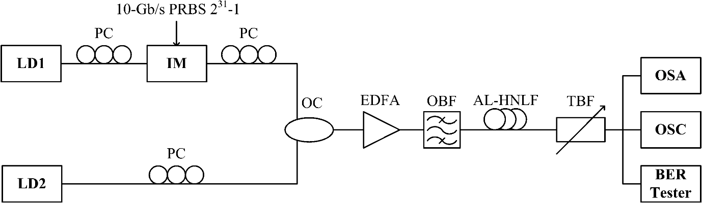
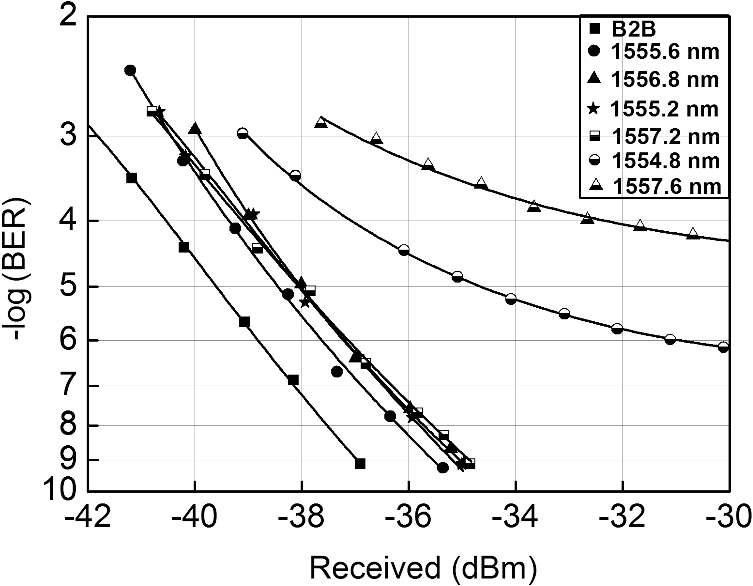
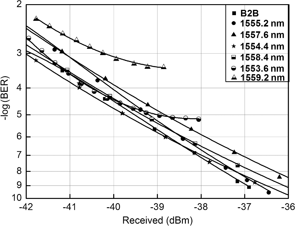
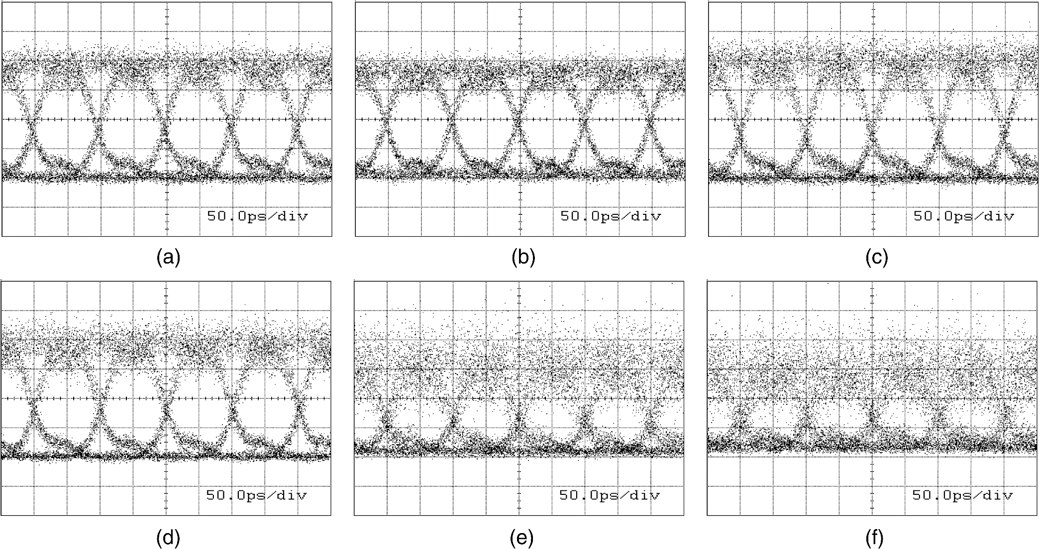
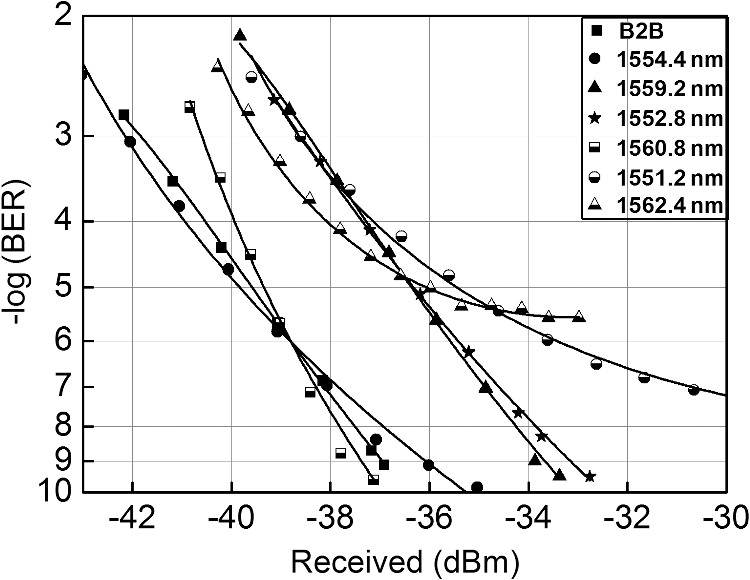
1.IntroductionSince optical fibers possess advantages such as transmission bandwidth, low transmission loss, anti-interference ability, and other characteristics, optical communication1,2 technology has gained in popularity in the communications infrastructure. Optic-electric-optic (O/E/O) conversion is a result of its development. However, this existing (O/E/O) conversion is at the expense of a complex structure, high cost, and the highest conversion efficiency is limited to an “electronic bottleneck.” Therefore, all-optical communication would be a more attractive strategy for communication modes. To be exact, the method of broadcast whose structure is simple as well as giving an advantage in terms of wavelength multiplexing tends to be more popular. 3,4 The dominant implementations of all-optical broadcast are as follows: cross-gain modulation,5–10 cross-phase modulation,11–13 and four-wave mixing (FWM) for semiconductor optical amplifier (SOA)14 and FWM for highly nonlinear fiber (HNLF).15 Since FWM has the capability of signal processing transparently in data format16 and can be used in both phase and intensity modulations, it attracts people’s interest. Furthermore, compared with FWM for SOA, FWM for HNLF has a fast response, flat broadband, and low noise. However, stimulated Brillouin scattering (SBS)17,18 limits the amount of power that can be launched into a fiber and the maximum nonlinearity that can be achieved from HNLF as well. Recently, a novel type of HNLF called aluminum-doped HNFL (AL-HNLF) has been of note for its SBS threshold, which is much higher than that of a conventional HNLF.19 With a high SBS threshold, a more efficient nonlinear process can be obtained without SBS suppression. Interestingly, the experiments using AL-HNLF do result in a high performance. The bit error rates (BERs) of most data signals reach , which indicates most signals are obtained with error-free performance. The BERs for the worst signals reach , but their performance can still be improved by error correction. In this paper, three similar experiments with channel intervals of 50, 100, and 200 GHz are conducted based on AL-HNLF and the results demonstrate a good performance of the broadcast technology based on AL-HNLF. Thus, it turns out to be adjustable and flexible for this technology in practical applications. 2.Principle of BroadcastA return-to-zero signal (at the frequency of ) with a pump light (at the frequency of ) is injected into the HNLF. As a result of the nonlinear effect in HNLF, two new signals that carry the broadcast information are generated and their frequencies are and , respectively. The frequency relationships are given by When the power of the two new signals is high enough to be a pump, another two new signals are produced at the frequencies of Similarly, as long as the new signals meet the phase match condition and have enough power, higher-order signals will be generated. In other words, the information is copied in different wavelengths. Let denote the velocity of the light in a vacuum. The FWM process in terms of wavelength could be derived by substituting into Eqs. (1)–(4). Let us take Eq. (1) for example. The corresponding wavelength relationship is given by In our experiment, the slight wavelength differences among , , result in the approximate equation . Hence, Eq. (6) becomes The relationship in Eq. (7) works for Eqs. (2)–(4) and also works for the higher-order signals that are generated in the FWM process. In our experiments, we apply the approximate equations into the whole data analysis. As shown in Fig. 1, the system components are the laser diode (LD), polarization controller (PC), intensity modulator (IM), erbium-doped fiber amplifier (EDFA), optical band-pass filter (OBF), 3-dB optical coupler (OC), AL-HNLF [length: 130 m, nonlinear coefficient: , SBS threshold for 130 m: 1000 mW, attenuation: , dispersion slope: , effective area: ], tunable band-pass filter (TBF), oscilloscope (OSC), optical spectrum analyzer (OSA), and BER tester. LD1 generates a continuous wave (CW) at a wavelength of 1556 nm (), modulated by a pseudorandom bit sequence () electrical data signal. LD2 produces another CW (at the wavelength of ); for any CW, no additional SBS suppression stages are used in this system. We adjust the PC if necessary before they are coupled into the OC. At the input of EDFA, the average power is 1.1 dBm, and the coupled signal is amplified up to 34 dBm after the EDFA. Then the amplified signal passes through the 3-nm OBF to block amplified spontaneous emission noise, and is finally launched into AL-HNLF with an average input power of 33 dBm. Different wavelengths are filtered through the TBF, which are evaluated in the OSA. The corresponding eye diagrams are shown in the OSC. Meanwhile, a BER tester is applied to analyze the performances of broadcast signals. 3.ResultsThe performances for the configurations of a 50-GHz channel interval and 1556.4-nm wavelength of generated by LD2 are described as follows. Figure 2 depicts the optical spectra at the input and output of the AL-HNLF. As shown in Fig. 2(b), six new signals are detected. The wavelengths are 1555.6, 1556.8, 1555.2, 1557.2, 1554.8, and 1557.6 nm, which are identical to the analysis above. Note that due to the device limit, before being fed into the AL-HNLF, the undesired frequency component could not be completely filtered out. Hence, as shown in Fig. 2(a), two remaining frequency components are found at and , which are caused by the nonlinear process in the EDFA. Fig. 2Optical spectra at the (a) input and (b) output of the AL-HNLF with a channel interval of 50 GHz.  Figures 3 and 4 show the optical spectra and eye diagrams at different wavelengths of the new generated signals. With a decrease of power density from to , the performance of the broadcast signals are deteriorated, especially at (1554.8 nm) and (1557.6 nm). Furthermore, the “0” level performs better than the “1” level. In brief, the clear eye diagrams from to demonstrate a good performance for the broadcast signals. Fig. 3Optical spectra of the broadcast signals after the filtering subsystem (channel space: 50 GHz).  Fig. 4Eye diagrams broadcast at different wavelengths with channel interval of 50 GHz: (a) at 1555.6 nm (), (b) at 1556.8 nm (), (c) at 1555.2 nm (), (d) at 1557.2 nm (), (e) 1554.8 nm (), and (f) 1557.6 nm ().  The BERs of broadcast signals are shown in Fig. 5. Broadcast signals at (1555.6 nm), (1556.8 nm), (1555.2 nm), and (1557.2 nm) run error free with low power, while data signals at (1554.8 nm) and (1557.6 nm) require a relatively high power to offer an error-free () approximation. However, an error floor () exists for (1554.8 nm) and (1557.6 nm), which indicates that the performance of (1554.8 nm) and (1557.6 nm) could be improved with an error-correcting code stage. The performances for the configurations of 100-GHz channel interval and 1556.8-nm wavelength of generated by LD2 are described as follows. Figure 6 represents the optical spectra at the input and output of the AL-HNLF. As shown in Fig. 6(b), six new signals are detected and their wavelengths are 1553.6, 1554.4, 1555.2, 1557.6, 1558.4, and 1559.2 nm. Figures 7 and 8 show the optical spectra and eye diagrams at different wavelengths for the new generated signals. The analysis is similar to 50 GHz. The BERs of the broadcast signals are shown in Fig. 9. The case is similar to 50 GHz. Fig. 6Optical spectra at the (a) input and (b) output of the AL-HNLF with a channel interval of 100 GHz. 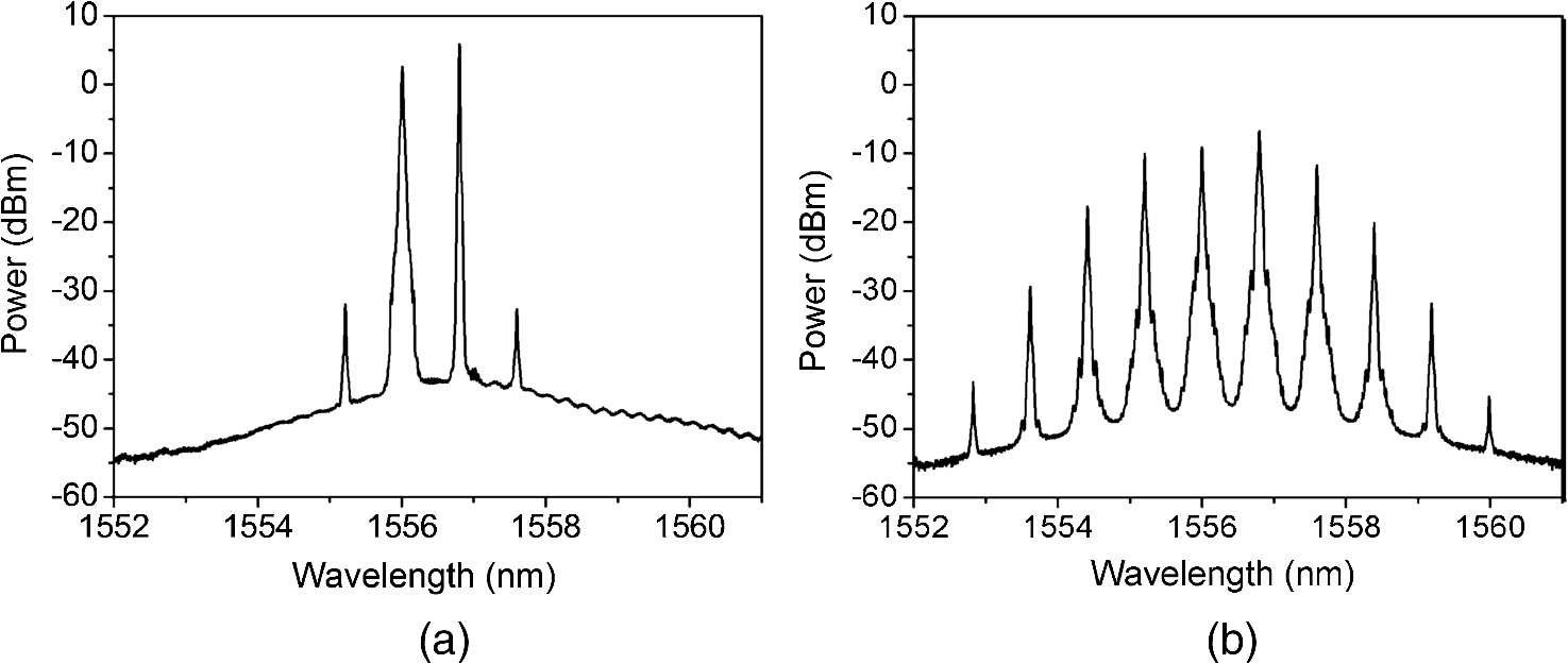 Fig. 7Optical spectra of the broadcast signals after the filtering subsystem (channel space: 100 GHz). 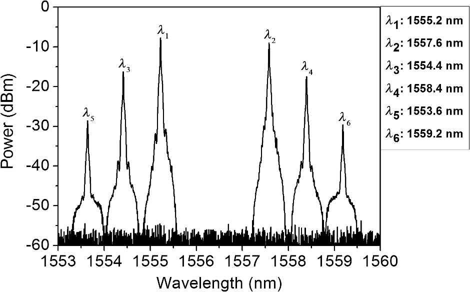 Fig. 8Eye diagrams of a broadcast at different wavelengths with channel interval of 100 GHz: (a) at 1555.2 nm (), (b) 1557.6 nm (), (c) 1554.4 nm (), (d) 1558.4 nm (), (e) 1553.6 nm (), and (f) 1559.2 nm (). 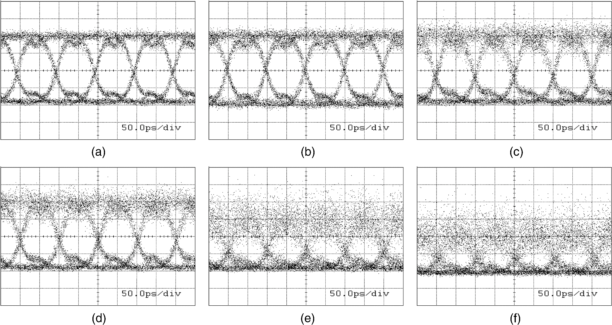 The performances for the configurations of a 200-GHz channel interval and 1557.6-nm wavelength of generated by LD2 are described as follows. Figure 10 describes the optical spectra at the input and output of the AL-HNLF. As shown in Fig. 10(b), six new signals are detected and the wavelengths are 1554.4, 1559.2, 1552.8, 1560.8, 1551.2, and 1562.4 nm. Figures 11 and 12 depict the optical spectra and eye diagrams at different wavelengths for the new generated signals. The analysis is similar to 50 GHz. The BERs of broadcast signals are shown in Fig. 13. The case is similar to 50 GHz. Fig. 10Optical spectra at the (a) input and (b) output of the AL-HNLF with a channel interval of 200 GHz. 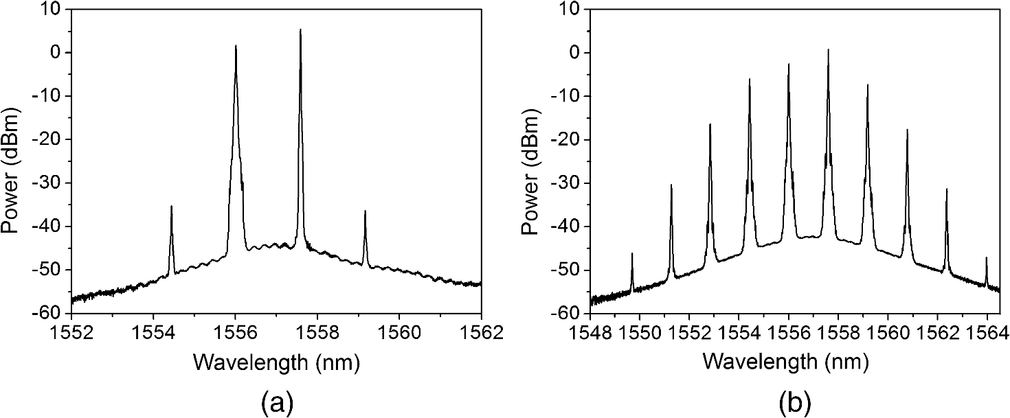 Fig. 11Optical spectra of the broadcast signals after the filtering subsystem (channel space: 200 GHz). 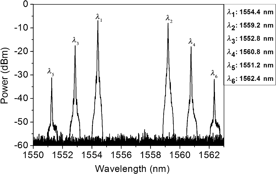 4.ConclusionIn this paper, three different channel intervals of 50, 100, and 200 GHz broadcast experiments have been implemented, respectively. The clear eye diagrams as well as the low error performance demonstrate the broadcast technology based on AL-HNLF without any SBS suppression stage. Although data signals at and are not as good as the others, they can still be improved by reducing coupling losses and losses in the AL-HNLF or increasing the magnification of the EDFA. Additionally, though these experiments are conducted at and since FWM possesses the transparent characteristics of fast response and signal processing in data format, similar results can be extracted at other rates. Consequently, these three experiments show that the wavelength is tunable, which indicates a strong application for broadcast technology. AcknowledgmentsThe authors would like to thank Professor Enze Yang and Professor Jinlong Yu at the School of Electrical and Information Engineering in Tianjin University and thank Ju Wang for the support in the experiments. ReferencesQ. HuangW.-D. Zhong,
“Wavelength-routed optical multicast packet switch with improved performance,”
J. Lightwave Technol., 27
(24), 5657
–5664
(2009). http://dx.doi.org/10.1109/JLT.2009.2033452 JLTEDG 0733-8724 Google Scholar
Q. HuangW.-D. Zhong,
“An optical wavelength-routed multicast packet switch based on multitimeslot multiwavelength conversion,”
IEEE Photonics Technol. Lett., 20
(18), 1518
–1520
(2008). http://dx.doi.org/10.1109/LPT.2008.928828 IPTLEL 1041-1135 Google Scholar
M. Ahlawatet al.,
“Tunable single-to-dual channel wavelength conversion in an ultra-wideband SC-PPLN,”
Opt. Express, 21
(23), 28809
–28816
(2013). http://dx.doi.org/10.1364/OE.21.028809 OPEXFF 1094-4087 Google Scholar
L. Liuet al.,
“Experimental demonstration of RSOA-based WDM PON with PPM-encoded downstream signals,”
Chin. Opt. Lett., 10 070608
(2012). http://dx.doi.org/10.3788/COL COLHBT 1671-7694 Google Scholar
C. L. WuS. P. SuG. R. Lin,
“All-optical data inverter based on free-carrier absorption induced cross-gain modulation in Si quantum dot doped SiOx waveguide,”
IEEE J. Sel. Top. Quantum Electron., 20
(4), 8200909
(2014). IJSQEN 1077-260X Google Scholar
X. JinT. KeatingS. L. Chuang,
“Theory and experiment of high-speed cross-gain modulation in semiconductor lasers,”
IEEE J. Quantum Electron., 36
(12), 1485
–1493
(2000). http://dx.doi.org/10.1109/3.892570 IEJQA7 0018-9197 Google Scholar
G. Contestabileet al.,
“Cross-gain modulation in quantum-dot SOA at 1550 nm,”
IEEE J. Quantum Electron., 46
(12), 1696
–1703
(2010). http://dx.doi.org/10.1109/JQE.2010.2060714 IEJQA7 0018-9197 Google Scholar
C. Meueret al.,
“Cross-gain modulation and four-wave mixing for wavelength conversion in undoped and p-doped 1.3-μm quantum dot semiconductor optical amplifier,”
IEEE J. Photonics, 2
(2), 141
–151
(2010). http://dx.doi.org/10.1109/JPHOT.2010.2044568 1943-0655 Google Scholar
M. Usamiet al.,
“Experimental analysis of cross gain modulation and cross phase modulation in SOA with assist light injection,”
in All-Optical Networking: Existing and Emerging Architecture and Applications/Dynamic Enablers of Next-Generation Optical Communications Systems/Fast Optical Processing in Optical Transmission/VCSEL,
TuK1-21
–TuK1–22
(2002). Google Scholar
A. Kapsaliset al.,
“Tunable wavelength conversion using cross-gain modulation in a vertically coupled microring laser,”
IEEE Photonics Technol. Lett., 21
(21), 1618
–1620
(2009). http://dx.doi.org/10.1109/LPT.2009.2030964 IPTLEL 1041-1135 Google Scholar
D. MarcuseA. R. ChraplyvyR. W. Tkach,
“Dependence of cross-phase modulation on channel number in fiber WDM systems,”
J. Lightwave Technol., 12
(5), 885
–890
(1994). http://dx.doi.org/10.1109/50.293982 JLTEDG 0733-8724 Google Scholar
J. Y. Yanget al.,
“All-optical chromatic dispersion monitoring for phase-modulated signals utilizing cross-phase modulation in a highly nonlinear fiber,”
IEEE Photonics Technol. Lett., 20
(19), 1642
–1644
(2008). http://dx.doi.org/10.1109/LPT.2008.2002740 IPTLEL 1041-1135 Google Scholar
A. Matsumotoet al.,
“Operational design on high-speed semiconductor optical amplifier with assist light for application to wavelength converters using cross-phase modulation,”
IEEE J. Quantum Electron., 42
(3), 313
–323
(2006). http://dx.doi.org/10.1109/JQE.2006.869809 IEJQA7 0018-9197 Google Scholar
G. ContestabileM. PresiE. Ciaramella,
“Multiple wavelength conversion for WDM multicasting by FWM in an SOA,”
IEEE Photonics Technol. Lett., 16 1775
(2004). http://dx.doi.org/10.1109/LPT.2004.828349 IPTLEL 1041-1135 Google Scholar
Q. HaoH. Zeng,
“Cascaded four-wave mixing in nonlinear Yb-doped fiber amplifiers,”
IEEE J. Sel. Top. Quantum Electron., 20
(5), 1
–5
(2014). http://dx.doi.org/10.1109/JSTQE.2014.2354634 IJSQEN 1077-260X Google Scholar
D. F. Geraghtyet al.,
“Wavelength conversion for WDM communication systems using four-wave mixing in semiconductor optical amplifiers,”
IEEE J. Sel. Top. Quantum Electron., 3
(5), 1146
–1155
(1997). http://dx.doi.org/10.1109/2944.658588 IJSQEN 1077-260X Google Scholar
R. Suet al.,
“Proposal of interaction length for stimulated Brillouin scattering threshold of nanosecond laser in optical fiber,”
Opt. Laser Technol., 57 1
–4
(2014). http://dx.doi.org/10.1016/j.optlastec.2013.09.031 OLTCAS 0030-3992 Google Scholar
R. Suet al.,
“Numerical analysis on impact of temporal characteristics on stimulated Brillouin scattering threshold for nanosecond laser in an optical fiber,”
Opt. Commun., 316 86
–90
(2014). http://dx.doi.org/10.1016/j.optcom.2013.10.073 OPCOB8 0030-4018 Google Scholar
T. Nakanishiet al.,
“ core highly nonlinear dispersion-shifted fiber with Brillouin gain suppression improved by 6.1 dB,”
in 32nd European Conf. on Optical Communication (ECOC) 2006,
(2006). Google Scholar
BiographyLijuan Li is a graduate student at Tianjin University. She received her BS degree in communication engineering from Tianjin University in 2012. Her current research interests include optical application and sensors. Jinlong Yu received his MS and PhD degrees from Tianjin University, China, in 1994 and 1997, respectively. In 1997, he joined Tianjin University. He became a full professor and group leader in the Optical Fiber Communication Laboratory of Tianjin University. He researches high-speed optical signal processing and functional elements for radio over fiber and RoF applications. Ju Wang received her BS and MS degrees from Tianjin University in 2008 and 2010, respectively, and her PhD degree from Tianjin University in 2013. Her doctoral work principally concerned optical signal processing, especially all-optical regeneration in highly nonlinear fiber. In 2012, she joined the High-Speed Optical Communications Group at the Technical University of Denmark as a visiting PhD student. Since September 2012, she has been working with the Optical Fiber Communication Laboratory of Tianjin University. Her research interests include all-optical signal processing and optoelectrical oscillators. Wenrui Wang is an associate professor at Tianjin University and his research interests include optical fiber communication and photonic microwaves. Qiong Wu is a graduate student at Tianjin University whose current research interests include optical application and sensors. |