|
|
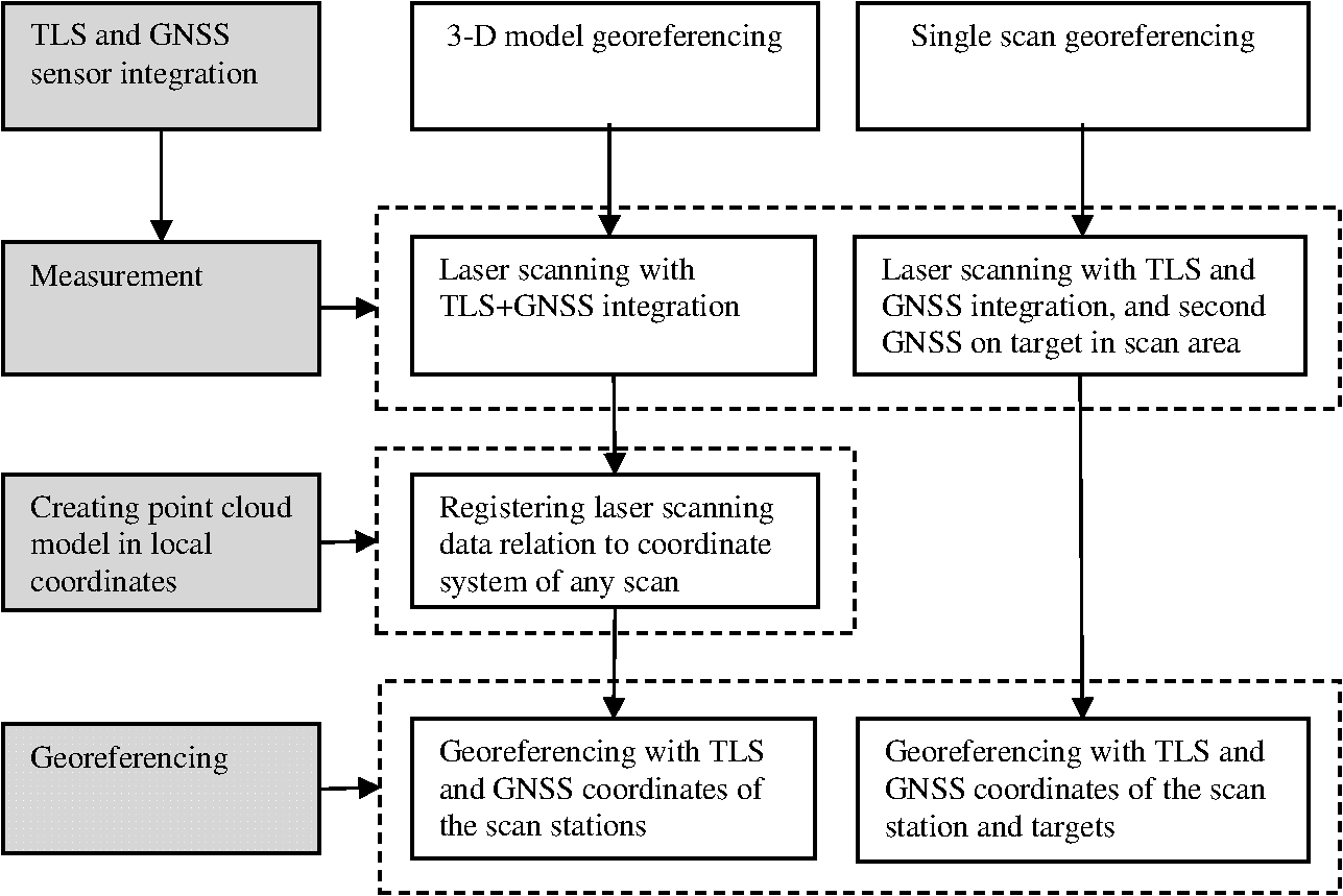
1.IntroductionThe three-dimensional (3-D) modelling of an object or surface requires high density point data (). The 3-D model that is created depicts all details of the measured surfaces as close as possible to the real shape. Thus, 3-D models of objects and surfaces are created for various purposes such as the documentation of cultural heritage, deformation measurement, medical visualization, and urban visualization in a geographic information system (GIS). A terrestrial laser scanner (TLS) can rapidly measure a study area with a certain point separation (distance from point to point on the object). Many scans are performed to image all the details of an object and a 3-D point cloud model is created in local coordinate system by combining these scans. The created model should be registered (, , rotations and , , translations) into a geodetic coordinate system in order to allow association with other spatial data. Furthermore, spatial information technology and data management require the registration of all spatial data from different sources into a common coordinate system. National, international, or global coordinate systems can be used as a common coordinate system. The global navigation satellite system (GNSS) is widely used for positioning and navigation purposes based on the world geodetic system established in 1984 (WGS84). On the other hand, the international terrestrial reference frame (ITRF) is a global coordinate system for geodetic measurements. Registration between these coordinate systems is always possible. Georeferencing is the term given to the registration of local measurements to a geodetic coordinate system. The methods used to register laser scanner measurements to a geodetic coordinate system can be categorized into three groups; indirect georeferencing, direct georeferencing, and surface matching.1,2 Indirect georeferencing is conducted using control points that have coordinates on the model and geodetic system. The registration parameters (three rotations and three translations) are calculated using at least three control points. The special target placed in the measurement area or significant details that can be distinguished on the model are used as control points. In this method, the geodetic coordinates of the control points have to be measured with terrestrial methods.2–4 Marking and measuring the control points require extra time and cost. On the other hand, more than three control points should be used to achieve high accuracy in georeferencing. Direct georeferencing can be realized with various techniques. References 5 and 6 estimated the rotations between the axes of a laser scanner and geodetic system by mounting a telescope on the laser scanner. For the measurement, the laser scanner is set up on a point and rotated to the direction of another point using the telescope. For this technique, the coordinates of the laser scanning station and the observed point must be known and this restricts the application of this method. Another technique for direct georeferencing is the use of GNSS or a compass with the laser scanner.1,7–9 The GNSS receiver mounted on the laser scanner can measure the coordinates of the laser scanning station in the WGS84 datum. The rotation of the scanner is determined by the GNSS placed within the scanning area or by a compass mounted on the scanner. However, the configuration of the laser scanner, GNSS, and compass reduces the accuracy of the method. In another study, laser scanning data were georeferenced by a combination of TLS and GNSS.10 Reference 6 investigated the errors and their propagation in direct georeferenced terrestrial laser scanner networks. In addition, the reasons and effects of several systematic errors inherent to TLS datasets were presented. According to the study, the laser beam width has a significant effect on the rotation accuracy of the scan data. The usage of the TLS and GNSS combination for georeferencing is explained by Ref 11, in which was presented an autonomous way for orientation of point clouds relative to the geodetic coordinate system. Using a dual-GNSS antenna apparatus on the TLS, rotation angles have been determined with a precision of about 0.05 deg. Georeferencing with surface matching is the registration of point clouds to the previous georeferenced point cloud dataset. Surface matching is applied with the iterative closest point (ICP),12–14 least-square 3-D surface matching,15 or other methods.16 This paper proposes a 3-D model georeferencing and single scan georeferencing methods. Initially, the TLS and the GNSS receiver were integrated. Then the registration of the point cloud to the geodetic coordinate system was performed by the GNSS data from the continuously operating reference stations-turkey (CORS-TR) network. In the next part of the paper, Sec. 2 describes the GNSS, laser scanning, and the proposed measurement methods. The integration of the TLS and GNSS and georeferencing results are given in Sec. 3, and the discussion and conclusions are presented in Secs. 4 and 5, respectively. 2.Materials and Methods2.1.Terrestrial Laser ScanningA laser scanner measures the coordinates () and reflectance (intensity) of each scan point at very high speed. In addition, color values are recorded for the points from the images of the camera integrated to the scanner. The measurements have their own local coordinates, the center of which is the device in each station. One of the scans is usually selected as a reference and all the others are registered to its coordinate system. Therefore, a 3-D point cloud model of the measured object is generated in the local coordinate system. The laser scanner data,15,17–19 camera image,20,21 or a combination of both22 can be used in the registration of point clouds. ICP is the most widely used method in practice.12–14 In the execution of this method, after applying coarse registration, closest point pairs are determined between the reference and moving point clouds and fine registration is iteratively applied with these closest points. In this study, the Ilris 3-D terrestrial laser scanner was used to perform the measurements. This device uses a time-of-flight technique to measure the distance from the laser scanner to the object points. It has a maximum measurement distance of 1300 m, measurement accuracy of 7 mm at 100 m, and the measurement speed is 2500 points per second.23 2.2.Global Navigation Satellite SystemThe global positioning system (GPS) is a radio navigation system which was developed by the United States Department of Defense in 1974 for navigation purposes. GPS is a four-dimensional system; 3-D Cartesian coordinates () and the time (T) of the receiver are measured (3-D + T).24 The system enables momentary and constant identification of position, speed, and time at any place, in all weather conditions, on a global coordinate system, at high precision and in an economic manner.25 A short time later, the system was made available for civil users and applied to geodetic problems. It is used in various fields such as measurement, densification of state geodetic networks, detail measurement, and location application. It is also used for data location measurement for GIS, transportation, energy, agriculture, and tourism. GPS has made significant contributions to studies in terms of time, speed, and cost. After the original GPS system was developed by the inclusion of Galileo (Europe) and Glonass (Russia) satellites into the GPS satellite system, it was called GNSS. The positioning methods using GNSS can be categorized as absolute and relative. In absolute positioning, the coordinates of the point on which the receiver is set up are determined. The method is based on the principle of space resection using a satellite-receiver distance and multiplying by the time elapsed. On the other hand, in relative positioning, the coordinates of one or more points are determined according to a point with known coordinates. In other words, the base vector between two points is determined in relative positioning.25 Simultaneous code or phase observations are conducted with the same satellites using two receivers set up at two different points for relative positioning. Relative positioning achieves a much better accuracy than absolute positioning; it varies between 0.001 and 100 ppm depending on the receiver type (P coded, P codeless), measurement time, observed satellite geometry, number of satellites, and ephemeris information (broadcast or sensitive) that is used.25 Relative positioning conducted using phase observations is applied in static and kinematic modes. The measurement methods can be categorized as static, fast static, iterative, stop-and-go, and kinematic according to the base length, measurement time, and evaluation method.24,25 The CORS networks consist of stationary GNSS receiver stations with a certain range on a country or regional scale. The CORS stations record the GNSS signals from the satellites and share them with civil users. Using the CORS station measurements, reference ellipsoid coordinates within the CORS network can be measured by relative or absolute positioning using a single GNSS receiver. CORS-TR consists of 146 GNSS receiver stations which have ITRF coordinates across the country.26,27 By this means, the measurement based on ITRF can be undertaken with a single GNSS receiver at any place and time on the CORS area. The users can receive GNSS data from CORS-TR by a mobile phone modem for absolute positioning or from the Internet for postprocessing of the measurement data. In this study, the positions of the GNSS stations were measured using the relative positioning method. The measurement was realized using a Topcon Hiper Plus double frequency geodetic GNSS receiver. 2.3.Proposed Georeferencing MethodsIn order to apply the georeferencing methods proposed in this study, first, a GNSS receiver was mounted on the TLS and the translations between their phase centers were estimated by calibration measurement (Fig. 1). The calibration results are used in all measurements conducted using this integration of TLS and GNSS. Two methods were proposed for georeferencing (Fig. 2):
3.Results3.1.Sensor Integration of Terrestrial Laser Scanner and Global Navigation Satellite SystemThe Topcon Hiper Plus GNSS receiver was mounted on the Ilris 3-D laser scanner using a special apparatus. The origin of the laser scanner coordinate system is the phase center of the device, and the axes are as follows: view direction, , right direction, and upper direction, . The relationship between the ITRF and TLS coordinate systems is given by the 3-D Helmert similarity registration.28 where are the ITRF coordinates and are the TLS coordinates. Since the coordinates in each system are in real dimensions, the scale () between the two coordinate systems is 1. , , are the coordinates of the origin of the TLS coordinate system in the ITRF96 datum 2005.0 epoch. In this equation, at least three points with known coordinates in both systems are required to solve unknown rotations (, , ) and translations (, , ). Since the rotations between coordinate axes of TLS and ITRF will change at each position of the TLS, only the translations between their coordinate axes are estimated (Fig. 3). The translations are given by where, and are the phase center coordinates of the TLS and GNSS in relation to ITRF96 datum 2005.0 epoch, respectively. are the translations between the phase center of the TLS and GNSS receiver. In other words, these are the phase center coordinates of the GNSS receiver in relation to the coordinate system of the TLS.Fig. 3TLS and ITRF coordinate systems and the position of GNSS receiver on the TLS and on the target sign. 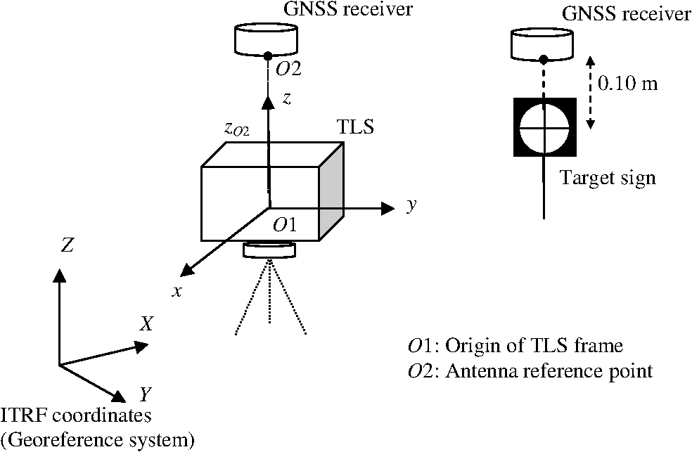 The TLS and GNSS integration was set up a random place and levelled to a horizontal plane. Another GNSS receiver placed on target shape was measured by the TLS (Fig. 3). The combination of GNSS and target sign was pointed at different locations in the measurement area keeping the position of the integrated TLS and GNSS. Laser scanning was undertaken with a 3-mm point separation (the distance between the measured points on the object) at 11 locations of the target. The GNSS data were recorded at each laser scanning station and every location of the target. Thus, the control points which have laser scanner and GNSS coordinates were constituted. The offset between the center of the target sign and the GNSS receiver placed on it was 10 cm on the vertical axis (Fig. 3). The standard deviations of the Cartesian coordinates measured by GNSS were 0.002, 0.001, and 0.001 m, respectively. On the other hand, the laser scanner coordinates of the control points were interactively measured from the point clouds. Here, since the axis of the coordinate systems in the integration of TLS and GNSS receiver are intersected, the translations in the direction of the and axes are zero. The translation in the direction of the axis was estimated with 11 control points by using Eqs. (1) and (2) (Table 1). Table 1Coordinates of the global navigation satellite system (GNSS) receiver mounted on a laser scanner according to the coordinate system of the laser scanner (Fig. 3).
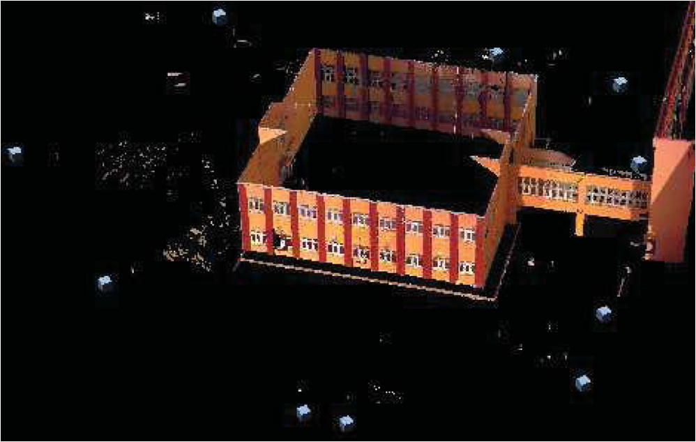
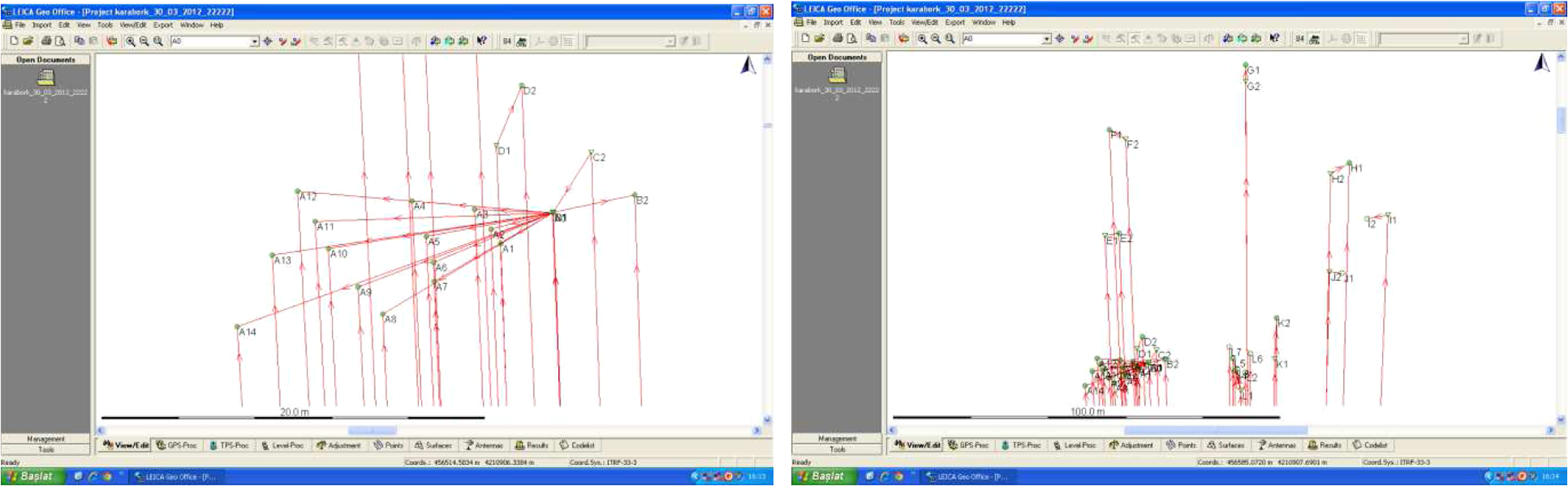
3.2.Georeferencing3.2.1.Three-dimensional model georeferencingA 3-D model of a building was created to demonstrate the application of the proposed georeferencing method. Overlapping scans were undertaken by the integration of TLS and GNSS at 10 stations with a 1-cm point separation (Fig. 4). Furthermore, check points were constituted by measuring the target joined to GNSS in the field of view. The static GNSS data were recorded for a minimum period of 7 min at each laser scanning station. The data recording period was 1 s and the satellite altitude angle was 10 deg on the measurement. To combine the laser scanning data, the first scan was selected as a reference, and then all the others were registered to the coordinate system of this scan using ICP with PolyWorks software.29 Thus, a point cloud model was generated in a local coordinate system (Fig. 5). The maximum standard deviation on registration of the point clouds was 0.009 m. The collected GNSS data were first converted into receiver independent exchange (RINEX) format. 1-sec RINEX data of the KNYA station located in the CORS-TR were supplied to evaluate the GNSS measurement (Fig. 6). Fig. 6Distribution of the fixed GNSS stations in continuously operating reference stations in the network Turkey (CORS-TR).26,30 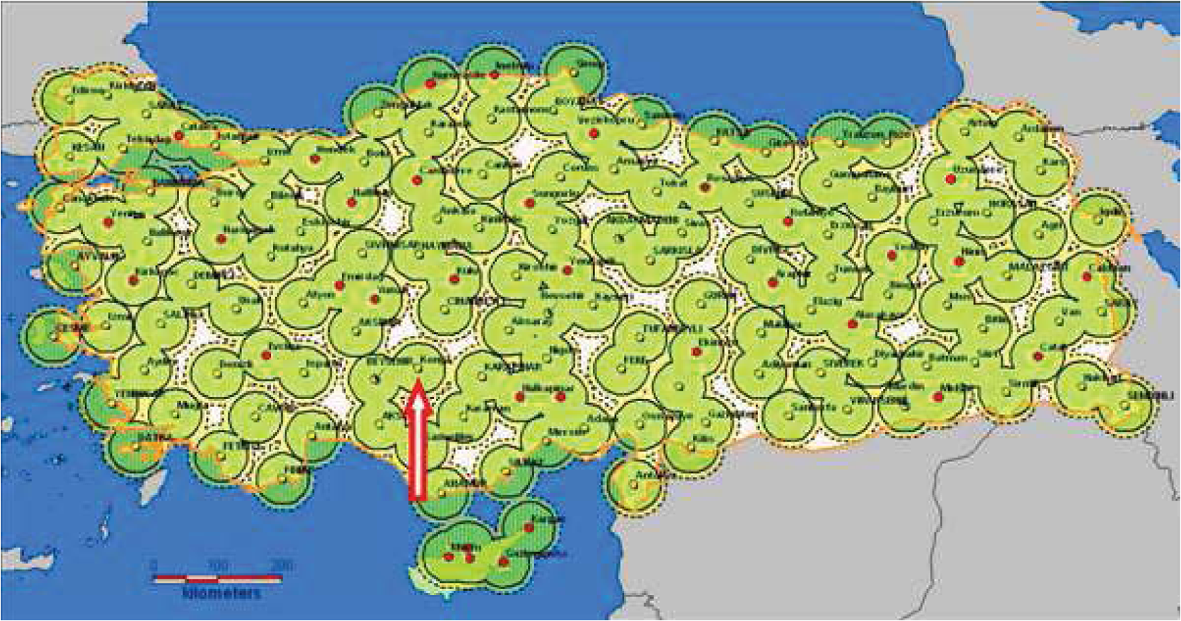 Leica Geo Office software was used to analyze the GNSS data. The ITRF coordinates of laser scanning stations were calculated taking the offset translation into consideration (it is 0.329 m in Table 1). On the processes of the measurements, the bases from the KNYA point in the CORS-TR network were analyzed by the GNSS receiver mounted on the Ilris laser scanning device and the target. Thus, each point was evaluated by triangles with two independent bases (Fig. 7). The analysis of the created triangle revealed that the largest triangle closure was 0.0168 m. The base measurements and loops also showed that there was no contrary measurement. The procedure continued with the adjustment of the network. In the adjustment, ITRF96 datum 2005.0 epoch coordinates of the KNYA point were taken as fixed; thus, the coordinates of all points were calculated in the ITRF96 datum 2005.0 epoch. The standard deviations of the computed points showed that the greatest values were in latitude; in longitude; and in altitude. These results indicate that the coordinates obtained from GNSS measurements were calculated with high accuracy. The ITRF and point cloud coordinates of the laser scanning stations must be known to register the 3-D model into the geodetic system. The laser scanning stations in the coordinate system of the reference point cloud were computed during the registration of point clouds. The coordinates of the check points were interactively extracted from the point cloud model. Then the point cloud model was georeferenced by a various number of control points (laser scanning stations). The accuracy was assessed with the residuals on the check points (Table 2). Table 2Generated three-dimensional (3-D) model georeferencing using a varying number of laser scanning stations (laser scanning was performed by the integration of TLS and GNSS).
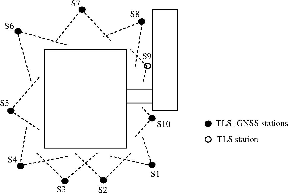
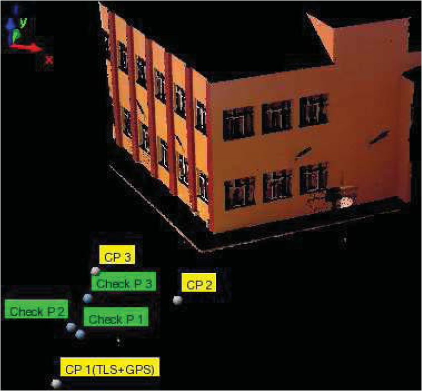
3.2.2.Single scan georeferencingThe individual georeferencing of the data of each laser scanning requires two control points in addition to the laser scanning station. To achieve this, control points were constituted on the measurement area (Fig. 8). The points, signed by the target sign, have TLS and GNSS coordinates. In addition, the check points were constituted in the same way. The registration to the ITRF coordinate system was performed using three control points. The residuals on the check points were exploited to assess the accuracy of the registration (Table 3). Table 3Results of the single scan georeferencing.
4.DiscussionsThe offset ( coordinate) between the phase centers of the integrated TLS and GNSS receivers was estimated using 11 control points; however, a higher number of control points and different techniques can be used. Sufficient accuracy was obtained in the georeferencing of the measurement by this sensor combination. After the point cloud model was created in the local coordinate system, the model coordinates were registered to the georeference system with the 3-D model georeferencing method. The laser scanning stations (TLS+GNSS) were taken as the control points which have coordinates in both systems (ITRF and TLS). However, the GNSS signal might not be received at each station due to obstacles in the route of the satellite signals. In the experiment, the satellite signal was not received from a sufficient number of satellites at station 9. Therefore, the ITRF coordinates of this station could not be computed. The georeferencing was performed by varying the number of control points (laser scanning stations). This proved that the residuals on the check points were very small even though three control points were used (Table 2). A reason for the difference in the accuracy of georeferencing is the device drift from the horizontal plane during the laser scanning at each station. It causes a change in the direction of the axis of the laser scanner. Therefore, the offset () between the origins of TLS and GNSS changes a little. In addition, small changes occur on and . Although these effects decrease the accuracy of the georeferencing, this is an insignificant effect due to the small drift. In the single scan georeferencing method, each laser scanning measurement performed by the integration of TLS and GNSS was registered to the geodetic coordinate system using two control points constituted in the scan area. Thus, both combination and georeferencing are undertaken in one step. The residuals on the check points indicated that the method has high accuracy (Table 3). In this study, the single scan georeferencing and 3-D model georeferencing methods have high accuracy. The single scan georeferencing method requires two control points in the scan field; thus, it needs more computation and is labor intensive. However, the 3-D model georeferencing method does not require a second GNSS receiver and a point that has ITRF coordinates. After the 3-D model is generated by the integration of TLS and the GNSS receiver in relation to the local coordinate system, it is georeferenced with the laser scanning stations without any control points. It needs scanning from three or more stations. 5.ConclusionsGeoreferencing of laser scanning data is the integration of point clouds with the other spatial data in a geodetic coordinate system. It is essential in areas of planning and visualization and for responding to spatial queries. This study presented the registration of laser scanner measurements to the geodetic coordinate system using the integration of TLS and GNSS in the CORS-TR network. The laser scanner measurements were registered to the ITRF datum with the CORS-TR station closest to the laser scanning field. The present study adopted a 3-D model georeferencing and single scan georeferencing methods. The 3-D model georeferencing method has multi scan overlapping. After the 3-D model is generated, the relation to the local coordinate system of the scan is selected as a reference, the georeferencing is performed by GNSS data of the scanning stations. However, the single scan georeferencing method requires a second GNSS receiver to create the control points. Consequently, the current study found that the proposed georefrencing methods were suitable for outdoor work and were more practical. ReferencesS. SchuhmacherJ. Böhm,
“Georeferencing of terrestrial laser scanner data for applications in architectural modelling,”
in Proc. ISPRS 3D-ARCH 2005: Virtual Reconstruction and Visualization of Complex Architectures, Int. Arch. Photogramm. Remote Sens. Spatial Inf. Sci.,
7
(2005). Google Scholar
M. AlbaM. Scaioni,
“Comparison of techniques for terrestrial laser scanning data georeferencing applied to 3-D modelling of cultural heritage,”
in Proc. ISPRS 3D-ARCH 2007: Virtual Reconstruction and Visualization of Complex Architectures, Int. Arch. Photogramm. Remote Sens. Spatial Inf. Sci.,
8
(2007). Google Scholar
M. ScaioniG. Forlani,
“Independent model triangulation of terrestrial laser scanner data,”
in Proc. ISPRS WG V/4 Workshop, Int Arch. Photogramm. Remote Sens. Spatial Inf. Sci.,
308
–313
(2003). Google Scholar
I. ElkhrachyW. Neimeier,
“Optimization and strength aspects for geo-referencing data with terrestrial laser scanner systems,”
in Proc. 3rd IAG/12th FIG Symp.,
10
(2006). Google Scholar
M. Scaioni,
“Direct georeferencing of TLS in surveying of complex sites,”
in Proc. ISPRS 3D-ARCH 2005: Virtual Reconstruction and Visualization of Complex Architectures, Int. Arch. Photogramm. Remote Sens. Spatial Inf. Sci.,
8
(2005). Google Scholar
D. D. LichtiS. J. GordonT. Tipdecho,
“Error models and propagation in directly georeferenced terrestrial laser scanner networks,”
J. Surv. Eng., 131
(4), 135
–142
(2005). http://dx.doi.org/10.1061/(ASCE)0733-9453(2005)131:4(135) JSUED2 0733-9453 Google Scholar
M. Balzaniet al.,
“CyraxTM 2500 laser scanner and GPS operational flexibility: from detailed close range surveying to urban scale surveying,”
in Proc. CIPA WG 6 Int. WS Scanning Cultural Heritage Rec.,
27
–32
(2002). Google Scholar
J. BöhmN. HaalaY. Alshawabkeh,
“Automation in laser scanning for cultural heritage applications,”
Recording, Modeling and Visualization of Cultural Heritage, 443
–450 Taylor & Franzis Group, London, UK
(2006). Google Scholar
J. A. Paffenholz,
“Direct geo-referencing of 3D point clouds with 3D positioning sensors,”
Deutsche Geodatische Kommission bei der Bayerischen Akademie der Wissenschaften,
(2012). Google Scholar
M. J. Olsenet al.,
“Terrestrial laser scanning of extended cliff sections in dynamic environments: parameter analysis,”
J. Surv. Eng., 135
(4), 161
–169
(2009). http://dx.doi.org/10.1061/(ASCE)0733-9453(2009)135:4(161) JSUED2 0733-9453 Google Scholar
B. E. Wilkinsonet al.,
“A novel approach to terrestrial LIDAR georeferencing,”
Photogramm. Eng. Remote Sens., 76
(6), 683
–690
(2010). http://dx.doi.org/10.14358/PERS.76.6.683 PERSDV 0099-1112 Google Scholar
P. J. BeslN. D. McKay,
“A method for registration of 3-D shapes,”
IEEE Trans. Pattern Anal. Mach. Intel., 14
(2), 239
–256
(1992). http://dx.doi.org/10.1109/34.121791 ITPIDJ 0162-8828 Google Scholar
Y. ChenG. Medioni,
“Object modelling by registration of multiple range images,”
Image Vis. Comput., 10
(3), 145
–155
(1992). http://dx.doi.org/10.1016/0262-8856(92)90066-C IVCODK 0262-8856 Google Scholar
Z. Zhang,
“Iterative point matching for registration of free-form curves and surfaces,”
Int J. Comput. Vis., 13
(2), 119
–152
(1994). http://dx.doi.org/10.1007/BF01427149 IJCVEQ 0920-5691 Google Scholar
A. GruenD. Akca,
“Least squares 3-D surface and curve matching,”
ISPRS J. Photogramm. Remote Sens., 59
(3), 151
–174
(2005). http://dx.doi.org/10.1016/j.isprsjprs.2005.02.006 IRSEE9 0924-2716 Google Scholar
A. Nüchteret al.,
“Study of parameterizations for the rigid body transformations of the scan registration problem,”
Comput. Vis. Image Und., 114
(8), 963
–980
(2010). http://dx.doi.org/10.1016/j.cviu.2010.03.007 CVIUF4 1077-3142 Google Scholar
D. Zhanget al.,
“Robust algorithm for registration of building point clouds using planar patches,”
J. Surv. Eng., 138
(1), 31
–36
(2012). http://dx.doi.org/10.1061/(ASCE)SU.1943-5428.0000063 JSUED2 0733-9453 Google Scholar
J. Y. HanN. H. PerngY. T. Lin,
“Feature conjugation for intensity-coded LIDAR point clouds,”
J. Surv. Eng., 139
(3), 135
–142
(2013). http://dx.doi.org/10.1061/(ASCE)SU.1943-5428.0000106 JSUED2 0733-9453 Google Scholar
C. Altuntas,
“Pair-wise automatic registration of three-dimensional laser scanning data from historical building by created two-dimensional images,”
Opt. Eng., 53
(5), 053108
(2014). http://dx.doi.org/10.1117/1.OE.53.5.053108 OPEGAR 0091-3286 Google Scholar
K. Al-ManasirC. S. Fraser,
“Registration of terrestrial laser scanner data using imagery,”
Photog. Rec., 21
(115), 255
–268
(2006). http://dx.doi.org/10.1111/(ISSN)1477-9730 PGREAY 0031-868X Google Scholar
S. BarneaS. Filin,
“Registration of terrestrial laser scans via image based features,”
in Proc. ISPRS Workshop on Laser Scanning 2007 and SilviLaser 2007, Int. Arch. Photogramm. Remote Sens. Spatial Inf. Sci.,
32
–37
(2007). Google Scholar
D. G. AquileraP. R. GonzalvezJ. G. Lahoz,
“An automatic procedure for co-registration of terrestrial laser scanners and digital cameras,”
ISPRS J. Photogramm. Remote Sens., 64
(3), 308
–316
(2009). http://dx.doi.org/10.1016/j.isprsjprs.2008.10.002 IRSEE9 0924-2716 Google Scholar
Optech, “Ilris-3D specifications,”
(2006) http://archive.cyark.org/temp/Optechilris36d.pdf Google Scholar
P. H. Dana,
“The global positioning system,”
The Geographer’s Craft Project,
(2014) http://www.colorado.edu/geography/gcraft/notes/gps/gps_f.html May ). 2014). Google Scholar
M. KahveciF. Yıldız, Global konum belirleme sistemi teori-uygulama, Baskı, Nobel Yayın Dağıtım, Ankara (2005). Google Scholar
K. Erenet al.,
“Results from a comprehensive global navigation satellite system test in the CORS-TR network: case study,”
J. Surv. Eng., 135
(1), 10
–18
(2009). http://dx.doi.org/10.1061/(ASCE)0733-9453(2009)135:1(10) JSUED2 0733-9453 Google Scholar
CORS-TR, “Establishment of national CORS system and determination of datum transformation parameters,”
(2014) http://cors-tr.iku.edu.tr/en_corstr_projeozetigenel.htm May ). 2014). Google Scholar
K. Kraus, Photogrammetry: Geometry from Images and Laser Scans, 2nd ed.Walter de Gruyter, Berlin, New York
(2007). Google Scholar
(2005). Google Scholar
O. Yildirimet al.,
“TUSAGA-AKTİF (CORS TR) projesi ve ülkemize katkıları,”
in Ulusal Coğrafi Bilgi Sistemleri Kongresi,
7
(2007). Google Scholar
BiographyCihan Altuntas has been a lecturer at Selcuk University. He received his BS, MS, and PhD degrees in geomatics from Selcuk University in 1998, 2002, and 2011, respectively. He was a visiting researcher at the University of Vienna and the University of Calgary in 2009 and 2013, respectively. He has been an author and a reviewer in many qualified journals. His research interests include photogrammetry, LIDAR applications, three-dimensional (3-D) modeling, range imaging camera, and sensor combination. Hakan Karabork received his BS and MS degrees in geomatics engineering from Selcuk University, Turkey, in 1991 and 1996, respectively. He received his PhD degree in geomatics engineering from Selcuk University in 2002. He has been an associate professor in the Division of Geomatics at Selcuk University since 2010. His research interests include photogrammetry and image processing. Ekrem Tusat received his BS and MS degrees in geomatics engineering from Selcuk University, Turkey. He received his PhD degree in geomatics engineering from Selcuk University. He has been an associate professor in Cumra Vocational School at Selcuk University since 2013. His research interests include geodesy and GNSS computations. |
|||||||||||||||||||||||||||||||||||||||||||||||||||||||||||||||||||||||||||||||||||||||||||||||