|
|
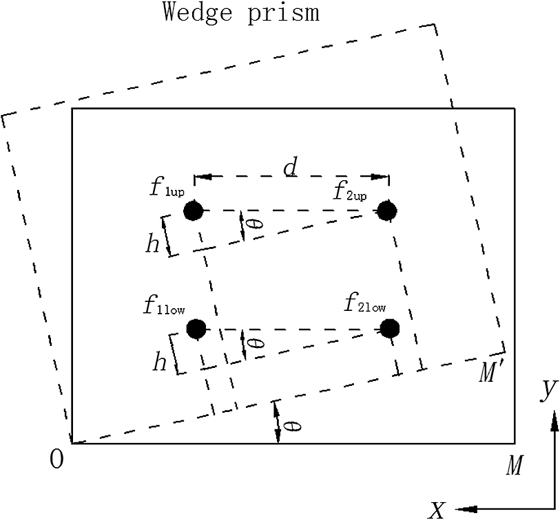
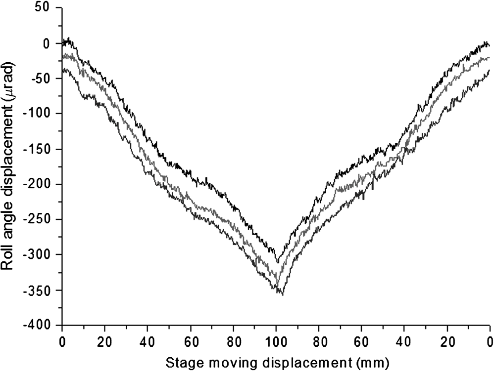
1.IntroductionAs a development resulting from high-tech fields such as the military industry, aerospace engineering, and digital controlled machine tools, the precision benchmark metrology and the precision measurement for geometrical quantities become more and more important. As a key part in such machines, a moving table along a specified axis has six-degree of freedom errors, among which the roll-angle error has received more and more attention for lack of a suitable measuring method. Currently, many methods have been developed to measure the roll error.1–14 One of the most researched methods is based on optical heterodyne phase detection with a wave plate and polarizer. This method has been improved to achieve a higher sensitivity by using a quarter-wave plate to produce elliptically polarized light and a polarizer or a half-wave plate adopted as a sensor.1–4 This method has the advantages of simple structure and full period measurement; moreover, it was used for measuring the roll angle of guided missiles and other aircraft.5,6 Another technique based on propagation of polarized light is highly sensitive in a relatively large measurement range.7–9 This kind of sensor is often composed of a polarized light source whose polarization is modulated by an ac signal, an analyzer, and an optical detector. But it is difficult to achieve a resolution better than 0.01 deg. The traditional method of interferometer measurement for roll angle is using a plane in the same length as that of the travel path and is typically mounted on and moving with the moving body to be measured, where the incident beam from the source is reflected by this mirror and then detected by a photoelectric detector.10 Methods like this can achieve high resolution, but suffer from various disturbances. Baldwin11 has disclosed an interferometer for measuring straightness and roll which is, however, limited in application due to the requirement of two expensive Wollaston prisms and the difficult orientation of the target mirror to the Wollaston prism. Hou et al.13,14 have designed a roll-angle measurement system based on a differential plane mirror interferometer that has good stability and a measurement resolution of submicroradians. Two sets of centrosymmetric beams are used to travel through the measurement and the reference arms of roll-angle interferometer, which contains two specific optical devices: a wedge prism assembly and a wedge mirror assembly. Changes of the optical path in the interferometric arms by roll are differential and converted into a phase shift through a particular interferometer system. In the system, the wedge prism assembly and the wedge mirror assembly, both composed of two asymmetrical parts, are used as core components which, to some extent, increase the difficulty in applications. Based on the research in Refs 13 and 14, we present an enhanced roll-angle measurement system which only uses one wedge prism and one wedge mirror as the core components. To a certain extent, this roll-angle measurement system used fewer optical components, which increases the stability of the measurement and is more convenient for adjusting. In the system, two parallel beams which have slightly different frequencies travel through a wedge prism and backtrack by the wedge mirror. The line of the two incidence points on the wedge mirror is perpendicular to the direction of the wedge angle. With the help of a Koster prism, a corner cube, and a quarter-wave plate, the two beams with different frequencies make a round trip through the wedge prism two times, which doubled the measurement resolution of the roll angle. 2.Optical Structure of Roll-Angle Measurement InterferometerThe optical schematic of the new system is shown in Fig. 1. The optical structure of the roll-angle measurement system comprises a Koster prism, a quarter-wave plate, a corner cube, a wedge prism, and a wedge mirror. The wedge angles of the prism and mirror are and , respectively. Here, the wedge prism is employed as the roll-angle sensor and is mounted on the travel stage, while the wedge mirror is fixed in position. The incoming laser beam is comprised of two orthogonally polarized beams, a horizontally polarized beam and a vertically polarized beam , which come from a dual-frequency stabilized laser source that could be a transverse Zeeman-effect laser, longitudinal-mode laser, or acousto-optic modulator laser, and so on. The Koster prism separates the two partial beams into two parallel beams with a distance of . Both beams pass through the quarter-wave plate and change the polarization states into circularly polarized, but still orthogonal to each other. The two beams travel through the wedge prism, backtrack by the wedge mirror and pass through the quarter-wave plate for the second time, and then the two circularly polarized beams change polarizations and become two linear orthogonally polarized beams, and . They are recombined in the Koster prism and go out as beam to the corner cube. The beam is reflected by the corner cube and returned back into the Koster prism. The Koster prism splits the two partial beams again into two parallel beams. The routes they travel are similar to those of the two components in beam but with a height distance of in space. The two beams go through the quarter-wave plate, wedge prism, and are backtracked by the wedge mirror, and again travel through the wedge prism and quarter-wave plate. Similarly, the two partial beams changed their polarization state again, and . They combined in the Koster prism and output to the detector as the measurement beam , which carries the phase shift corresponding to the optical path difference between and components. Figure 2 shows the light spots’ change on the wedge prism. When the wedge prism rotates at an angle along with the roll of the moving stage, the four light beams are still at the original positions. Suppose the roll center is at the O position as shown in Fig. 2 which is workable for any other point. The bottom margin edge of the wedge prism is OM before rotating, and the distances from the beams and to the line OM are the same. The bottom margin edge of the wedge prism is OM′ after rotating and the distances from the beams and to the line change. The distances’ difference is , the same as with beams and . The relationship between the roll angle and the distance difference can be obtained as In the system, the wedge angle is 1 deg. As in Fig. 3, after the beams pass through the wedge prism, the propagation direction deviates by a very small angle of . Suppose that the wedge prism moved a distance of along the -axis. The geometric paths of the beams are almost not changed for . But the wedge prism is made of glass, and the outside medium of the prism is air (if it is vacuum or other medium, this theory is also valid), therefore, the refractive indices of the two media are not equal. The four beams’ geometric path lengths are fixed, in which case the length changes in the prism would introduce optical path changes. The beam travels through the wedge prism rather than the original route AB and travels a shorter distance in the wedge prism . The length change of can be represented mathematically by where is the incident angle on the wedge prism and is equal to the wedge angle of the prism.In our measurement system, all four beams should pass through the wedge prism twice, so the total optical path change between the two frequency components is given as where is the refractive index of the wedge prism, and 1 is the approximate air refractive index. According to Eqs. (1)–(3), we haveWhen the two frequency components combine, they interfere and are received as the measurement signal by the detector. The optical path changes of the two frequency components lead to the phase difference changes, , which are output by a phase meter. Then, it is easy to get the roll angle according to the following equation: From Eq. (5), we know that when the measurement system is setup, the phase shift measured by the phase meter has a definite relationship with the roll angle. In our system, , , , and , and the detection resolution of the phase meter is , so the resolution for the roll measurement is about 0.4 arcsec (). 3.Experimental SetupIn order to check the stability of the system, we conducted an experimental investigation. Figure 4 shows the measurement result with the wedge prism held still. The drift of the roll angle is in a range under in 28 min. The experimental result indicates the distinct advantage of the developed roll-angle interferometer in stability. Because the two beams with different frequencies have to travel the symmetric optical path, the changes of environmental factors have the same influence on the two beams and the dead path was minimized. Another experiment was carried out to verify that the rotation about the -axis could cause the phase shift as Eq. (5) described. We fix the wedge prism onto a precise rotation stage [M-660 of Physik Instrumente (PI) GmbH]. In the experiments, the stage is rotated around the -axis for each step, and the phase shift is measured to get the roll angle. The experimental results are shown in Fig. 5. It is verified that the rotation about the -axis causes the phase shift, and the relationship between the rotation and the phase shift agrees up with Eq. (5). To verify the usefulness of our system, we fix the wedge prism onto a linear slider and then measure the roll displacement while the stage is moving forth and back within the range of 100 mm with a velocity of . The results of three movements are shown in Fig. 6. The measurement results showed that the stage has a roll angle up to . For a clear representation of the experimental results, every measurement has an incremental initial roll angular displacement of with respect to the previous one. The results also show the good repeatability of our roll measurement system. A good roll-sensing system must not be influenced by the other two angular displacements, yaw error (rotation about -axis), and pith error (rotation about -axis), In this system, the propagation path of the two beams with different frequencies is parallel, so the effects of pitch and yaw on the optical path change of the two beams are same and will not cause measurement errors. In the same way, the linear displacement of the wedge prism will also give rise to the same effect on the two beams and will not change the optical path difference of the two beams with different frequencies. 4.SummaryIn conclusion, we have presented a roll-angle measurement interferometer which only uses one wedge prism and one wedge mirror as the core components. The designed system uses fewer optical components which can not only increase the stability of the measurement, but also is more convenient for application. Theoretical analysis and experimental results proved its good performance on roll-angle measurements. It should be pointed out that this system is designed for measuring a small roll-angle error of a high-precise positioning device. It has been proved that in a travelling distance over 800 mm, the experimental results fit well with the theoretical analysis with the roll angular in the range , which is enough for the roll measurement of most precise positioning equipment. AcknowledgmentsThis study is supported by the National Science Foundation (51075280) and the Fifth Leading Academic Discipline Project (J50505) of the Shanghai Education Ministry. ReferencesC. Yin, G. Xie and X. Cheng,
“Measurement method of the roll angle,”
J. Tsinghua Univ. (Sci&Tech), 36
(10), 86
–91
(1996). Google Scholar
H. Jiang and C. Yin,
“Sensitivity enhanced roll angle measurement,”
Opt. Eng., 39
(2), 516
–519
(2000). http://dx.doi.org/10.1117/1.602390 OPEGAR 0091-3286 Google Scholar
Z. Liu et al.,
“Roll angle interferometer by means of wave plates,”
Sens. Actuators A, 104 127
–131
(2003). http://dx.doi.org/10.1016/S0924-4247(03)00003-7 SAAPEB 0924-4247 Google Scholar
C. Wu and Y. Chuang,
“Roll angular displacement measurement system with microradian accuracy,”
Sens. Actuators A, 116 145
–149
(2004). http://dx.doi.org/10.1016/j.sna.2004.04.005 SAAPEB 0924-4247 Google Scholar
L. Chen et al.,
“A novel method of rolling angle measurement,”
J. Optoelectron. Laser, 14
(6), 625
–628
(2003). Google Scholar
C. Kuang et al.,
“A novel method for measuring roll,”
J. Optoelectron. Laser, 17
(4), 478
–470
(2006). Google Scholar
S. Li et al.,
“Compact optical roll-angle sensor with large measurement range and high sensitivity,”
Opt. Lett., 30
(3), 242
–244
(2005). http://dx.doi.org/10.1364/OL.30.000242 OPLEDP 0146-9592 Google Scholar
Y. Le et al.,
“High-sensitivity roll-angle interferometer,”
Opt. Lett., 38
(18), 3600
–3603
(2013). http://dx.doi.org/10.1364/OL.38.003600 OPLEDP 0146-9592 Google Scholar
Biography |