|
|
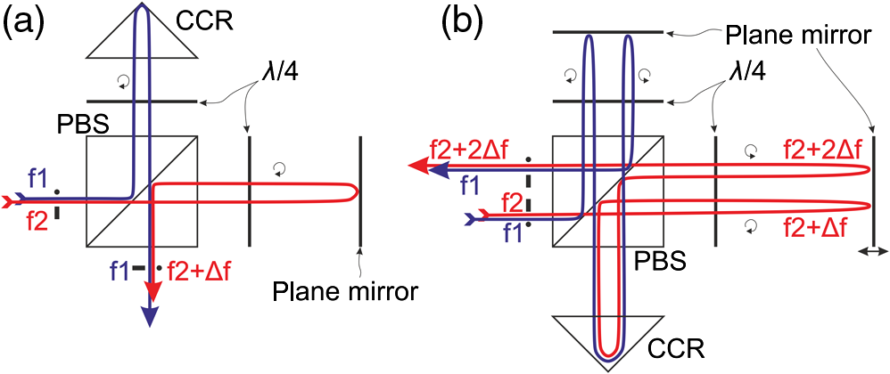
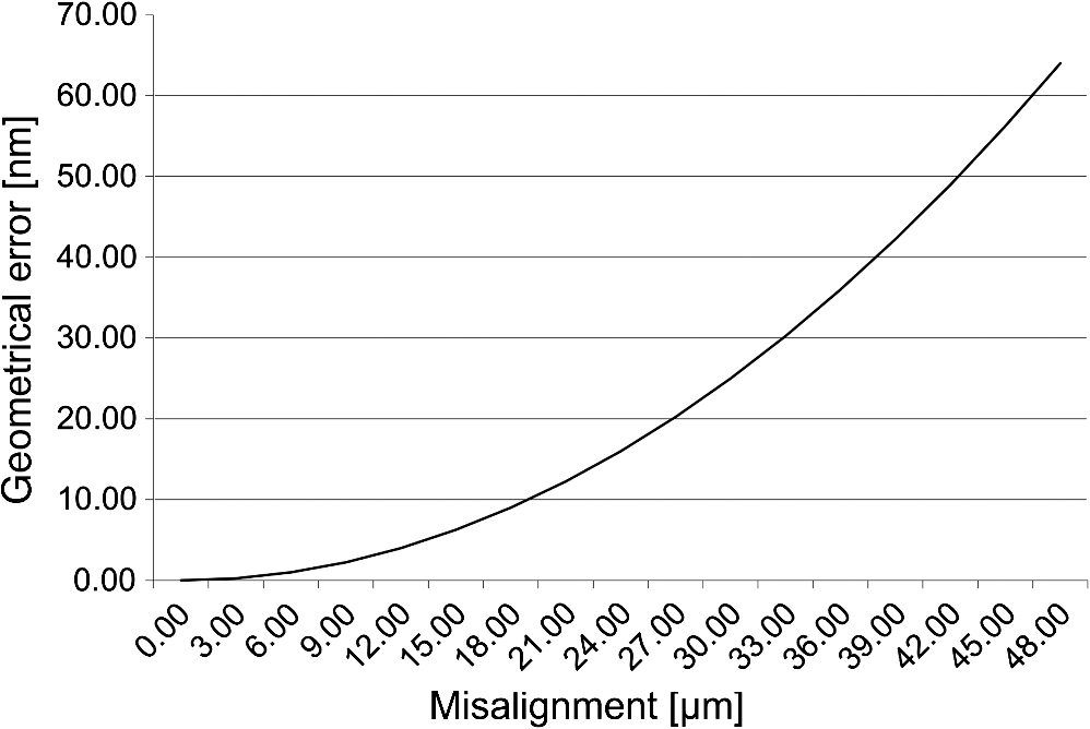
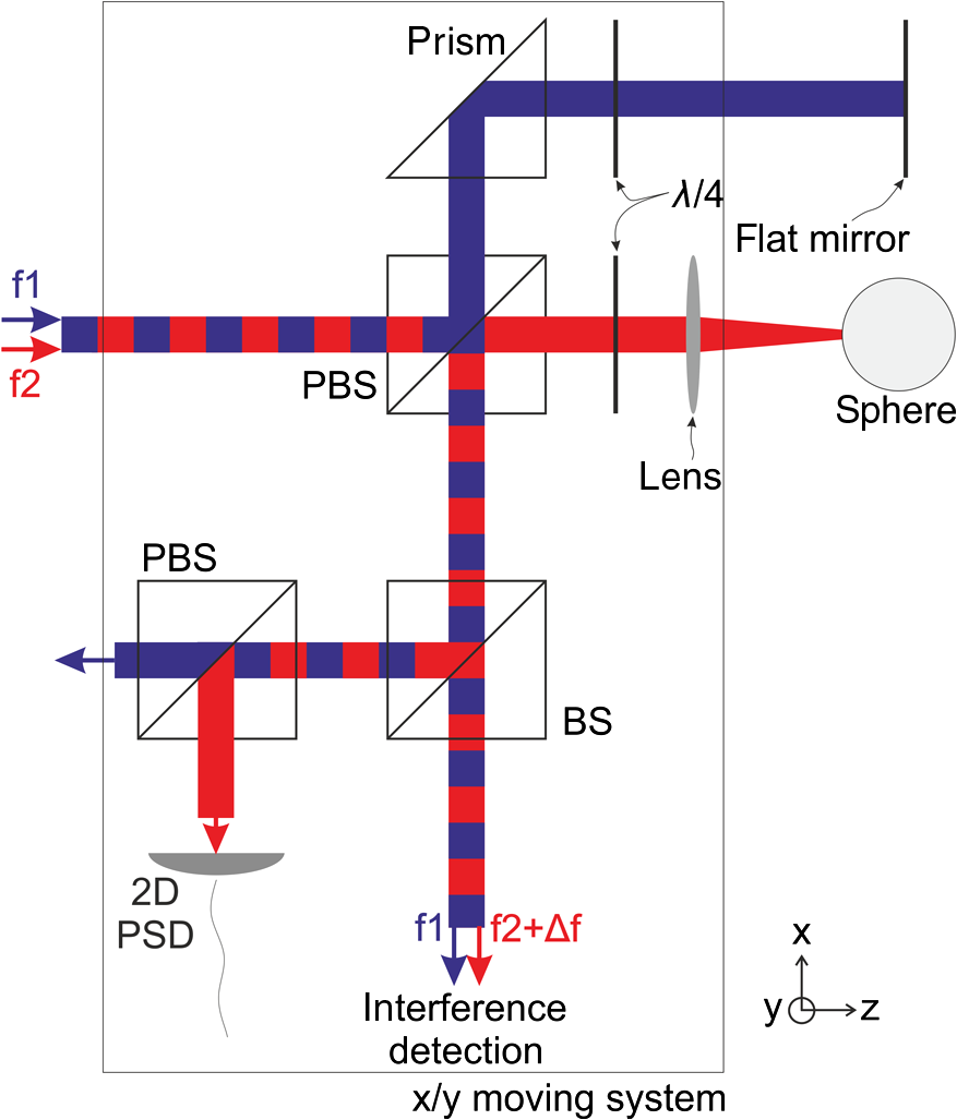
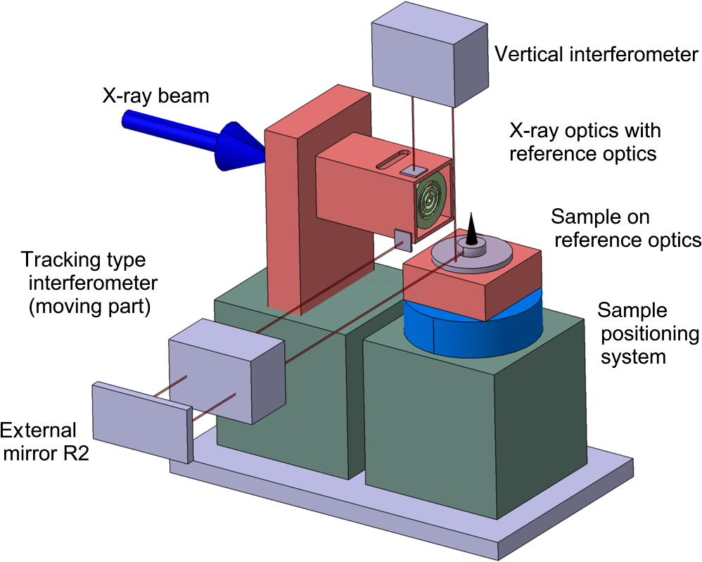
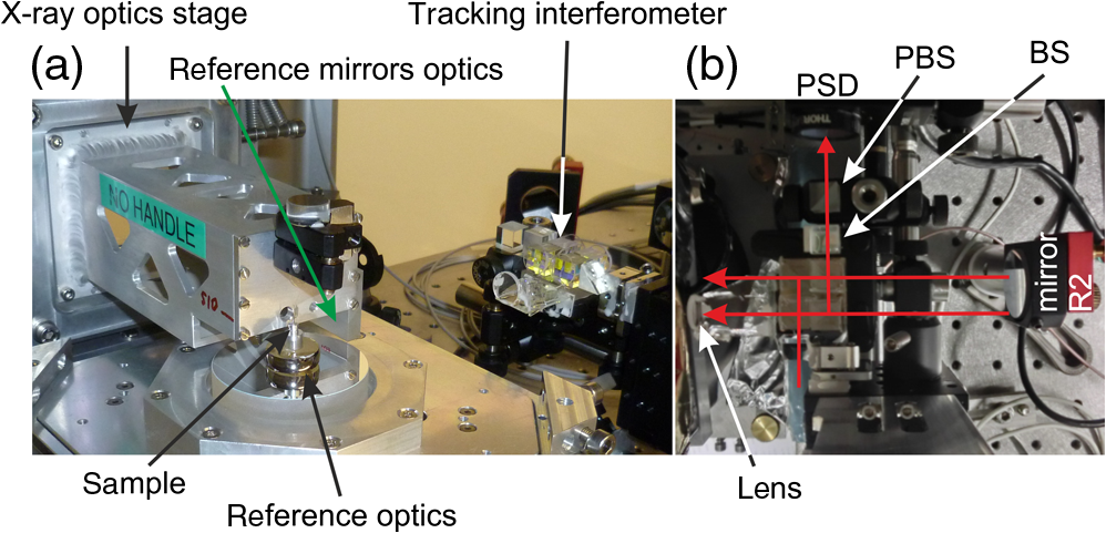
1.IntroductionHeterodyne laser interferometry is widely used for position metrology and control in research and industry. It has clear benefits over other position metrology solutions as it provides long-term stability and accuracy, an intrinsically linear scale, a long measurement range, and is adaptable to different types of measurement applications.1,2 These metrology systems are typically based on a stabilized helium–neon laser operating at 632.8 nm wavelength that provides a heterodyne beam, meaning two orthogonally polarized beams at slightly different frequencies, f1 and f2. The beating frequency, f1–f2, is usually in the range of a few MHz and can be electronically detected when having the two beams interfere on a photodiode. For metrology applications, the two beams (f1 and f2) are separated to form two measurement paths of the interferometer. A change in length of either path generates a Doppler shift of the optical frequency which results in a changed beating frequency of the combined interfering beams. The change in frequency is proportional to the velocity of the change in path length. By comparing the shifted frequency with the unchanged reference frequency of the laser, the change in path length can be determined. Heterodyne laser sources, interferometer optics, and electronics are commercially available; for example from Zygo Corporation or Keysight Technologies. 2.Typical Interferometer Setups2.1.Corner Cube InterferometersIn its simplest form, an interferometer is made up of a beamsplitter (BS) and two corner cube reflectors (CCRs) as illustrated in Fig. 1(a). Fig. 1(a) Corner cube interferometer, (b) modified from (a) for differential or angular measurements. 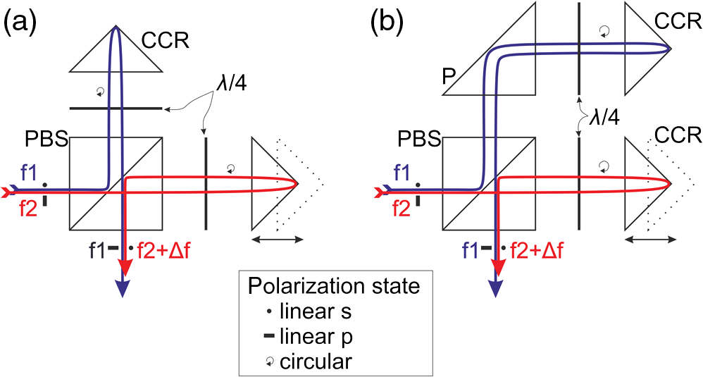 Since the heterodyne beams have orthogonal polarization, the optics of the interferometer has to be polarization-dependent. A polarizing beamsplitter (PBS) is, therefore, used to separate the two laser beams with frequencies f1 and f2, building the start point of the measurement paths. Quarter waveplates in the measurement paths are used to rotate the beam polarization in order to switch their reflectivity behavior on their return to the PBS. As an example, the beam propagating in the upward direction in Fig. 1(a) is first reflected by the PBS, meaning it is s-polarized. After passing the quarter waveplate once, the polarization in the measurement path is circular. On the way back, the polarization is rotated linear again by the quarter waveplate, but it is now p-polarized such that the beam is not reflected, but transmitted by the PBS. For the detection of the beating signal of the recombined beams, a polarizer at 45 deg and a photodiode can be used. This simple version of an interferometer provides a linear displacement measurement of the CCRs with respect to the BS. By rotating one of the measurement beams by 90 deg, for example by using a prism (P), as illustrated in Fig. 1(b), two parallel measurement beams are created, resulting in a differential measurement between two individually moving objects or in an angular measurement in case both CCRs are mounted on a common support. Such types of differential interferometers are insensitive to movements parallel to the measurement direction. Translations of the interferometer (PBS and P) or the CCRs perpendicular to the measurement direction result in a shift of the output beam, and hence a decrease in measurement signal or even signal loss when the detector no longer intercepts the beam. 2.2.Plane Mirror TargetsThe disadvantage of interferometers based on corner cubes is the limited transverse movement capability of the measurement mirrors with respect to the BS optics. Even simple applications such as the measurement of -stage systems require such a degree of freedom. When using plane mirrors instead of corner cubes, as illustrated in Fig. 2(a), such transverse movements are tolerated. In order to observe the signal-generating temporal interference (i.e., beat frequency), rather than a spatial fringe pattern smearing out such a signal on the detector, the plane mirror must be aligned perpendicular to the beam with wavelength precision. When assuming a beam size of 3 mm and accepting a shift of a quarter wavelength, the angular alignment of the plane mirror has to be perpendicular to the beam within . This strict alignment requirement can be relaxed by modifying the interferometer design to include a corner cube in the plane mirror interferometer as depicted in Fig. 2(b). The resulting double-pass interferometer combines the simple alignment of the CCR-based interferometers illustrated in Fig. 1 and the transverse movement capability offered by the plane mirror. The resolution is also doubled because the beams propagate through the interferometer twice. A tilt of a plane mirror results in a pure shift of the output beam, while the wavefront remains untilted. The parallelism of the output beams is maintained making this interferometer tolerant against angular alignment errors of the plane mirrors which have to be perpendicular to the beam propagation within mrads instead of microrads. 2.3.Rotating TargetsThe interferometers presented thus far enable the measurement of translating targets, but also small-range angular measurements are possible. However, for the interferometric measurement of spindles, the target mirror will be rotating and hence requires further modifications to the interferometer design. This is especially true for measurements perpendicular to the axis of rotation where a mirror with rotational symmetry, such as a cylindrical or spherical mirror, is required. Figure 3(a) shows a simple, single-pass interferometer including a rotating target. A lens or lens system focuses the interferometer beam onto the rotating mirror, with the focus being at the rotation center. This allows obtaining an interferometer signal at all rotation angles. Thereby, the focus of the beam may be placed at the surface, resulting in a small measurement spot, or at the center of the spherical target mirror, resulting in a larger spot on the surface and making the system more tolerant against mirror surface imperfections. Though the depicted interferometer is single-pass, the focused geometry makes its alignment tolerant against alignment errors,3 such that alignment requirements are comparable to the previously presented double-pass interferometer. Fig. 3(a) Interferometer for including a rotational measurement, (b) beam deflection off of a spherical mirror. 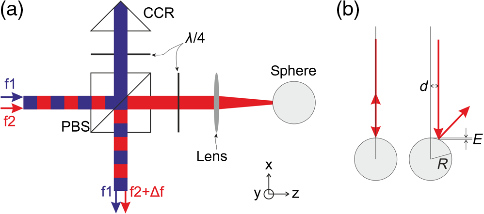 The measurement range along the beam propagation direction is limited by the focused geometry. Restricting the target mirror is to move within the depth of focus of the beam. A prerequisite for measuring a rotating target is that the rotating mirror must be precisely centered on the axis of rotation. Techniques for measuring under this condition are well-known.3 If the mirror is not well-centered, then the resulting wobble motion causes the wavefront to become tilted (reducing the interferometer signal) and in extreme cases can even cause the reflected beam to not propagate back into the interferometer, as illustrated in Fig. 3(b). 3.Tracking InterferometerThe previously described interferometer for rotating targets provides a measurement of a spindle position if the rotating target is well-centered on the axis of rotation and if it is not moving transverse to the measurement beam. The interferometer cannot be applied in more general applications that may be having rotational and translational degrees of freedom, or in cases where the spherical target mirror cannot be precisely centered on the axis of rotation. Certainly, when using a cylinder as rotating target, translational movements of the target system along the cylinder axis, the -direction, are possible, but result in a change of measurement position along the cylinder. As such mirrors are difficult to manufacture, a new measurement spot typically results in a different surface shape and roughness and is therefore not desirable. Additionally, a cylinder requires to not only be centered on the axis of rotation, but also requires its axis to be parallel to the axis of rotation, which presents an additional alignment challenge. On the other hand, measurements on a spherical target mirror must be performed at the equator plane, which does not require an angular alignment. However, this implies that the measurement beam must always point at the center of the spherical mirror to have the beam propagate back to the interferometer. As already mentioned, the focused geometry is relatively tolerant against alignment errors. To which level the beam pointing needs to be preserved, or in other words, how well the spherical target needs to be centered to the axis of rotation, depends mainly on the acceptable measurement error introduced by the spherical mirror geometry which is given by where is the radius of the sphere and is the parallel displacement of the beam with respect to the center of the sphere [see Fig. 3(b)].Figure 4 shows a plot of the geometrical error for a sphere diameter of 36 mm. In this case, beam pointing errors of few microns are acceptable to keep the geometrical error below 1 nm. 3.1.Measurement of the Sphere CenterTo allow the measurement of a rotating spherical target mirror that is not centered on the axis of rotation or that is moving in space, the interferometer beam has to maintain its pointing at the center of the sphere, which in the first step requires the center of the sphere to be measured in the directions perpendicular to the beam propagation direction . The measurement resolution should be better than for this position measurement in order to keep the geometrical error of the interferometric measurement small for a 36-mm diameter spherical mirror (Fig. 4). Figure 5 illustrates how such a measurement can be realized in an interferometer and further details can also be found in Ref. 4. The output beams of the interferometer, i.e., after the PBS, have orthogonal polarization, which allows them to be separated again by a second PBS. Before doing so, the interferometer depicted in Fig. 5 splits the output beam using a nonpolarizing BS. In one of the generated output beams, the interference signal is normally generated, using a polarizer at 45 deg and detected on a photodiode. In the other output beam, the two polarizations are separated by a PBS and the position of the beam reflected off the sphere is detected in a two-dimensional (2-D) position-sensitive detector (PSD). A transverse movement of the sphere with respect to the interferometer results in a change of beam position on the PSD. The resolution that can be obtained depends on the detector and optical geometry, and typically reaches the submicron range. Thus, the interferometer in Fig. 5 measures the position of the sphere with nanometric resolution in the direction and micron resolution in the directions. Fig. 5Measurement of the transverse position of the spherical target mirror using a position sensitive detector (PSD) that can be used to track the center position of the sphere in a closed loop. 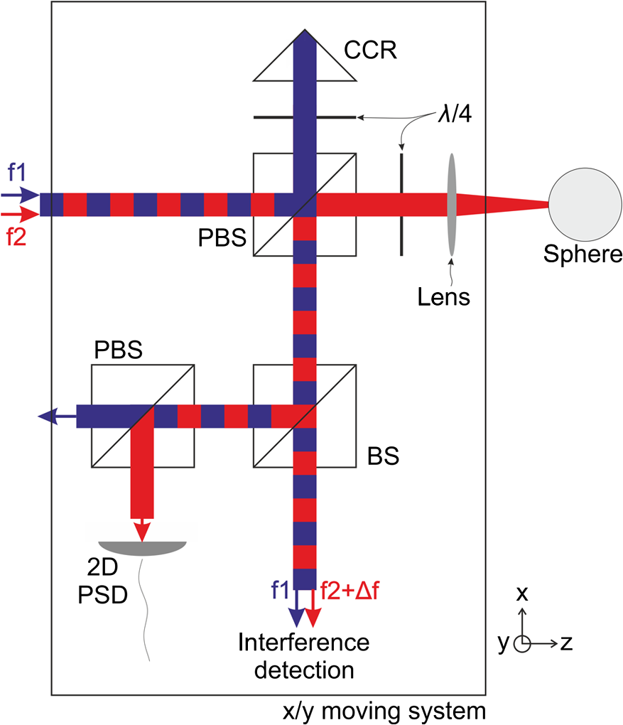 Having the position of the sphere measured in the plane, the interferometer itself can be installed on a translational stage and realigned in a closed loop using the PSD signal to keep pointing at the center of the sphere. The coupling of the laser into the tracking interferometer must be realized in a way to not affect the pointing of the beam entering the interferometer. Closed-loop tracking of the measurement beam gives the sphere full freedom of movement in the plane. The movement in the -direction remains limited by the depth of focus of the focussed laser beam, which can reach the millimeter range. 3.2.Translational Tracking Stage ErrorsThe interferometer depicted in Fig. 5 provides a measurement of a spherical target with the sphere center being tracked in closed loop using the PSD signal. The interferometric data, however, correspond to the relative position of the interferometer’s PBS and CCR to the sphere. While the rotating target position is to be measured interferometrically in the direction, the interferometer may be moving in the plane for the tracking motion to maintain beam alignment. This tracking motion is an additional source of interferometric measurement error. Mechanical translation systems have translational error motions such that a movement of the interferometer will occur in the direction when the interferometer is moved in the plane. As an example, a ball-bearing system has typical translational error motions in the micron range, which are partially nonreproducible. This parasitic error motion introduces a large uncertainty in the interferometric measurement, and thus deteriorating the measurement precision by many orders of magnitude from the nanometer to the micron range. This issue can be solved by implementing an externally fixed plane reference mirror in the interferometer as depicted in Fig. 6. The resulting interferometer provides a differential measurement between the reference mirror and spherical target. A translational movement of the interferometer in the -direction caused by error motions of the tracking system is thereby compensated. The reference mirror, however, needs precise alignment perpendicular to the interferometer beam, as in a single-pass interferometer. In order to obtain interferometer signal, the tilt of the interfering wavefronts has to below a quarter of the wavelength within the diameter of the laser beam. For a 3-mm beam, this results in an acceptable alignment error . The remaining alignment error will produce a constant slope error when the tracking system is moving in the plane, which could be alleviated by using a corner cube instead of the plane mirror, which however will limit the tracking range drastically as the reflected beam will spatially shift, and reducing the beam overlap in the interferometer output. 3.3.Rotational Tracking Stage ErrorsIn addition to translational error motions, a tracking stage system also displays parasitic angular error motions. A typical ball-bearing system shows angular errors in the tens to hundreds of microradians. Just like the interferometer presented in Fig. 1(b), the tracking interferometer of Fig. 6 is measuring these angular changes and is therefore prone to angular error motions, while it is most sensitive to the rotation around the -axis due to the separation of the beams. For example, a rotation results in an error of the position measurement of 100 nm in case of a small beam separation of 10 mm. Note that these are a separate issue from the alignment of the flat mirror in a single-pass interferometer itself. An optical compensation of these error motions is required in order to use a tracking interferometer for measurements in the 1-nm range. For a demonstration of the angular error motion sensitivity, the interferometer shown in Fig. 7(a) was built. It corresponds to the interferometer of Fig. 6 with the lens system and sphere target replaced by a plane mirror. The interferometer was installed on a Thorlabs MT1-Z8 translation stage and repeatedly moved back and forth along the -direction. Interferometric position data were obtained at 0.05 mm intervals using a Hewlet Packard laser Model 5517A, an optical receiver module E1709A, and an N1231A PCI interferometer card, both from Agilent Technologies (now Keysight Technologies). The beam separation in the interferometer was 15 mm. The Thorlabs MT1-Z8 stage specification states 200 microrad angular error motions and was operated without backlash correction. From this specification, a geometrical measurement error of can be expected. Fig. 7(a) Interferometer from Fig. 6 with the sphere being replaced by a plane mirror for demonstrating the sensitivity to angular error motions of a tracking mechanism. (b) Experimental result.  Figure 7(b) shows in red the interferometer readout when moving in the positive direction, while the blue data points correspond to a movement in the negative direction. In the plot, the blue lines are shifted by to the side for better visibility of the red data points. The blue and red data points were taken at identical nominal stage positions. Many cycles were performed to obtain statistical information. The width of the data distribution is caused by environmental noise and nonrepeatable errors of the translation stage. The typical distribution width ranges from 1 to peak to peak and one can clearly see that the stage shows a different behavior when moving in the positive or negative direction. The blue and red lines are separated by up to and the separation strongly depends on the actual stage position. As a consequence, in a tracking interferometer, this angular error motion would limit the measurement accuracy to a few microns instead of the desired nanometer range. 3.4.Optical Error CompensationThe interferometer depicted in Fig. 8 is a modified version of the tracking interferometer allowing for translational and angular errors of the tracking mechanism to be optically compensated. For this, an optical measurement is performed to two external flat reference mirrors. The laser beam enters the interferometer and is split by a polarizing beamsplitter PBS1. The reference beam (blue in Fig. 8) propagates to the reference mirror R1 and back to PBS1 while passing a quarter waveplate twice, resulting in a 90-deg rotated polarization. The beam is, therefore, transmitted by PBS1 and PBS2. It is returned again to PBS2 by reference mirror R2, with two passes through another quarter waveplate and is, therefore, then reflected by PBS2. It then passes a half waveplate and is transmitted by PBS4 to recombine with the measurement beam. The propagation of the measurement beam is similar. It is first transmitted by PBS1, then reflected by PBS3, bounced off the measurement target, and then transmitted by PBS3 and PBS4. After the reflection at the reference mirror R2, it is recombined with the reference beam in PBS4. Please note that even though here four polarizing beamsplitters are employed, this is not needed. When removing PBS2 and PBS4 from the setup, the interferometer functionality remains and the shift of the output beam compared to the input beam is removed. The measurement results presented were obtained with the four beamsplitter versions of the interferometer. The propagation lengths within the interferometer are constant such that the effective propagation path for the reference beam is and for the measurement beam . The optical path difference and measurement signal are therefore given by . Error motions caused by a tracking movement of the interferometer between the two reference mirrors are now optically compensated. For the simplest case, let us assume a translational movement of of the interferometer toward the measurement target. The optical paths and are shortened by , while the paths at and are extended by the same amount. Thus, the interferometer output is unchanged. This translation can also be understood as a rotation with the point of rotation at infinity. Let us move this rotation point to another extreme case, the center of the interferometer plate, and rotate in a clockwise direction. Here, the optical paths are shortened at and , but extended at and . The resulting path difference is, therefore, unchanged . Although the interferometer is a single-pass design, the alignment of the external reference mirror R2 is not critical as it represents a common mirror surface. A tilt of that mirror causes a shift of the output beams, but their parallelism is preserved. However, a tilt of R2 is measured by the interferometer, meaning this surface has to be angularly stable. Also note that compared to the previous design of the tracking interferometer, the interferometer of Fig. 8 is optically balanced and therefore thermally stable. Both beams, the reference and measurement beams, propagate through the same amount of material, apart from the lens which would require a window to be implemented in reference path . The previous experiment presented in Sec. 3.3 was now repeated using the optically compensating design, while again the spherical target and lens are replaced by a flat mirror. The result is depicted in Fig. 9. The interferometer signal is now independent of the direction of motion, i.e., the blue and red data points overlap. The peak-to-peak data within one position are decreased from approximately in the previous case to approximately 50 nm peak to peak and are attributed to environmental noise, mainly air fluctuations. The remaining slope is caused by the tilt between the reference mirror R1 and the flat measurement mirror that replaced the spherical target. Fig. 9Test results for an interferometer optically compensating translational and rotational tracking errors. 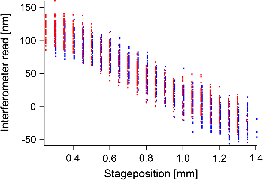 The overlap of blue and red data demonstrates the optical compensation of the interferometer compared to the previous case of Fig. 7(b), where their separation was up to . The separation in the compensated case is still present but reduced to around 15 nm, by a factor of 200 less. This makes it now possible to apply the tracking scheme for nanometric measurements, while error motions of the tracking mechanism in the 20-microrad regime would be acceptable to introduce an error in the interferometric measurement on the 1 nm scale. 4.Application in Scanning X-Ray TomographyIn conventional x-ray imaging, an object is illuminated by an x-ray beam and imaged by a lens system to a 2-D detector, where an absorption image can be recorded. However, to image thicker objects, only multi-keV x-ray radiation provides sufficient penetration power. The x-ray wavelengths are then in angstrom range, and hence imaging resolution is currently limited by the optical aberrations caused by the x-ray imaging system. In contrast, a lensless scanning technique, ptychographic x-ray imaging, was recently demonstrated,5 where resolution is obtained from far-field diffraction patterns generated by illuminating a small region of a specimen. The specimen is moved through the beam and such diffraction data are recorded at many overlapping positions, which can be analyzed by iterative phase retrieval algorithms reconstructing the complex object and x-ray wavefront. The technique requires an accurate sample positioning better than the imaging target resolution, which is currently in the sub 10-nm range. Ptychography can be applied in three-dimensional (3-D) via computed tomography, where many projections of a sample are recorded at different sample orientations. From an instrumentation point of view, this requires sample positioning with nanometric accuracy, including a rotational degree of freedom. To illuminate the sample at a small region, the x-ray beam can be focused by a Fresnel zone plate. The position of the beam is, in this case, mainly determined by the position of the x-ray lens. In order to accurately determine the position of the x-ray beam on the sample, a differential position measurement between the sample (including its rotational degree of freedom) and the x-ray lens must be performed in the two directions perpendicular to the x-ray beam propagation. Laser interferometry provides the required resolution and accuracy, but until now has struggled to cope with rotating targets. The optically compensating tracking interferometer presented in Sec. 3.4 is ideally suited for such x-ray imaging experiments as the rotating sample position can be measured by installing a rotating spherical target mirror at the sample position. Figure 10 presents a schematic of an x-ray tomography microscope that includes robust interferometric positioning. The axis of rotation is vertically aligned, meaning that the vertical position can be measured by a double-pass interferometer [see Fig. 2(b)], when installing a flat mirror perpendicular to the axis of rotation on the rotation stage. The horizontal position can be measured using the tracking interferometer (Fig. 8), which gives full freedom of movement to the spherical mirror target. This allows a sample to be mounted very close to the reference mirrors, which significantly reduces residual thermal drift of the setup. Although this arrangement results in a wobble motion of the spherical target when rotating around the sample position (as the sample will not be perfectly centered on the spherical mirror), the tracking interferometer will follow the center of the sphere and will provide interferometic data at all rotation angles. The reference mirror R1 of the tracking interferometer (Fig. 9) should be installed at the position of the x-ray lens, which directly results in the desired differential measurement of the sample versus x-ray lens position. Figure 11 shows an actual realization of such an instrument, with an overview in Fig. 11(a) showing the sample on the reference surface with the tracking interferometer on the side and Fig. 11(b) showing a close-up top-view of the tracking interferometer. Such interferometry is a key element in the instrument presented in Ref. 6, and has recently allowed reaching an unmatched isotropic 3-D resolution in x-ray tomography of 16 nm in a thick test object.7 5.ConclusionIn this manuscript, several heterodyne laser interferometers have been presented, developing stepwise a tracking-type interferometer that allows the measurement of a rotating target perpendicular to the rotation axis. The tracking mechanism removes the need of the rotating mirror to be center on the axis of rotation. The rotating mirror may wobble or even translate in space. An important key element of the tracking interferometer is the all-optical compensation of error motions of the mechanical tracking mechanism which is achieved by an additional external reference mirror and permits nanometric measurement of the rotating target. The application of the tracking interferometer has been demonstrated in a scanning x-ray tomography system. AcknowledgmentsWe thank the Swiss National Science Foundation SNF for the support of the development of a nanotomography instrument (R’EQUIP, No. 145056, “OMNY”) and the Competence Center for Materials Science and Technology (CCMX) of the ETH-Board, Switzerland. ReferencesG. E. Sommargren,
“A new laser measurement system for precision metrology,”
Precis. Eng., 9
(4), 179
–184
(1987). http://dx.doi.org/10.1016/0141-6359(87)90075-4 PREGDL 0141-6359 Google Scholar
V. Badami and P. de Groot,
“Displacement measuring interferometry,”
Handbook of Otpical Dimensional Metrology, 157
–238 Taylor & Francis, Boca Raton
(2013). Google Scholar
“Non-contact Measurements with Laser Interferometers,”
325
–312 Hewlett Packard Company, Application Note pp. 1997). Google Scholar
M. Dierolf et al.,
“Ptychographic x-ray computed tomography at the nanoscale,”
Nature, 467
(7314), 436
–439
(2010). http://dx.doi.org/10.1038/nature09419 NATUAS 0028-0836 Google Scholar
M. Holler et al.,
“An instrument for 3D x-ray nano-imaging,”
Rev. Sci. Instrum., 83
(7), 073703
(2012). http://dx.doi.org/10.1063/1.4737624 RSINAK 0034-6748 Google Scholar
M. Holler et al.,
“X-ray ptychographic computed tomography at 16 nm isotropic 3D resolution,”
Sci. Rep., 4
(3857),
(2014). http://dx.doi.org/10.1038/srep03857 SRCEC3 2045-2322 Google Scholar
|