|
|
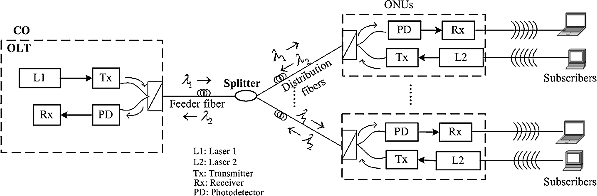
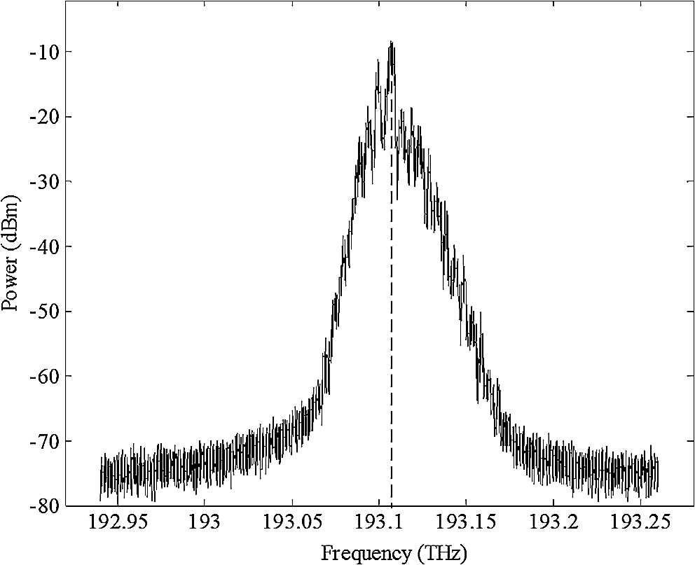
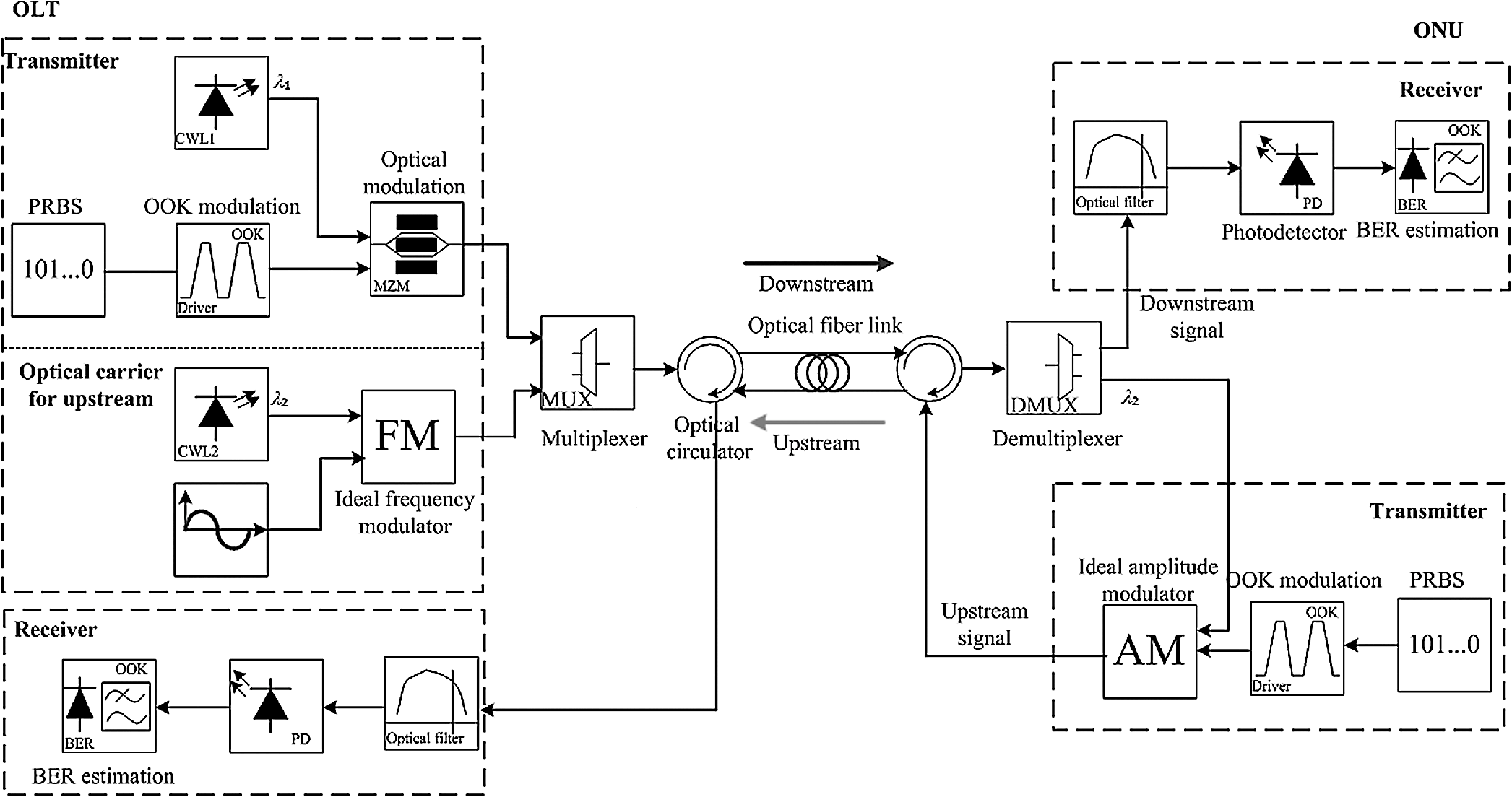
1.IntroductionRecently, the last-mile broadband access network has faced severe design challenges as new bandwidth-hungry applications (e.g., online games, and so on) are constantly emerging. If we want to satisfy such growing bandwidth requirements by using traditional access technologies, the limitations of capacity and flexibility, as well as the high expenditure will become obstacles. Since the passive optical network (PON) has the unique advantages of high-bandwidth provisioning, low-quality loss, and antielectromagnetic interference, it has become a promising solution for next-generation fiber-to-the-home access networks.1–5 According to different optical network unit (ONU) multiplexing methods, PON can be divided into three main groups: time-division-multiplexing PON (TDM-PON), wavelength-division-multiplexing PON (WDM-PON), and TDM/WDM-PON.6 Among them, TDM-PON has been widely used owing to its mature technology and low cost.7–9 The TDM-PON can utilize direct or coherent detection to receive optical signals. Direct detection is easy to implement and can efficiently realize dispersion compensation.10 In addition, the receiver design followed by coherent detection is quite complicated, although it has high-receiver sensitivity and spectral efficiency to combat polarization-mode dispersion. Thus, for the practical implementation of TDM-PONs, we urgently need to combine intensity modulation with direct detection since this combination is able to reduce system installation and maintenance costs. However, the current intensity-modulation and direct-detection TDM-PON suffers from some problems such as the following: First, the use of directly modulated lasers (DMLs) is preferable because it can achieve low cost, good compactness, small driving voltage, low-electrical power consumption, and high-output optical power.11,12 Thus, the DML-based intensity-modulation and direct-detection TDM-PON (system 1) was developed.6 In system 1, a long-transmission distance and a high-splitter ratio are usually ensured so that subscribers can be efficiently accommodated. However, the increased transmission distance and splitter ratio actually incurs high-insertion loss. Therefore, mitigating this power penalty is a major challenge. Meanwhile, we should restrict the power penalty without degrading the bit error rate (BER). In the previous work collaboratively accomplished by us and State Grid Electric Power Supply Companies in Shenyang,6 a simple schematic of system 1 and some simulations were merely mentioned. In this paper, we additionally design a VPI (an optical simulation software developed by VPIphotonics company)-based architecture with working principles for system 1, as well as make an extensive and deep simulation analysis for solving the aforementioned challenge. More importantly, we also achieve system 2 as presented later and analyze its performances via the VPI simulator. Next, in the upstream direction, all ONUs share a single-wavelength channel and send their own data via a feeder fiber by using TDM technology. However, each ONU needs one laser source in its transmitter, which increases the system cost and complexity. For this end, intensity-modulation and direct-detection TDM-PON using a colorless ONU (system 2) was also developed. Here, we define the colorless ONU as the ONU that is not equipped with a laser source to generate the optical carrier for the upstream transmission. Instead, the laser source laid in the optical linear terminal (OLT) is shared by all ONUs for the upstream transmission. To implement a colorless ONU, several methods were designed.13–15 However, once the colorless ONU is introduced, Brillouin backscattering (BB)16,17 becomes worse. To solve the aforementioned problems, these two systems are established via VPI simulators18 as follows: (1) we analyze the influence on the system 1 performances, which mainly includes the BER and power penalty, and a low-power penalty is guaranteed without degrading the BER of system 1, and (2) using an empty carrier generated by an OLT along with the downstream signal for upstream transmission, we achieve a colorless ONU in system 2. For system 2, we propose phase modulation of the optical carrier to reduce the BB effect. The simulation results show that our study provides valuable references for next-generation PONs. These two systems utilize an off-the-shelf TDM-PON protocol. The rest of this paper is organized as follows. In Sec. 2, we introduce the proposed systems based on VPI simulators, and the main factors affecting the system performance are analyzed. The simulation results are discussed in Sec. 3. Finally, we conclude this paper in Sec. 4. 2.System ArchitectureBefore discussing the architecture of system 1 (DML-based intensity-modulation and direct-detection TDM-PON) and system 2 (intensity-modulation and direct-detection TDM-PON using colorless ONUs), we briefly introduce the traditional TDM-PON architecture.6 Figure 1 shows that the traditional TDM-PON architecture has a tree topology with the central office located at the root and the subscribers connected to the leaf nodes of the tree. It connects the OLT to multiple ONUs through a feeder fiber and distribution fibers. In addition, it has upstream data (from ONUs to OLT) and downstream data (from OLT to ONUs) operated in two separate wavelength channels. Using a splitter, the optical signal at wavelength channel from the OLT is split into multiple ones, each of which is destined to an ONU. Every ONU is equipped with a laser source of wavelength and transmits its data using TDM technology. Compared with traditional TDM-PONs, the two systems achieved in this paper have the following merits: For system 1: (1) the combination of intensity modulation and direct detection is able to reduce system installation and maintenance costs. (2) It utilizes DMLs to guarantee the low cost, good compactness, small driving voltage, low-electrical power consumption, and high-output optical power of TDM-PONs. (3) We restrict the power penalty without degrading the BER of system 1. In addition to the first metric of system 1, we also deploy the colorless ONU without a laser source to generate the optical carrier for the upstream transmission, which reduces the cost of system 2. The phase modulation of the optical carrier is also achieved in system 2 in order to reduce the BB effect. In the following, we will describe these two systems in detail. 2.1.System 1In this subsection, we introduce the architecture of system 1 in terms of working principle and impact factors. 2.1.1.Architecture and working principleFigure 2 shows the schematic of the DML-based intensity-modulation and direct-detection TDM-PON (system 1), which includes three parts: transmitter, receiver, and optical-fiber link with a variable optical attenuator (VOA). In the transmitting side, we perform an on–off keying (OOK) modulation (OOK driver module in Fig. 2) on the pseudo random binary sequence (PRBS) to generate the electrical signal . Then this electrical signal is utilized to modulate the DML, such as a distributed feedback (DFB) laser, according to the single-mode rate equation (SM RE module in Fig. 2). The output power and phase are determined according to Eqs. (1)–(5).19 More specifically, Eqs. (1) and (2) denote the transient carrier density and photon density of the DFB laser, respectively. Equation (3) represents the optical power of the output optical signal with the frequency . The transient phase of the output optical signal is shown in Eq. (4), and Eq. (5) records the frequency of the output optical signal. where is the carrier density, is the photon density, is the central frequency of the optical carrier, is the output optical power at frequency with respect to , is the output optical phase at frequency with respect to , is the total electric current injected to the active region of the DFB laser, is the volume of the aforementioned active region, is the electronic charge, is the linear carrier recombination lifetime, is the bimolecular recombination coefficient, is the Auger carrier recombination coefficient, is the linear optical gain coefficient, is the transparency carrier density, is the nonlinear gain coefficient, is the mode confinement factor, is the fraction of spontaneous emission emitted into the fundamental mode of the laser, is the photon lifetime, is the optical coupling coefficient, are the vertical widths of the guided-mode power distributions, are the horizontal widths of the guided-mode power distributions, is the Planck’s constant, is the photon frequency, is the velocity of light in vacuum, is the group refractive index, is the phase refractive index, and is the rate of refractive-index change with the carrier density.The generated optical signal is coupled into the optical fiber link and finally arrives at the receiver. The VOA (attenuator module in Fig. 2) is deployed to control the received signal power and to emulate the power loss of the splitter. In the receiving side, a square-law photodetector (PD)-based (PD module in Fig. 2) direct detection is adopted to acquire the electrical signal. The BER and power penalty are respectively analyzed using the BER estimation and the power-penalty-calculation modules shown in Fig. 2. In particular, under a given BER, the power penalty here is defined as the received optical power (ROP) difference between the optical fiber transmission along a specific transmission distance and the corresponding optical back-to-back transmission. Obviously, mitigating the power penalty can improve the system-level power budget. Figures 3 and 4 show the spectrogram at the transmitting and receiving sides, respectively. Figure 3 shows that because of the existence of a nonlinear frequency chirp from the DML laser, a central frequency offset of the optical signal occurs (the previous central frequency , as shown in Fig. 3) after the optical modulation, and the power of the optical signal attenuates at the receiving side, as shown in Fig. 4. Therefore, the nonlinear frequency chirp of the DML laser is an important impact factor on the BER and power penalty. 2.1.2.Impact factorsAccording to Eqs. (4) and (5), the nonlinear frequency chirp of the DFB laser can be determined by Eq. (6), and it is affected by the linewidth enhancement factor of the DFB laser, as expressed in Eq. (7): As mentioned earlier, the BER and power penalty are mainly affected by the DFB laser performance. According to Eq. (7), the linewidth enhancement factor gives rise to the nonlinear frequency chirp of the DFB laser, leading to the deterioration in the BER and power penalty. Here, denotes the adiabatic frequency-chirp coefficient. In addition, the ROP and fiber length influence the performance, which will be presented later. 2.2.System 2In this subsection, we will introduce the architecture of system 2 in terms of working principle and impact factors. 2.2.1.Architecture and working principleOn the basis of the traditional TDM-PON architecture, we propose the intensity-modulation and direct-detection TDM-PON using colorless ONUs (system 2) to further reduce the system cost. From the existing works focusing on reducing the TDM-PON cost,12,20,21 we find that the most popular method of reducing TDM-PON cost is using colorless ONUs. But we must point out that the colorless ONUs were applied to WDM/TDM hybrid PONs in these existing works. In this paper, we deploy colorless ONUs in the pure TDM-PON system, i.e., system 2. In order to guide readers, we compare the cost of WDM/TDM hybrid PONs and system 2. For a 4-wavelength WDM/TDM hybrid PON, four continuous wave lasers (CWLs) are utilized to generate optical carriers for the downstream transmission, while the pure TDM-PON (system 2) only needs one CWL. The price per CWL is about 1600 dollars, so system 2 saves about 4800 dollars. Obviously, system 2 has the lower cost. Figure 5 shows the architecture of system 2. The transmitter of the OLT has two laser sources: CWL at (CWL1 module in Fig. 5), corresponding to the optical carrier of the downstream transmission, and CWL at (CWL2 module in Fig. 5), corresponding to the optical carrier for the upstream transmission. We first perform OOK modulation on the PRBS generated by the transmitting side; then the Mach–Zehnder modulator (MZM) (MZM module in Fig. 5) is adopted to perform intensity modulation on optical carrier . The downstream signal and optical carrier are multiplexed using one multiplexer (MUX module in Fig. 5) and are then transmitted to the ONU side along the optical fiber link. In the ONU side, one demultiplexer (DMUX module in Fig. 5) is used to separate the downstream signal from . After passing through the optical filter, the downstream signal is directly detected by the PD (PD module in Fig. 5). Meanwhile, as the optical carrier for upstream transmission, is modulated by the upstream signal through an ideal amplitude modulator (AM module in Fig. 5). 2.2.2.Impact factorsIn system 2, BB would occur because of the interaction between the incident light waves and phonons during optical fiber communication, thus leading to signal noise. Therefore, to reduce the detrimental effect of BB, we propose phase modulating of the optical carrier . Figure 5 shows an electrical sine waveform to modulate the CWL at using an ideal frequency modulator (FM module in Fig. 5). 3.Simulation Results and DiscussionsIn our simulations, we first focus on the BER and power penalty of system 1. Both are mainly affected by the laser linewidth enhancement factor and fiber length. We also investigate the effect of BB on the BER of system 2. Our simulations mentioned above are all performed using the optical transmission simulator VPI.18 For system 1, the parameter settings of the DML laser are listed in Table 1. In systems 1 and 2, for the single mode fiber link, the dispersion parameter is , and the attenuation is ; the responsivity of the PD is , and the thermal noise is . Table 1Parameter settings of the directly modulated lasers.
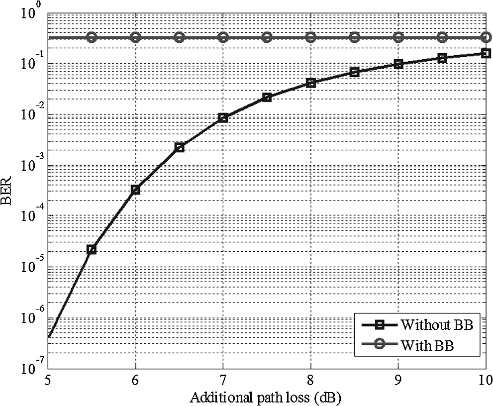
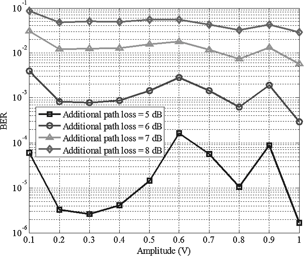
3.1.Simulation Results of System 1Figure 6 shows the relationship between the ROP and BER under different fiber-length scenarios when the linewidth enhancement factor is equal to three. Figure 6 shows that the BER becomes better with the increment in the ROP. With the increase in the fiber length, the nonlinear frequency chirp of the DML becomes more serious, thus leading to a worse BER. When the fiber length is 25 km, the BER can still reach the forward error correction (FEC) limitation of , which indicates an error-free transmission. Fig. 6Bit error rate (BER) versus received optical power (ROP) at different fiber lengths when the linewidth enhancement factor is equal to three. 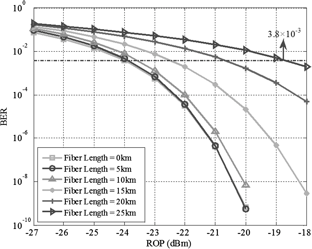 When the fiber length is equal to 20 km, Fig. 7 shows the relationship between the ROP and BER under different linewidth enhancement factors. Figure 7 shows that the linewidth enhancement factor plays an important role in worsening the BER. With the increase in the linewidth enhancement factor, the BER becomes worse because the nonlinear frequency chirp of the DML becomes more serious, leading to a higher BER. However, when the linewidth enhancement factor is 3.5, the BER can still satisfy the FEC limitation. Fig. 7BER versus ROP at different linewidth enhancement factors when the fiber length is equal to 20 km. 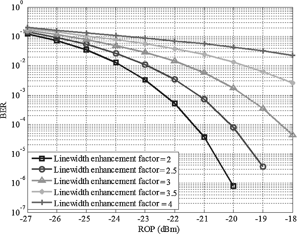 Figure 8 shows the relationship between the linewidth enhancement factor and power penalty under different given BERs when the fiber length is 15 km. Figure 8 shows that the power penalty follows a rising trend with the increase in the linewidth enhancement factor because the nonlinear frequency chirp of the DML becomes more serious, resulting in a higher ROP to ensure the given BER requirement for the 15-km fiber transmission. Moreover, the maximal power penalty is 4 dB when the linewidth enhancement factor varies from two to four for the 15-km fiber transmission that guarantees the BER requirement of , which means that we can realize a low-power penalty without degrading the BER of system 1. Fig. 8Power penalty versus linewidth enhancement factor under different given BERs when the fiber length is equal to 15 km. 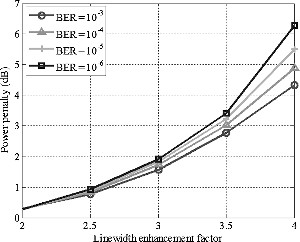 Figure 9 shows the relationship between the fiber length and power penalty under different given BERs when the linewidth enhancement factor is equal to three. The power penalty also follows a rising trend with the increase in the fiber length. The reason for this is that with increasing fiber length, the nonlinear frequency chirp of the DML becomes more serious, thus leading to a higher ROP to satisfy the given BER requirement for fiber transmission. Moreover, the maximal power penalty is 6 dB when the fiber length varies from 1 to 25 km while guaranteeing the BER requirement of . This demonstrates that we can realize a low-power penalty without degrading the system BER. 3.2.Simulation Results of System 2Figure 10 shows the BER of the upstream transmission against the additional path loss caused by connectors or a nonideal splitter with and without BB. As expected, the BER degrades with increasing additional path loss. In addition, the BB seriously degrades the BER. Next, we perform phase modulation of the optical carrier using an electrical sine waveform (as shown in Fig. 5) to reduce the BB effect. We use the amplitude to denote the peak amplitude of the sine waveform. The BER under different amplitude settings is shown in Fig. 11. By comparing the BER results in Figs. 10 and 11, we can see that phase modulation can effectively improve the BER. For example, when the additional path loss is equal to 5 dB, the BER with the BB effect approaches approximately 0.33, as shown in Fig. 10, whereas using phase modulation of the optical carrier results in a maximal BER of only , as shown in Fig. 11, when the additional path loss is equal to 5 dB. Finally, Fig. 11 shows that the BER value fluctuates under different amplitudes; hence, we can determine the optimal amplitude value to reduce the BB effect. For example, when the additional path loss is equal to 5 dB, we can determine the optimal amplitude as 1 V, as shown in Fig. 11, because it has the lowest BER. 4.Conclusion and Future WorkIn this paper, we have proposed the DML-based intensity-modulation and direct-detection TDM-PON and the intensity-modulation and direct-detection TDM-PON using colorless ONUs to reduce system cost. The system performance, including the BER and power penalty, was simulated under different conditions for system 1, and the effect of BB on the BER of system 2 was demonstrated under different additional path losses. The simulation results showed the following: (1) the BER becomes worse with a larger fiber length, lower ROP, and higher laser linewidth enhancement factor, (2) the power penalty becomes high when the linewidth enhancement factor and fiber length both increase, and (3) the BB greatly degrades the BER, but phase modulation of the optical carrier can effectively reduce the effect of BB on the BER. Our study results are theoretically significant for next-generation PONs. This paper simulated system performances based on VPI simulators. In the future, we will conduct high-level experiments to support these simulations at actual test sites. AcknowledgmentsThis work was supported in part by the National Natural Science Foundation of China (61401082, 61471109, 61172051), the Fundamental Research Funds for the Central Universities (N140405005, N130817002, N130404002, N120804002), the Foundation of the Education Department of Liaoning Province (L2014089), the Liaoning BaiQianWan Talents Program, and the National High-Level Personnel Special Support Program for Youth Top-Notch Talent. ReferencesA. R. Dhaini et al.,
“Energy efficiency in TDMA-based next-generation passive optical access networks,”
IEEE/ACM Trans. Networking, 22
(3), 850
–863
(2014). http://dx.doi.org/10.1109/TNET.2013.2259596 IEANEP 1063-6692 Google Scholar
M. M. Rad et al.,
“Probing the limits of PON monitoring using periodic coding technology,”
IEEE/OSA J. Lightwave Technol., 29
(9), 1375
–1382
(2011). http://dx.doi.org/10.1109/JLT.2011.2125946 JLTEDG 0733-8724 Google Scholar
N. Sotiropoulos, T. Koonen and H. D. Waardt,
“D8PSK/OOK bidirectional transmission over a TDM-PON,”
in Proc. ICTON,
1
–4
(2012). Google Scholar
E. Harstead,
“Future bandwidth demand favors TDM PON not WDM PON,”
in Proc. OFC,
1
–3
(2011). Google Scholar
Y. Luo et al.,
“Time- and wavelength-division multiplexed passive optical network (TWDM-PON) for next-generation PON Stage 2 (NG-PON2),”
IEEE/OSA J. Lightwave Technol., 31
(4), 587
–593
(2013). http://dx.doi.org/10.1109/JLT.2012.2215841 JLTEDG 0733-8724 Google Scholar
D. Wu et al.,
“Passive optical network system performance analysis using a DML,”
Appl. Mech. Mater., 635–637 1094
–1097
(2014). http://dx.doi.org/10.4028/www.scientific.net/AMM.635-637 AMMPDO 1660-9336 Google Scholar
Y. Luo et al.,
“Symmetric TWDM-PON with DSB OFDM modulation,”
in Proc. OFC,
1
–3
(2014). Google Scholar
D. L. Truong, P. T. Do and A.T. Pham,
“Optimization of survivable mesh long-reach hybrid WDM-TDM PONs,”
IEEE/OSA J. Opt. Commun. Networking, 6
(1), 62
–76
(2014). http://dx.doi.org/10.1364/JOCN.6.000062 Google Scholar
J. M. Buset, Z. A. El-Sahn and D. V. Plant,
“Demonstration of a symmetric 10 Gb/s QPSK subcarrier multiplexed WDM PON with IM/DD transceivers and a bandwidth-limited RSOA,”
in Proc. OFC,
1
–3
(2013). Google Scholar
C. H. Yeh, C. W. Chow and Y. L. Liu,
“Adaptive upstream optical power adjustment depending on required power budget in PON access,”
Opt. Commun., 285
(24), 4927
–4930
(2012). http://dx.doi.org/10.1016/j.optcom.2012.07.049 OPCOB8 0030-4018 Google Scholar
J. Yu et al.,
“Applications of chirp-managed laser in access and metro networks,”
IEEE/OSA J. Lightwave Technol., 27
(3), 253
–265
(2009). http://dx.doi.org/10.1109/JLT.2008.2006064 JLTEDG 0733-8724 Google Scholar
M. A. Elmagzoub et al.,
“Stacked TDM-PON with colorless ONU for NG-PON,”
in Proc. ICP,
250
–252
(2013). Google Scholar
R. Urata et al.,
“High performance, low cost, colorless ONU for WDM-PON,”
in Proc. OFC,
1
–3
(2012). Google Scholar
Z. Zhang et al.,
“C/L-band colorless ONU based on polymer bi-directional optical subassembly,”
IEEE/OSA J. Lightwave Technol., 33
(6), 1230
–1234
(2015). JLTEDG 0733-8724 Google Scholar
Y. Khan et al.,
“Rayleigh backscattering minimization in single fiber colorless WDM-PON using intensity remodulation technique,”
Optoelectron. Lett., 8
(5), 380
–383
(2012). http://dx.doi.org/10.1007/s11801-012-2268-8 1673-1905 Google Scholar
I. V. Bogachkov, S. V. Ovchinnikov and N. I. Gorlov,
“The Brillouin backscattering modeling for analysis of distributed irregularities in optical fibers,”
in Proc. APEIE,
30
–31
(2010). Google Scholar
I. V. Bogachkov and V. A. Maystrenko,
“Experimental examinations of changes influence of the Brillouin backscattering spectrum in optical fibers on their characteristics,”
in Proc. Dynamics,
1
–10
(2014). Google Scholar
X. Zheng et al.,
“Negative power penalties of optical OFDM signal transmissions in directly modulated DFB laser-based IMDD systems incorporating negative dispersion fibers,”
IEEE Photonic J., 2
(4), 532
–542
(2010). http://dx.doi.org/10.1109/JPHOT.2010.2050464 PJHOC3 1943-0655 Google Scholar
G. Valicourt et al.,
“High gain (30 dB) and high saturation power (11 dBm) RSOA devices as colorless ONU sources in long-reach hybrid WDM/TDM-PON architecture,”
IEEE Photonics Technol. Lett., 22
(3), 191
–193
(2010). http://dx.doi.org/10.1109/LPT.2009.2038173 IPTLEL 1041-1135 Google Scholar
M. Huang et al.,
“A novel flexible optical remote node architecture for dynamic wavelength allocation over hybrid WDM/TDM PON systems,”
in Proc. ECOC,
1
–3
(2013). Google Scholar
BiographyXiaoxue Gong received her BS and MS degrees in communication and information systems from Northeastern University, Shenyang, China, in 2011 and 2013, respectively. Currently, she is pursuing her PhD in the same university. Her research interests include next-generation passive optical networks. Lei Guo received his PhD in communication and information systems from School of Communication and Information Engineering, University of Electronic Science and Technology of China, Chengdu, China, in 2006. He is currently a full professor in the College of Information Science and Engineering, Northeastern University, Shenyang, China. His research interests include survivability, optical networks, and wireless mesh networks. He has published over 200 technical papers in the above areas. Yejun Liu received his PhD in communication and information systems from Northeastern University, Shenyang, China, in 2014. Currently, he is an associate professor in the College of Information Science and Engineering, Northeastern University. His research interests include converged wireless-optical communication and optical access network. |