|
|
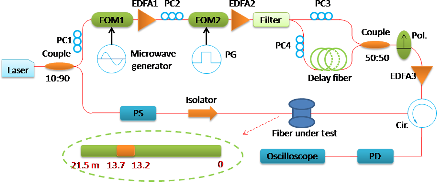
1.IntroductionFor the past decade, distributed optical fiber sensors based on Brillouin optical time domain analysis (BOTDA) have been extensively applied to solve the monitoring of temperature and strain in large structures like pipelines and electrical power cables. This technique is based on the stimulated Brillouin scattering (SBS), in which a pump pulse and counter-propagating continuous probe wave,1 spectrally separated by the Brillouin frequency shift (BFS), interfere and produce an acoustic field through electrostriction that initiates a power transfer between the two optical waves. However, the best attainable spatial resolution of conventional BOTDA is limited down to 1 m,2 attributed to the phonon lifetime (about 6 ns).3 Recently, several pulse-based configurations such as prepumping pulse,4 dark pulse,5 and -phase pulse6 have been proposed aimed at reducing the rapid broadening of the Brillouin gain spectrum (BGS) when shorter pulses are employed. In these pulse-based methods, an apparent Brillouin gain variation on the sensing signal will be observed by using a continuous pump wave to prepump the phonon field before the actual pump pulse arrives and passes through. This visible reflection on the pre-excitation of the steady acoustic wave is called the first echo and its magnitude is determined by the amplitude of the steady acoustic wave generated by the continuous counter-propagating optical waves. In these configurations, a natural Brillouin linewidth is preserved resulting in high sensitivity to temperature or strain and simultaneously providing high-spatial resolution, while suffering from a long lasting second echo giving rise to an inaccurate measurement of the BGS. There are many approaches that try to mitigate the effect of the second echo, such as deconvolution-based method,4 Brillouin gain-profile tracing,7 and four-section dark pulse,8 but the sensing range is limited because the probe wave experiences saturated Brillouin gain contributed by every point of the sensing fiber in the case of a continuous pump wave. After that, many techniques have been proposed to extend the range of BOTDA sensors. One technique9 based on an unbalanced double sideband (DSB) probe wave is reported to mitigate the nonlocal effects induced by pump depletion and a sensing range of 50 km with a 5-m spatial resolution is achieved by this method. Another technique10 based on a DSB modulated probe wave was also recently proposed. With this technique, the pump depletion of the DSB modulation is remarkably suppressed and a longer sensing range is possible according to the theoretical simulation and experimental results. Additionally, configuration based on the differential pulse-width pair BOTDA (DPP-BOTDA)11 is also reported to extend the sensing range and simultaneously achieve submeter spatial resolution, while the measurement time is twice as long as that of the traditional BOTDA. Another novel configuration based on coherent interaction of the Brillouin gain and loss by optical differential parametric amplification (ODPA-BOTDA)12 is proposed to reduce the measurement time by half and avoid the photodetector being saturated since the difference of the signals is directly detected before reaching the photodetector. More recently, our group proposed an improved ODPA-BOTDA13 based on a double-sideband probe wave. In this proposal, submeter spatial resolution and a longer sensing range can be achieved by balancing the power of the two pump pulses. However, the signal-to-noise (SNR) both of ODPA-BOTDA and our improved ODPA-BOTDA is the same as that of traditional DPP-BOTDA configuration, which still limits the sensing range. In this paper, a novel differential Brillouin fiber sensor is proposed in which Stokes and anti-Stokes pump waves are simultaneously phase modulated and delay each other in the time domain to produce a phase difference on the part of Stokes and anti-Stokes pump waves. With this scheme, a probe wave experiences a Brillouin gain only when there exists a temperature or strain change along the sensing fiber. As a result, the photodetector in our proposal is less likely to become saturated and the probe wave’s power can be increased in the case of a longer sensing range. With this technique, the SNR is nearly twice as high as that of the DPP-BOTDA configuration resulting from the -phase shift on the pump wave and an even longer sensing range will be achieved. In addition, a novel fitting method is also proposed in this paper to accurately extract the estimated parameters of the Brillouin scattering spectrum from noisy signals. 2.Theoretical Analysis and SimulationTo validate our concept, a three-section pump pulse as described in Fig. 1(a) is presented for theoretical analysis as described in Ref. 4, in which a general analytic solution of a classical three-coupled equation is presented based on this three-section pump pulse. The first section of the three-section pump pulse with a pump amplitude of and width of is assumed to be long enough to activate the acoustic field, and the middle section with a pump amplitude of and duration of following the first section is the actual pump pulse to obtain Brillouin gain. The last section with a pump amplitude of and infinitely long duration is to balance the Brillouin gain captured by the middle section in our proposal. Then the three-section pump pulse can be described as where stands for the Heaviside unit step function and represents the slowly varying envelope approximation of the anti-Stokes pump if , otherwise the Stokes pump envelope is represented. The schematic model of our technique is described in Fig. 1(b). An anti-Stokes pump wave at frequency and a Stokes pump wave with the same power and polarization at frequency are synchronously launched into the sensing fiber with a phase difference. The duration of the phase difference on the two sidebands determines that the spatial resolution is , where is the velocity of light propagating along the standard SMF. Further, is the modulated frequency altering the nearby Brillouin frequency shift ; and the counter-propagating probe wave at frequency is injected into the far end of the sensing fiber interacting with the double-sideband pump wave at the same time.Fig. 1(a) Schematic diagram of three-section pulse where the pump amplitudes are , , and , respectively and (b) schematic model of our method. There is a phase difference of between the red part and the blue one. The orange arrows represent the direction of energy transfer. The spatial resolution is determined by . 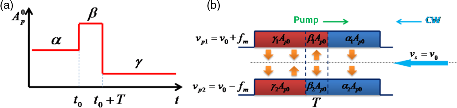 In our configuration, the energy transfers from the anti-Stokes pump wave to the counter-propagating probe wave and then equivalently from the probe wave to the Stokes pump during the first section as described in Fig. 1(b). It should be noted that there will be a remarkable change appearing where the energy is reflected from the probe wave to the anti-Stokes pump wave owing to a phase difference of on the anti-Stokes pump wave when the middle section with a duration of continues its travel through the sensing fiber. Then the energy transfer during the last section will be slowly recovered to the same direction as with the first section. A theoretical solution can be obtained by analytically decomposing the above SBS process into two independent ones. Interaction between the anti-Stokes pump and the probe wave is referred to as a Brillouin gain process, and that between the Stokes pump and the probe wave is referred to as a Brillouin loss process. Further, it can be described by two three-coupled equations with a slowly varying envelope approximation and negligible transverse field variations as following:3 where the Brillouin gain process is described when , and the Brillouin loss process is represented when . The frequency detuning parameter is for , where and are the Brillouin shift frequency and pump-probe frequency difference, respectively. is the slowly varying envelope approximation of the activated acoustic field. is the acoustic damping constant relating to the full width of half maximum of the BGS by , where is the lifetime of the acoustic wave approximating to 6 ns3 in a standard SMF. and are electrostrictive and elasto-optic coupling coefficients, respectively.Above three-coupled wave equations are solved by a perturbation theory. The signal amplitude is assumed to be expressed as a summation of constant component and small varying component resulting from the Brillouin gain () or loss (). Then, the signal power accumulated from the far end to the starting end of the sensing fiber is linearly dependent on the amplitude of the time varying Brillouin signal, which is similar to Ref. 4 By assuming infinite rise and fall times of the pump wave and using Laplace transform as presented in Ref. 4, the general analytic solution based on a double-sidebands pump wave in our proposal can be approximated by where and stands for one-sideband pump intensity. Considering our differential phase modulation on a double-sideband pump wave as described in Fig. 1(b) where , , and , , , then the final Brillouin signal obtained at a given fiber location with a very short fiber length can be reduced toMeanwhile, we also give the Brillouin-induced contribution of a very short segment in -phase configuration6 where , , and , , for comparison as follows Comparing Eq. (7) with Eq. (8), the solution of the Brillouin-induced signal in our method is similar to the -phase pulse method as shown in Fig. 2. As proven by Fig. 2(b), the Brillouin gain of the actual sensing pump section in our proposal is almost twice as high as the DPP-BOTDA sensor, which demonstrates that the SNR of our system is nearly twice as high as that of the DPP-BOTDA configuration. Additionally, as shown in Figs. 2(a) and 2(b), both our proposal and -phase pulse method suffer from the second echo resulting in an inaccurate measurement of the BGS but will be greatly improved in our configuration because the second echo will be offset by the Brillouin gain contributed by the actual sensing section. To illustrate this, we assume that there is a long enough standard SMF with a fixed Brillouin frequency shift and no temperature or strain variation. Then to obtain the detected signal power of our proposal, integration over in Eq. (7) is carried out from the far end of the sensing fiber to the starting end Fig. 2Brillouin gain at resonance in the time domain for different pump waveforms as calculated by plotting Eq. (6) with , : (a) -phase pulse configuration (, , , , , ); (b) our configuration (, , , , , ), and differential pulse-width pair Brillouin optical time domain analysis (, , , , , ). 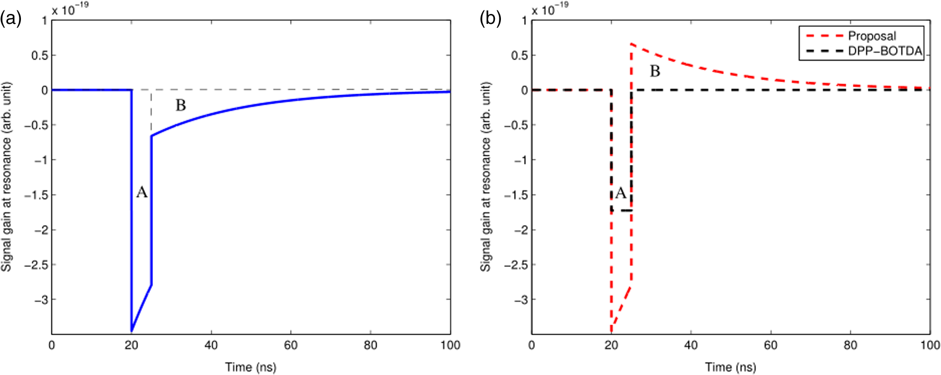 As illustrated by Eq. (9), the probe wave’s power in our technique will not change because Brillouin depletion or amplification of the probe wave occurs only when there is a temperature or strain change in the sensing fiber, while it changes in the -phase configuration according to a Lorenzian BGS as given by3 where is the peak value of the Brillouin gain at . As proven by Eq. (9), the Brillouin-induced contribution during the middle section is completely equal to the last section both in our proposed technique and the -phase configuration, which means the area of part A in Fig. 2 is equal to that of part B in Fig. 2. The only difference is that the resultant Brillouin gain is contributed by substraction of the two parts in our method, while it is contributed by summation in the traditional -phase pulse configuration. Hence, the BGS in our proposal is a differential BGS which can be experimentally validated in the following experimental part and it can be written aswhere the Brillouin resonance frequency of unperturbed segment is denoted as and that of perturbed segment is denoted as . As illustrated by Eq. (11), the BGS in the unperturbed segment will remain zero, which means the probe wave will not experience any Brillouin gain during the unperturbed segment. As a result, the photodetector in our proposal is less likely to become saturated and the power limitation of the probe wave can be alleviated.In order to validate such a Brillouin spectrum response, the general solutions given by Eqs. (7) and (8) are deployed to a standard SMF. The length of the fiber under simulation is set to 21.5 m with a fixed Brillouin resonance frequency of 10.873 GHz. A 50-cm long heated segment with a 36 MHz frequency shift (about 40°C for )14 is located approximately between 13.2 and 13.7 m. Further, is again assumed to be long enough to preactivate the acoustic field and the duration of the phase difference is given by 5 ns corresponding to 50-cm spatial resolution. Figure 3 is the contour color maps of the BGS with a frequency range of 17 GHz in steps of 2 MHz for our configuration and the -phase pulse configuration for comparison. Fig. 3Simulated top-view of the Brillouin signal with a Brillouin resonance frequency difference of 36 MHz between the perturbed segment and unperturbed segment: (a) our configuration and (b) -phase pulse configuration.  As depicted in Fig. 3, the top-view diagram of Brillouin gain in our system is considerably different from that in a conventional configuration. In our configuration, a differential BGS is presented and the heated segment with a resonance frequency difference of 36 MHz is clearly observed as shown in Fig. 3(a) where the stripes are caused by the last section of the pump wave when it passes through the heated segment. However, the BGS presents a classical Lorenzian spectrum with a nature Brillouin linewidth in -phase pulse configuration, and it can hardly detect a heated segment with a Brillouin resonance frequency difference of 36 MHz as shown in Fig. 3(b). That can be explained by the substraction as proven by Eq. (11) that yields a higher sensitivity to the variation of temperature or strain, especially when there is a small temperature or strain variation, which is difficult to achieve in a traditional distributed configuration. We also plot in Fig. 4 the probe signal traces at two typical pump-probe frequency differences both in our configuration and the -phase pulse configuration for further demonstration. As shown in Fig. 4(a), there exists much overlap between the two traces in our technique, which means that it is easier to capture small variations of temperature or strain, while, in case of Fig. 4(b), to accurately make a distinction between the unperturbed segment and the perturbed segment based on a Lorenzian BGS in a traditional distribution configuration becomes much more difficult. 3.Experimental Setup and ResultsThe validity of our technique was experimentally demonstrated with a 21.5-m long sensing fiber at a room temperature of 28°C with fixed Brillouin resonance frequency of 10.873 GHz for pump wavelength of 1550 nm. A 50-cm heated segment with a temperature of 68°C corresponding to about a 36 MHz frequency shift is loosely located at the same position as the above simulation part. The experimental setup was described in Fig. 5. A narrow linewidth () tunable laser with a 15.5-dBm output power working around 1550 nm was split into two parts as the probe and pump wave, respectively, by a 10:90 coupler. In the upper branch, the optical beam was directed to a Mach–Zehnder electrooptic modulator (MZ-EOM) driven by a microwave signal of about 11 GHz to generate a carrier-suppressed DSB wave. The two sidebands were then phase modulated by another MZ-EOM operating at a null transmission point to obtain a phase modulation. Then a commercial programmable optical filter (waveshaper 4000S) with a 3-dB filtering bandwidth of 10 GHz was employed to separate the anti-Stokes and Stokes sidebands. The anti-Stokes sideband was delayed by properly selecting the delay fiber ( corresponding to a 50 cm spatial resolution) and combined with a Stokes sideband with the same peak power and polarization by using a polarization controller (PC). Then they were amplified to 80 mW through an erbium-doped optical fiber amplifier (EDFA), were launched into the fiber under test and interacted with the probe wave by using an optical circulator. In the lower branch, the optical beam was first scrambled by a polarization scrambler (PS) to average the effect of the state of polarization (SOP) and was launched into the far end of the fiber with an optical power of 2 mW through an isolator. The probe wave was captured by a AC-coupled photodiode (PD) connecting to an oscilloscope with . Figure 6 depicts the contour color map of the Brillouin gain versus position and frequency shift captured by our proposed system, providing a preliminary demonstration of our sensing method’s validity. It clearly reveals that the 50-cm heated section can be easily recognized owing to the differential BGS as mentioned above. Additionally, the overlap of the probe signal traces obtained by experimental data as shown in Fig. 7 also demonstrate that the heated section can be easily captured by our technique. As a further demonstration of the performance of our proposal, we performed another analysis on precisely finding the Brillouin resonance frequency and by fitting the experimental data using Eq. (11). Fig. 6Three-dimensional (3-D) distribution of the Brillouin gain along the whole sensing fiber as a function of frequency and position: (a) the top-view diagram (b) the 3-D mappings diagram.  Fig. 7Probe signal traces of the real experimental result at three typical frequencies where the blue line is sloped mainly because of the unequivalent optical power of the two sideband pump waves during our experiment. 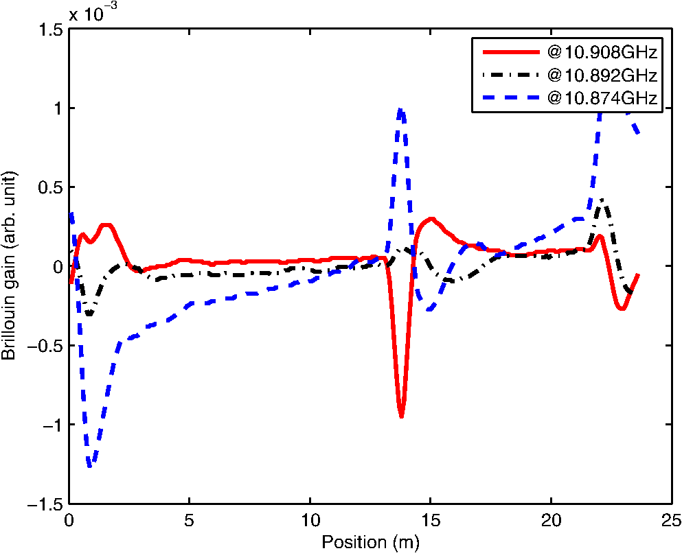 Figure 8(a) gives the measured BGS and fitting BGS using Eq. (11) at . A remarkable agreement between the measured data and fitting curve can be observed, which demonstrates that our fitting method based on Eq. (11) can achieve correct temperature information and the validation of Eq. (11) can also be experimentally illustrated at the same time. According to Eq. (11), we plot the differential BFS in Fig. 8(b), where the top view of the distribution information is measured in the vicinity of the 1-m fiber from 13.2 to 14.2 m. The effective 50-cm spatial resolution is further validated by the 10% to 90% response15 of the temperature step near the heated segment, which is determined by the 5-ns phase difference between the anti-Stokes and Stokes pump waves. The measured Brillouin frequency shift in the perturbed segment is 35.434 MHz as shown in Fig. 8(b), which indicates that the temperature change is about 40°C, coinciding with our experimental condition well. Fig. 8(a) Fitting Brillouin gain spectrum at and (b) distribution of Brillouin frequency shift along the whole sensing fiber fitted by Eq. (11). 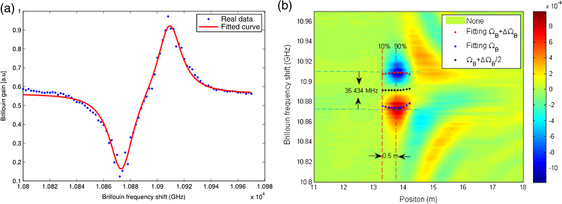 4.ConclusionIn conclusion, we have presented a novel scheme based on phase difference on a double-sideband pump wave and a 21.5-m sensing range with a 50-cm spatial resolution was theoretically simulated and experimentally demonstrated. In this paper, we have theoretically derived that only the differential part of the temperature or strain is detected without any extra measurement time, and the photodetector is less likely to become saturated, which means that the power of the probe wave can be increased in the case of a longer sensing range. Additionally, we have demonstrated that the SNR of our differential system is twice as high as that of DPP-BOTDA systems since a phase shift on the pump wave is implemented and a longer sensing range is possible to achieve. Further, the differential BGS also allows our proposal to a greater potential to recognize small variations of temperature or strain than the traditional Lorenzian BGS. Much better results could be achieved by pulsing the double-sideband pump wave in our experimental condition; this will require further investigation. AcknowledgmentsThis work was partly supported by 863 Program 2013AA014202, 973 Program 2014CB340100, NSFC Program 61307055, 61205031, 61331008, 61335009, 61307055, MOE Program 20130005110013, the Fundamental Research Funds for the Central Universities. ReferencesL. Thévenaz,
“Brillouin distributed time-domain sensing in optical fibers: state of the art and perspectives,”
Front. Optoelectron. China, 3 13
–21
(2010). http://dx.doi.org/10.1007/s12200-009-0086-9 1674-4128 Google Scholar
A. Fellay et al.,
“Distributed sensing using stimulated Brillouin scattering: towards ultimate resolution,”
in Proc. of 12th Int. Conf. on Optical Fiber Sensors,
324
–327
(1997). Google Scholar
G. Agrawal, Nonlinear Optics, Academic, New York
(2008). Google Scholar
J. C. Beugnot et al.,
“Distributed Brillouin sensing with sub-meter spatial resolution: modeling and processing,”
Opt. Express, 19
(8), 7381
–7397
(2011). http://dx.doi.org/10.1364/OE.19.007381 OPEXFF 1094-4087 Google Scholar
A. W. Brown, B. G. Colpitts and K. Brown,
“Dark-pulse Brillouin optical time-domain sensor with 20-mm spatial resolution,”
J. Lightwave Technol., 25
(1), 381
–386
(2007). http://dx.doi.org/10.1109/JLT.2006.886672 JLTEDG 0733-8724 Google Scholar
S. F. Mafang and M. Tur,
“High spatial and spectral resolution long-range sensing using Brillouin echoes,”
J. Lightwave Technol., 28
(20), 2993
–3003
(2010). http://dx.doi.org/10.1109/JLT.2010.2073443 JLTEDG 0733-8724 Google Scholar
T. Sperber et al.,
“High spatial resolution distributed sensing in optical fibers by Brillouin gain-profile tracing,”
Opt. Express., 18
(8), 8671
–8679
(2010). http://dx.doi.org/10.1364/OE.18.008671 OPEXFF 1094-4087 Google Scholar
Z. Yang et al.,
“Distributed Brillouin sensing with sub-meter spatial resolution based on four-section pulse,”
in Optical Fiber Communication Conf.,
(2013). Google Scholar
R. Bernini, A. Minardo and L. Zeni,
“Long-range distributed Brillouin fiber sensors by use of an unbalanced double sideband probe,”
Opt. Express, 19
(24), 23845
–23856
(2011). http://dx.doi.org/10.1364/OE.19.023845 OPEXFF 1094-4087 Google Scholar
Q. Cui et al.,
“Performance of double sideband modulated probe wave in BOTDA distributed fiber sensor,”
Microwave Opt. Technol. Lett., 52
(12), 2713
–2717
(2010). http://dx.doi.org/10.1002/mop.25566 MOTLEO 0895-2477 Google Scholar
W. Li et al.,
“Differential pulse-width pair BOTDA for high spatial resolution sensing,”
Opt. Commun., 16
(26), 21616
–21625
(2008). http://dx.doi.org/10.1364/OE.16.021616 OPCOB8 0030-4018 Google Scholar
Y. Li et al.,
“A novel distributed Brillouin sensor based on optical differential parametric amplification,”
J. Lightwave Technol., 28
(18), 2621
–2626
(2010). http://dx.doi.org/10.1109/JLT.2010.2057409 JLTEDG 0733-8724 Google Scholar
Z. Yang et al.,
“Stokes and anti-Stokes differential pulse pair based distributed Brillouin fiber sensor with double-sideband probe wave,”
Opt. Express, 22
(3), 2881
–2888
(2014). http://dx.doi.org/10.1364/OE.22.002881 OPEXFF 1094-4087 Google Scholar
T. Horiguchi et al.,
“Development of a distributed sensing technique using Brillouin scattering,”
J. Lightwave Technol., 13
(7), 1296
–1302
(1995). http://dx.doi.org/10.1109/50.400684 JLTEDG 0733-8724 Google Scholar
M. A. Soto et al.,
“Optimization of a DPP-BOTDA sensor with 25 cm spatial resolution over 60 km standard single-mode fiber using simplex codes and optical pre-amplification,”
Opt. Express, 20
(7), 6860
–6869
(2012). http://dx.doi.org/10.1364/OE.20.006860 OPEXFF 1094-4087 Google Scholar
BiographyWenqiao Lin received his MS degree in mathematics and applied mathematics from the Beijing University of Posts and Telecommunications (BUPT), Beijing, China, in 2013. Currently, he is working toward his PhD in electronic science and technology in the State Key Laboratory of Information Photonics and Optical Communications at BUPT. His current research interest is focused on the fiber-sensing system. Xiaobin Hong received his MSc degree in physics from Wuhan University, Wuhan, China, in 1997 and his PhD degree in optical communication from BUPT, Beijing, China. Currently, he is an assistant professor in BUPT. Before joining BUPT, he had worked in McMaster University, Hamilton, Ontario, Canada as a research fellow. His current research interests include fiber optic sensors, optical networks. |