

|
|
1.IntroductionLight beams in nonseparable superpositions of polarization and spatial mode encode modes with spatially variable polarization. These beams are also known as Poincaré beams because they carry a mapping of all states of polarization, as represented on the Poincaré sphere, onto the transverse mode of the beam.1 These beams are a general type of space-variant polarization modes of which cylindrical vector beams are a subset. Poincare beams have been generated by direct superposition in either free space1 or in optical fibers;2 or by passage through either a subwavelength diffractive optical element,3 a liquid-crystal birefringent optical element (so-called q-plate),4 or a stress-birefringent optical element.5 The use of these beams has enabled fundamental studies of polarization singularities,6,7 and in the encoding of quantum information onto single photons.8–11 The advantage of superposition methods stems from the freedom to encode any desired mode via electronic diffractive elements, such as spatial light modulators (SLM).12,13 Their shortcoming is in the alignment of the beams, which can be nontrivial; and in the stability of the patterns due to vibrations and air currents. In contrast, the use of a single optical element3–5 has the advantage of keeping the beams collinear, not requiring a lengthy optical alignment. Its shortcoming is the limitation in the number of modes that are available per optical element. To encode the most general Poincare beam, researchers must prepare a nonseparable state of polarization and spatial mode,1 where two spatial modes are prepared independently in orthogonal states of polarization. Thus, it necessitates a polarization interferometer design with a common path that uses SLM programming for both states of polarization. This type of encoding of SLMs has been accomplished previously by programming two halves of an SLM, where the amplitude-divided parts of the same beam are programmed separately by the same SLM to then be recombined cleverly by either a diffraction grating14 or a beam splitter in a double Sagnac interferometer.15 An alternative is to encode directly onto the orthogonal states of the same beam, such as with a double pass through a separate area of a transmissive SLM.16 In this article, we report on a common path design that uses two reflection-mode SLMs that are orthogonally oriented. It is similar to previous designs that used two consecutive SLMs for image encryption, one to encode patterns and the other to decode them.17,18 In our design, described in detail in Sec. 2, the two SLMs encode the superposition of any two modes in orthogonal states of polarization. The design is simple and robust, producing collinear superpositions with ease. It leaves the more difficult tasks to the encoding of the SLMs, which are driven by a straightforward connection to a computer. In this article, we demonstrate the operation of this arrangement by presenting two types of Poincaré beams that have not been reported previously. They involve two types of space-variant polarization patterns. The first one involves the generation of beams with concentric polarization-singularity C-points.19 In particular, we show lemon and star polarization singularity patterns using high-order spatial modes. Previous work was limited to first-order modes.1,2,6 The versatility of the SLM allows the extension of previous studies with ease. In Sec. 3, we present the theory of these Poincaré modes followed by the corresponding measurements. 2.ApparatusThe preparation of collinear light beams with an arbitrary nonseparable superposition of spatial modes and polarization necessitates an interferometer type of device that uses the versatility of SLMs to encode the desired spatial modes onto orthogonal states of polarization. As aforementioned, the conventional interferometer poses an alignment challenge for achieving collinearity. Here we describe an experimental design with two SLMs that uses a same-path interferometer, which guarantees collinearity. The design is shown in Fig. 1. It exploits the polarization selectivity of SLMs: they shift the phase of the field component that is parallel to the axis of the SLM. Fig. 1Schematic of the apparatus. Optical elements include lenses (L), half-wave plates (H), quarter-wave plates (Q), polarizer (P), neutral density filter (F), single-mode fiber (SF), fiber collimator (C), spatial light modulators (SLM), and digital camera (DC). The SLMs were rotated by 90 deg relative to each other.  The initial beam of light was generated by a 3 mW diode laser oscillating at 694 nm. It was coupled to a single-mode fiber and sent into free space via a fiber collimator. This ensured that the input beam was in a pure Gaussian mode. The light was further refocused to make the wavefront as planar as possible. The beam was also prepared in a linearly polarized state forming an angle with respect to the horizontal. Upon reaching the first SLM, one polarization component (vertical, and parallel to the axis of the SLM) was encoded with the spatial mode . The SLM, mounted on an XY stage, was operated in reflection mode (as opposed to diffraction mode20). This way, the spatial mode associated with the orthogonal polarization (horizontal) was not affected by the SLM but continued traveling along the same path as the other component. Past refocusing 4-f optics and a relaying mirror (not shown), the light encountered a second SLM similar to the first one but with its axis rotated by 90 deg. This SLM encoded in reflection mode a second spatial mode onto the horizontal polarization component, leaving the vertical component unaffected. Optical elements past the second SLM performed a unitary operation that put the light in a desired polarization basis. In the case of Fig. 1, we used a quarter-wave plate, with fast axis at with respect to the horizontal, to put the modal superposition in the circular polarization basis. The mode that was constructed was then where and are complex constants, and and denote the states of right and left circular polarizations, respectively. The relative magnitude of and was adjusted by the initial half-wave plate that determined the orientation of the input polarization. The relative phase between the modes was encoded onto the SLM patterns that were programmed.We used commercial SLMs from Boulder Nonlinear Inc., model P512, with dimensions. We did a general custom calibration of the overall phase of the SLM pixels for our working wavelength.21 In this work, we concentrated on superpositions that involved the circular basis. However, with a suitable unitary transformation after the second SLM, we could transform the linear basis to any other polarization basis. This in turn gives rise to distinct types of polarization-singularity patterns. In a previous study, we showed that the rectangular linear basis gives rise to symmetric multipole distributions of C-points, and elliptical bases give rise to asymmetric multipole distributions.1 We mentioned that we can change the relative phase between the two terms of the superposition via the encoding of the SLMs. However, that is not a restriction. One can easily use an alternative means to introduce a specific relative phase: a Pancharatnam–Berry phase shifter.22 This type of device, the most simple of which consists of three wave plates, inserts a geometric phase between the orthogonal polarization components, with the value of the phase specified by the orientation of one of the wave plates. Alternatively, one can use a birefringent plate, tilting it to adjust the relative phase. We diagnosed the state of the light by imaging polarimetry with a digital camera.23 This entailed taking images with six distinct polarization filters: linear-horizontal (H), linear-vertical (V), linear-diagonal (D, ), linear-antidiagonal (A, ), right-circular (R), and left-circular (L).24 The six images were then postprocessed to obtain the Stokes parameters of each imaged point:25 , , , and , where 's are the recorded intensities after filter . Our detection scheme is shown in Fig. 1. The polarization filter consists of a series of four optical elements: a half-wave plate (variable), a quarter-wave plate (fixed with fast axis horizontal), a half-wave plate (variable), and a Glan–Thompson polarizer (fixed with transmission axis horizontal). This scheme gave us the flexibility to diagnose the Poincaré beams easily, because the first and second half-wave plates controlled, respectively, the ellipticity and orientation of the transmission polarization eigenstate of the filter.1 With the Stokes parameters obtained from the filtered images, we were able to fully determine the state of polarization of each imaged point. The patterns that were obtained indeed exhibited a very good degree of collinearity. In the remainder of the article, we will focus on two important cases of Poincaré beams that were easily achievable with this setup. 3.Theory and Comparisons with MeasurementsThis work follows previous research by us on two independent problems involving the creation of beams with composite vortices26,27 and polarization singularities.1,7,28 Here we focus on a general case that encompasses both. It involves beams in a general superposition mode given by where , , , and are parameters that we can vary; and is a Laguerre–Gauss spatial mode with zero radial index (i.e., with singly ringed “doughnut” transverse amplitude) and topological charge . The spatial mode is given by where and are the transverse polar coordinates; , the amplitude of the mode, is given by with being the half-width of the mode; is the Gaussian function, given by and is a phase term, given by where is the wave vector, is the radius of curvature of the wavefront, and is the Gouy phase, given by where is the Rayleigh range.3.1.C-PointsIf we make yet , we have the superposition of two spatial Laguerre–Gauss modes in orthogonal polarization states. In general, this gives rise to Poincaré modes with a C-point at their center. C-points are singular points of ellipse orientation (i.e., direction of the semimajor axis). In following a counterclockwise closed path around the C-point, the orientation of the ellipses rotates either clockwise or counterclockwise. This rotation is described by the C-point singularity index.19 The orientation of the ellipses in lemon (star) C-points completes a half-turn counterclockwise (clockwise) per closed counterclockwise path around the C-point. Consequently, for lemon and star patterns, is and , respectively. The orientation of an ellipse is half of the relative phase between the right and left circular polarization components. If we encode modes with topological charges and with right and left circular polarizations, respectively, then the orientation is given by where is an integer, is the phase between the two polarization components, and . We call the polarization pattern symmetric because of the linear relation between and . Since and have fixed values for a given beam, the singularity index isTherefore, when and , the patterns that are formed are symmetric lemons and stars, respectively. The different cases denoted by the individual values of and have distinct distributions of ellipticity. The ellipticity is determined by the ratio of the amplitudes between the two circular polarization components, which in turn is due to the spatial distribution of amplitudes of the individual modes. Thus, or specify a class of patterns that have respectively the same lemon or star symmetric line singularity structure in the orientation of the semimajor axes of the ellipses, irrespective of the individual values of and . For and , the ellipses have radial orientations at all the angles. This is the radial mode, popularized by the case , and known as the radial vector beam.29 In this case, all the states of polarization are linear. For , the semimajor axes are radial, but the states are elliptical, with the ellipticity depending on the radial coordinate. When , there are no radial orientations. The case is also known as the tangential mode because all the semimajor axes are tangential to circles centered at the singular point. When is neither 0 nor , the mode describes a swirl-type pattern. Figure 2 shows examples of these three cases, displaying the predicted patterns and the measured ones. Fig. 2Simulations (top row) and measurements (bottom row) of three types of Poincaré beams. Referring to Eq. (2), (a) and (b) correspond, respectively, to symmetric lemon (with and ) and star (with and ) C-point polarization patterns. (c) Corresponds to a mode that does not contain a C-point. When the phase difference between modes is not 0 or , and the semimajor axes of the polarization ellipses form a swirl, (c) corresponds to .  The measured patterns of ellipses in Fig. 2 follow the simulated ones: lemon C-point for Fig. 2(a), star C-point for Fig. 2(b), and swirl for Fig. 2(c). The simulations are simple superpositions of modes, per Eq. (2), and do not account for beam propagation effects. It is clear that points along radial lines in the measurements do not all have the same orientations (encoded by the false color) as in the simulations. The curvature in the color boundaries in the measurements illustrates this. We attribute the discrepancy to the different wavefront curvatures of the two modes. This may be corrected by feeding back phase corrections to the two SLMs. The patterns still demonstrate the general expectation: the production of space-variant polarization following a particular singularity pattern. The measurements and simulations agree well in the neighborhood of the central singular point. In summary, the superposition of two orthogonally polarized modes with one or both carrying an optical vortex (of different topological charge) creates a C-point pattern. Here we concentrated on cases with . Cases with (but not ) give rise to modes carrying high-order C-point singularities, also known as hyper C-points.19 Hyper lemons contain patterns also known as flowers, which are characterized by their petals; and hyper stars contain patterns also known as hyperbolic webs, which are characterized by multiple star-points.30 Our work on these cases is ongoing and will be reported elsewhere. 3.2.Composite C-PointsThe case when but in Eq. (2) is one where the total mode has the same state of polarization, rendering polarization irrelevant to the physics of the problem. Variables and specify the degree to which the two spatial modes bearing optical vortices combine. This type of superposition yields a beam with composite vortices:26,27 for , they consist of a central vortex of topological charge surrounded by singly charged vortices, of charge symmetrically distributed about the center at angles with , and at a radial distance obtained by equating the amplitudes of the two spatial modes [within the parentheses in Eq. (2)].27When , we get a superposition of composite vortices in one state of polarization with another mode that may or may not have vortices (in the orthogonal state of polarization), giving rise to composite C-points. Figure 3 gives a few examples. With one SLM, we can generate the mode pattern of composite optical vortices by encoding the superposition onto the SLM. The parameter that determines the number and sign of vortices is . The radial distribution of ellipses depends on the individual values of and , per Eq. (12). The angular distribution depends on the relative phase between modes 1 and 3, per Eq. (11). All three cases of Fig. 3 correspond to , giving rise to three lemon C-points forming a symmetrical triangular pattern located about the center of the beam. In Figs. 3(a) and 3(c), and . The composite vortices that they carry entail three peripheral vortices of topological charge and a central vortex () of topological charge . Figure 3(b) has and , which also yields three peripheral vortices of topological charge and a central vortex of topological charge . The mode encoded by the other SLM may or may not encode an optical vortex. In Figs. 3(a) and 3(b), we set , which entails no central vortex, but for Fig. 3(c), we set , which entails a central vortex of topological charge . Fig. 3Simulations (top row) and measurements (bottom row) of cases of composite C-point patterns. Following Eq. (2), they correspond to cases where and . They produce patterns that are similar but with subtle distinctions (see text). They correspond to , , and for (a); , , and for (b), and , , and for (c). The phases for the simulations were set to match the measurements. They are (in degrees) (80, 210) for (a), (20, 160) for (b), and (80, 110) for (c). False color represents ellipse orientation, and saturation is related to the intensity of the beam. 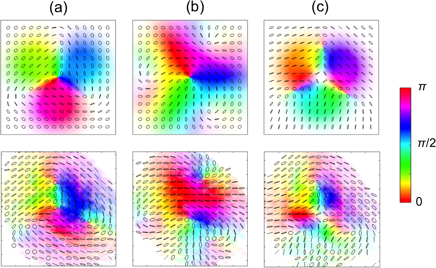 The superposition of the two modes with orthogonal polarization preserves the location of the vortices of each mode, giving rise to C-points where there are vortices in each component. However, the orientation of the ellipses in the patterns depends on the relative phase distribution between the modes. Thus, all three cases give rise to a central C-point, which has an index : for Fig. 3(a), for Fig. 3(b), and for Fig. 3(c). Since a vortex in one polarization is combined with a nonuniform phase with the other polarization, the result is that most, if not all, C-points are asymmetric, and with a subset of positive index C-points being monstars.7 The first row of panels in Fig. 3 shows simulations with phases and set to match the experimental results, which are shown in the second row. These phases differ for each case. They are mostly due to Gouy phases accumulated as the beams traveled through the lenses in our apparatus, but may include phases introduced by the SLMs. As aforementioned, the color in the panels encodes the orientation of the ellipses. This false color helps in recognizing the pattern of ellipses and in comparing the measurements with the simulations. There is good qualitative agreement between measurements and simulations on the type of C-point patterns, the location of the C-points, and the general orientation of the ellipses around them. It is clear that the ellipse orientations follow the general pattern that is predicted, including the false color. They disagree in some of the details, such as the uniformity as a function of the distance from the C-points and intensity distributions. Some of these may be caused by passage through inhomogeneous optical elements, which may insert geometrical aberrations. They may also be due to limitations in the phase encoded by the SLM. Since the SLMs are phase only, they do not produce perfect spatial modes upon reflection. We introduced additional phases to the patterns to modulate the amplitude of the modes, by diffracting out some of the light. We did not correct for this completely, and as a consequence, the modes were not pure. These and other phase imperfections can be further corrected by introducing feedback in the programming of the SLMs. The data shown in Fig. 3 are representative of a larger study that we did, where we took data on a number of other combinations of topological charges with distinct amplitudes and phases. They all show the same level of agreement between the measurements and simulations. We only showed cases where one composite mode was combined to another eigenmode, per Eq. (2), but the latter could, in principle, be another composite mode, in which case the vortices of each mode will produce C-points in the resulting mode. The apparatus is well-suited for the preparation and study of asymmetric C-points, including monstars, a type of C-point with characteristics of both lemons and stars.31,32 The asymmetric cases that we studied previously7 involved , , and in Eq. (2), which result in the production of an asymmetric optical vortex in one of the polarization components,27 giving rise to asymmetric C-points and monstars.7 However, the cases with give rise to a larger variety of asymmetric C-points and hyper C-points that have not been studied previously, which are accessible with the apparatus presented here. 4.Discussion and ConclusionsIn summary, we presented an experimental design for encoding Poincaré beams using two reflection-mode SLMs in a same-path polarization interferometer. The setup is robust against common dephasing mechanisms, such as vibrations and air currents. The quality of the beams that we obtained can be further improved by using feedback in the encoding of the SLMs. In this study, we imaged the beams in the far-field. Through their propagation, the beams acquired Gouy phases, which rotated the composite mode of one polarization component,27,33 and also rotated the polarization ellipses in the final space-variant mode.6 All of these relative phases could be changed by modifying the patterns programmed onto the SLMs. If the beams propagate further through an additional optical system, the patterns will inevitably change due to the new propagation phases. We used our experimental arrangement to obtain new results on the encoding of polarization singularities with Poincaré beams. We generated new types of symmetric lemon and star C-point patterns by encoding high-order optical vortices onto the orthogonal polarization components. We also presented new results on the preparation of beams with noncentral C-points, which we call composite C-points. They show how we can encode C-points in any location of the transverse profile of the beam via a suitable superposition of spatial modes and their relative phases and amplitudes. There is good agreement between the measurements and expectations. These are also new results not reported previously. The setup can also be used to examine other types of situations, such as displaced modes,34,35 noncollinear modes,36 three-dimensional Möbius patterns,37,38 and new forms of knotted light39 that include polarization. These can be accomplished by using birefringent optical elements or by inserting additional phases to the pattern programmed onto the SLM. The present work only considered coherent beams, but the apparatus can be modified for investigating the patterns of partially polarized beams.40,41 By inserting birefringent crystals anywhere in the path of the light, we can delay one polarization component relative to the other by amounts comparable to the coherence time of the beam of light. The apparatus can also be used to access a larger multidimensional space of polarization and spatial modes of single photons.11,42 In the present study, we initiated a new regime of fundamental studies of polarization singularities via a simple and flexible apparatus. The classical beams have intriguing space-variant patterns encoding singularities that are yet to be fully uncovered. Since C-points encode polarization, as opposed to optical vortices, which encode phase, they are more amenable for the encoding of information because these can be easily decoded via imaging polarimetry. In combination with imaging systems that decode polarization,43 this system can be used for adding polarization to encoding and sensing of imaging information. AcknowledgmentsB.K. thanks W. Miller for encouragement and support. This work received financial support from Florida Atlantic University and Colgate University. The equipment was provided by U.S. Air Force contract FA8750-11-2-0034. ReferencesE. Galvez et al.,
“Poincaré-beam patterns produced by non-separable superpositions of Laguerre-Gauss and polarization modes of light,”
Appl. Opt., 51 2925
–2934
(2012). http://dx.doi.org/10.1364/AO.51.002925 APOPAI 0003-6935 Google Scholar
N. Viswanathan and V. Inavalli,
“Generation of optical vector beams using a two-mode fiber,”
Opt. Lett., 34 1189
–1191
(2009). http://dx.doi.org/10.1364/OL.34.001189 OPLEDP 0146-9592 Google Scholar
A. Niv et al.,
“Rotating vectorial vortices produced by space-variant sub wavelength gratings,”
Opt. Lett., 30 2933
–2935
(2005). http://dx.doi.org/10.1364/OL.30.002933 OPLEDP 0146-9592 Google Scholar
L. Marrucci, C. Manzo and D. Paparo,
“Optical spin-to-orbital angular momentum conversion in inhomogeneous anisotropic media,”
Phys. Rev. Lett., 96 163905
(2006). http://dx.doi.org/10.1103/PhysRevLett.96.163905 PRLTAO 0031-9007 Google Scholar
A. Beckley, T. Brown and M. Alonso,
“Full Poincaré beams,”
Opt. Express, 18 10777
–10785
(2010). http://dx.doi.org/10.1364/OE.18.010777 OPEXFF 1094-4087 Google Scholar
F. Cardano et al.,
“Generation and dynamics of optical beams with polarization singularities,”
Opt. Express, 21 8815
–8820
(2013). http://dx.doi.org/10.1364/OE.21.008815 OPEXFF 1094-4087 Google Scholar
E. Galvez et al.,
“Generation of isolated asymmetric umbilics in light’s polarization,”
Phys. Rev. A, 89 031801
(2014). http://dx.doi.org/10.1103/PhysRevA.89.031801 Google Scholar
J. Barreiro, T.-C. Wei and P. Kwiat,
“Remote preparation of single-photon ‘hybrid’ entangled and vector-polarization states,”
Phys. Rev. Lett., 105 030407
(2010). http://dx.doi.org/10.1103/PhysRevLett.105.030407 PRLTAO 0031-9007 Google Scholar
E. Nagali et al.,
“Quantum information transfer from spin to orbital angular momentum of photons,”
Phys. Rev. Lett., 103 013601
(2009). http://dx.doi.org/10.1103/PhysRevLett.103.013601 PRLTAO 0031-9007 Google Scholar
H. Kagalwala et al.,
“Bell’s measure in classical optical coherence,”
Nat. Photonics, 7 72
–78
(2013). http://dx.doi.org/10.1038/nphoton.2012.312 NPAHBY 1749-4885 Google Scholar
R. Fickler et al.,
“Quantum entanglement of complex photon polarization patterns in vector beams,”
Phys. Rev. A, 89 060301
(2014). http://dx.doi.org/10.1103/PhysRevA.89.060301 Google Scholar
C. Maurer et al.,
“Tailoring of arbitrary optical vector beams,”
New J. Phys., 9 78
(2007). http://dx.doi.org/10.1088/1367-2630/9/3/078 NJOPFM 1367-2630 Google Scholar
D. Preece et al.,
“Independent polarization control of multiple optical traps,”
Opt. Express, 16 15897
–15902
(2008). http://dx.doi.org/10.1364/OE.16.015897 OPEXFF 1094-4087 Google Scholar
X.-L. Wang et al.,
“Generation of arbitrary vector beams with a spatial light modulator and a common path interferometric arrangement,”
Opt. Lett., 32 3549
–3551
(2007). http://dx.doi.org/10.1364/OL.32.003549 OPLEDP 0146-9592 Google Scholar
R. Fickler et al.,
“Quantum entanglement of high angular momenta,”
Science, 338 640
–643
(2012). http://dx.doi.org/10.1126/science.1227193 SCIEAS 0036-8075 Google Scholar
I. Moreno et al.,
“Complete polarization control of light from a liquid crystal spatial light modulator,”
Opt. Express, 20 364
–376
(2012). http://dx.doi.org/10.1364/OE.20.000364 OPEXFF 1094-4087 Google Scholar
P. Mogensen and J. Glückstad,
“A phase-based optical encryption system with polarization encoding,”
Opt. Commun., 173 177
–183
(2000). http://dx.doi.org/10.1016/S0030-4018(99)00633-1 OPCOB8 0030-4018 Google Scholar
J. Davis, G. Evans and I. Moreno,
“Polarization-multiplexed diffractive optical elements with liquid-crystal displays,”
Appl. Opt., 44 4049
–4042
(2005). http://dx.doi.org/10.1364/AO.44.004049 APOPAI 0003-6935 Google Scholar
I. Freund,
“Polarization singularity indices in Gaussian laser beams,”
Opt. Commun., 201 251
–270
(2002). http://dx.doi.org/10.1016/S0030-4018(01)01725-4 OPCOB8 0030-4018 Google Scholar
L. Leach, E. Yao and M. Padgett,
“Observation of the vortex structure of a non-integer vortex beam,”
New J. Phys., 6 71
(2004). http://dx.doi.org/10.1088/1367-2630/6/1/071 NJOPFM 1367-2630 Google Scholar
J. Otón et al.,
“Multipoint phase calibration for improved compensation of inherent wavefront distortion in parallel aligned liquid crystal on silicon displays,”
Appl. Opt., 46 5667
–5679
(2007). http://dx.doi.org/10.1364/AO.46.005667 APOPAI 0003-6935 Google Scholar
E. Galvez,
“Applications of geometric phase in optics,”
Recent Research Developments in Optics, 2 165
–182 Research Signpost, Kerala
(2002). Google Scholar
E. Galvez, B. Rojec and K. Beach,
“Mapping of all polarization-singularity C-point morphologies,”
Proc. SPIE, 8999 89990I
(2014). http://dx.doi.org/10.1117/12.2038947 PSISDG 0277-786X Google Scholar
I. Freund, M. Soskin and A. Mokhun,
“Elliptic critical points in paraxial optical fields,”
Opt. Commun., 208 223
–253
(2002). http://dx.doi.org/10.1016/S0030-4018(02)01585-7 OPCOB8 0030-4018 Google Scholar
H. Berry, G. Gabrielse and A. Livingston,
“Measurement of the Stokes parameters of light,”
Appl. Opt., 16 3200
–3205
(1977). http://dx.doi.org/10.1364/AO.16.003200 APOPAI 0003-6935 Google Scholar
E. Galvez, N. Smiley and N. Fernandes,
“Composite optical vortices formed by collinear Laguerre-Gauss beams,”
Proc. SPIE, 6131 613105
(2006). http://dx.doi.org/10.1117/12.646074 PSISDG 0277-786X Google Scholar
S. Baumann et al.,
“Propagation dynamics of optical vortices due to Gouy phase,”
Opt. Express, 17 9818
–9827
(2009). http://dx.doi.org/10.1364/OE.17.009818 OPEXFF 1094-4087 Google Scholar
E. Galvez and S. Khadka,
“Poincaré modes of light,”
Proc. SPIE, 8274 82740Y
(2012). http://dx.doi.org/10.1117/12.909469 PSISDG 0277-786X Google Scholar
Q. Zhan,
“Cylindrical vector beams: from mathematical concepts to applications,”
Adv. Opt. Photonics, 1 1
–57
(2009). http://dx.doi.org/10.1364/AOP.1.000001 AOPAC7 1943-8206 Google Scholar
I. Freund,
“Polarization flowers,”
Opt. Commun., 199 47
–63
(2001). http://dx.doi.org/10.1016/S0030-4018(01)01533-4 OPCOB8 0030-4018 Google Scholar
M. Berry and J. Hannay,
“Umbilic points on Gaussian random surfaces,”
J. Phys. A Math. Gen., 10 1809
–1821
(1977). http://dx.doi.org/10.1088/0305-4470/10/11/009 Google Scholar
M. Dennis,
“Polarization singularities in paraxial vector fields: morphology and statistics,”
Opt. Commun., 213 201
–221
(2002). http://dx.doi.org/10.1016/S0030-4018(02)02088-6 OPCOB8 0030-4018 Google Scholar
Y. Schechner, R. Piestun and J. Shamir,
“Wave propagation with rotating intensity distributions,”
Phys. Rev. E, 54 R50
–R53
(1996). http://dx.doi.org/10.1103/PhysRevE.54.R50 Google Scholar
I. D. Maleev and G. A. SwartzlanderJr.,
“Composite optical vortices,”
J. Opt. Soc. Am. B, 20 1169
–1176
(2003). http://dx.doi.org/10.1364/JOSAB.20.001169 JOBPDE 0740-3224 Google Scholar
D. Kalb and E. Galvez,
“Composite vortices of displaced Laguerre-Gauss beams,”
Proc. SPIE, 7227 72270B
(2009). http://dx.doi.org/10.1117/12.808814 PSISDG 0277-786X Google Scholar
E. Galvez et al.,
“Space-variant polarization patterns of non-collinear Poincaré superpositions,”
Proc. SPIE, 9379 93790G
(2015). http://dx.doi.org/10.1117/12.2079058 PSISDG 0277-786X Google Scholar
I. Freund,
“Möbius strips and twisted ribbons in intersecting Gauss Laguerre beams,”
Opt. Commun., 284 3816
–3845
(2011). http://dx.doi.org/10.1016/j.optcom.2011.04.032 OPCOB8 0030-4018 Google Scholar
T. Bauer et al.,
“Observation of optical polarization Möbius strips,”
Science, 347 964
–966
(2015). http://dx.doi.org/10.1126/science.1260635 SCIEAS 0036-8075 Google Scholar
L. Leach, E. Yao and M. Padgett,
“Vortex knots in light,”
New J. Phys., 7 55
(2005). http://dx.doi.org/10.1088/1367-2630/7/1/055 NJOPFM 1367-2630 Google Scholar
C. Felde et al.,
“Polarization singularities in partially coherent combined beams,”
JETP Lett., 88 418
–422
(2008). http://dx.doi.org/10.1134/S002136400819003X JTPLA2 0021-3640 Google Scholar
A. Beckley, T. Brown and M. Alonso,
“Full Poincaré beams II: partial polarization,”
Opt. Express, 20 9357
–9362
(2012). http://dx.doi.org/10.1364/OE.20.009357 OPEXFF 1094-4087 Google Scholar
B. Khajavi et al.,
“Encoding and decoding non-separable states of polarization and spatial mode of single photons,”
Proc. SPIE, 9379 93790A
(2015). http://dx.doi.org/10.1117/12.2079038 PSISDG 0277-786X Google Scholar
D. Miller and E. Dereniak,
“Selective polarization imager for contrast enhancements in remote scattering media,”
Appl. Opt., 51 4092
–4102
(2012). APOPAI 0003-6935 Google Scholar
BiographyBehzad Khajavi is a PhD student in the Department of Physics and Astronomy at Florida Atlantic University and is working collaboratively on this project at Colgate University. He received his BS degree in physics from Bu-Ali Sina University, Iran, in 2006, his MS degree in elementary particle physics from Isfahan University of Technology, Iran, in 2009, and his MS degree in physics education from Florida Atlantic University in 2013. Enrique J. Galvez is the Charles A. Dana professor of physics and astronomy at Colgate University. He received his BS degree in physics at the Pontifical Catholic University of Peru in 1980. He received his PhD degree in atomic physics at the University of Notre Dame in 1986. He has been at Colgate University since 1988 after a postdoctoral appointment at Stony Brook University. His research interests include atomic and optical physics and physics education. He is member of SPIE and has been chair and cochair of the conference series on Complex Light and Optical Forces. |


