|
|
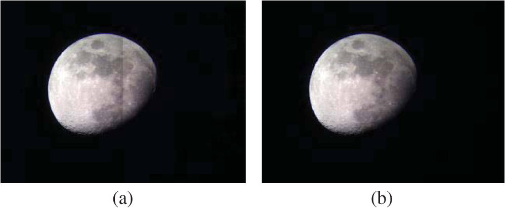
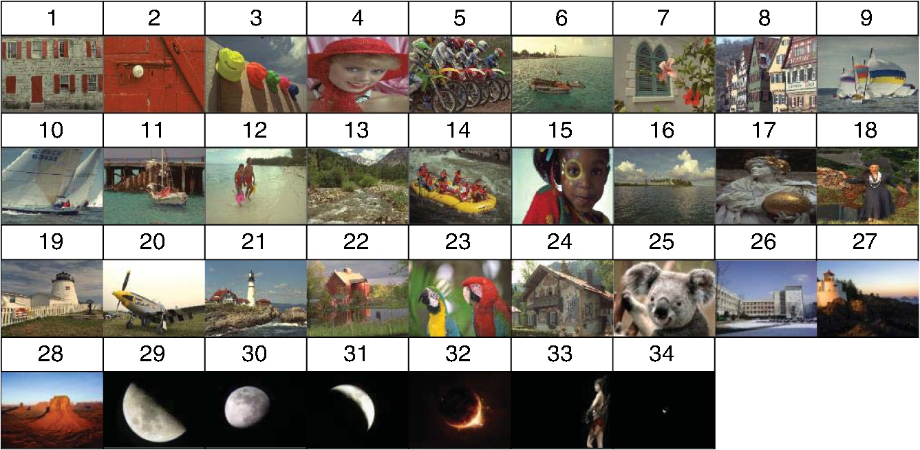
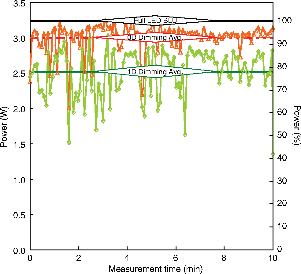
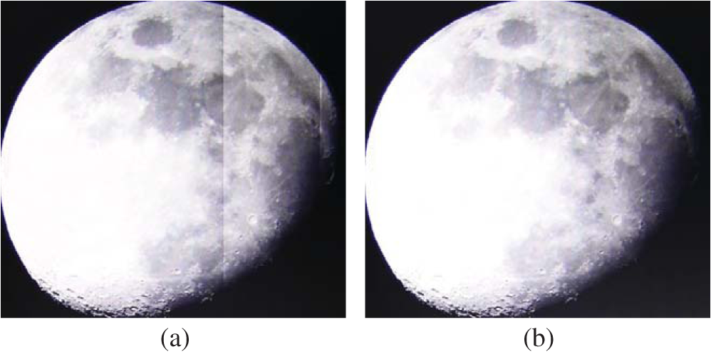
1.IntroductionRecently, the increased power consumption of liquid crystal displays (LCDs) has become a concern.1–6 To reduce power consumption while increasing image quality in LCDs, various technologies have been studied such as backlight dimming,7–15 inversion methods,16–18 and charge sharing methods.19–24 Based on a demand for slim designs and low power consumption, a side-lit light-emitting diode (LED) backlight unit (BLU) has been widely adopted not only in mobile LCD applications but also in large LCDs.9–14 To further reduce power consumption in LCDs, a dimming technique was developed. Dimming techniques can be generally categorized as three types: zero-dimensional (0-D), one-dimensional (1-D), or two-dimensional (2-D) dimming techniques. The 0-D dimming technique has been widely used in various devices, such as mobile devices and LCD televisions (TVs), because of low cost and simple implementation. For higher image quality and higher power savings, the 2-D dimming technique also has been adopted for large-sized LCDs. With a demand for slimmer design and lower power driving, a side-lit LED BLU has been widely adopted not only in mobile devices but also in large-sized LCDs. For this reason, the 1-D dimming technique has been widely studied. Conventional dimming techniques compensate for the luminance of each LED unit depending on the contents of the image block. Thus, the luminance of the image block area is considered to be uniform.25–29 However, the luminance gradually varies across the image block depending on the distance from each LED unit. Thus, the luminance of an image block may not be uniform throughout the block when some LED units are on and others are off. This phenomenon often causes the boundaries between image blocks to be visible.10 In this report, we approximate the distribution with polynomial expressions based on measurements and propose a new algorithm that can be implemented easily in hardware. In addition, we demonstrate how the block artifact is eliminated, how the image quality improves, and how much power consumption is reduced. In this paper, we propose an adaptive 1-D dimming technique for reducing the power consumption and increasing the image quality of LCDs. Through the analysis of input image data and BLU luminance distribution, our proposed 1-D dimming technique selectively dims LEDs only when the compensated image guarantees a net power benefit and higher image quality. In Sec. 2, we propose the basic principle of the adaptive 1-D dimming technique. In Sec. 3, we present the experimental results. Finally, Sec. 4 provides a summary and conclusion. 2.Distribution of Side-Lit Light-Emitting Diode Backlight Unit and Pixel CompensationAn adaptive dimming technique dims a BLU according to input image data. In this paper, we assume that LEDs are placed at the lower edge of the LCD panel and are divided into eight units. Figure 1 shows the schematic image of luminance distribution for dimmed LED units over an LCD panel with a side-lit LED BLU. Fig. 1Schematic diagrams of (a) ideal and (b) actual luminance distributions of side-lit light-emitting diode (LED) backlight when four LED units are turned on. 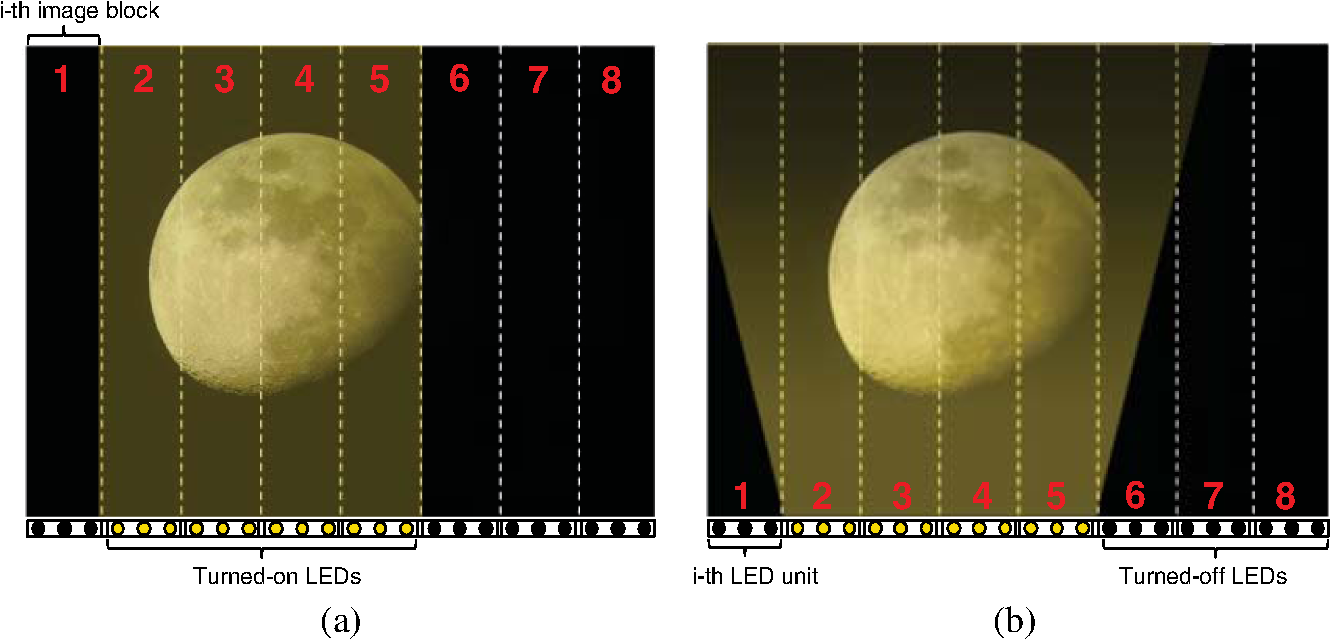 In Fig. 1, a sample image is divided into eight blocks (’th image block, to 8). Moreover, LEDs are divided into eight regions (’th LED unit, to 8). Figure 1(a) shows the ideal luminance distribution of four turned-on LED units while the other four are off. However, we found that the actual luminance distribution appears as shown in Fig. 1(b). A severe visual artifact, such as a block artifact, may be unavoidable if the ideal luminance distribution of the turned-on LED units is used. To eliminate this problem, we need to determine the actual luminance distribution over the entire panel. Figure 2(a) shows the measured luminance distribution of one LED unit. We measured the luminance data of the panel along the - and - directions using a BLU module inspection system, BLU-1000. To represent the backlight distribution in a compensation algorithm, we approximated the luminance distribution of the ’th LED unit by two simple polynomial expressions for the - and -directions:9 where and are the luminance distributions of the ’th LED unit in the - and -directions, respectively; and range from 1 to 1024 and from 1 to 768, respectively; is the location of the ’th LED unit ranging from 1 to 1024; is the entire luminance distribution of the ’th LED unit obtained from Eq. (1) and (2); and , the actual luminance at location , is the sum of luminance contributions by eight LED units as in Eq. (4): Using these equations, we modeled the luminance distribution of one LED block unit based on the Eqs. (1)–(3), as shown in Fig. 2(b). where , divided into 256 levels from 0 to 255, is the backlight level of the ’th LED unit that is determined by our proposed Eq. (5); and are, respectively, the maximum and average values of the input image corresponding to the ’th image block; and is an adjusting value. When the average value of the ’th block is higher than the average value of the entire image, it means that the highlight such as star light is mainly located in the ’th block. To maintain the image quality, the adjusting value is adjusted to . When the average value of the ’th block is lower than the average value of the entire image, it means that the highlight is not mainly located in the ’th block. To reduce the power consumption, the adjusting value is adjusted to . To maintain the same luminance after dimming the backlight, is introduced and calculated using Eq. (6).7 is an image data level that ranges from 0 to 255. and are the image data and BLU level, respectively, when the backlight is fully turned on.Fig. 2(a) Measured luminance distribution of one LED unit and (b) the luminance distribution model of one LED block unit. 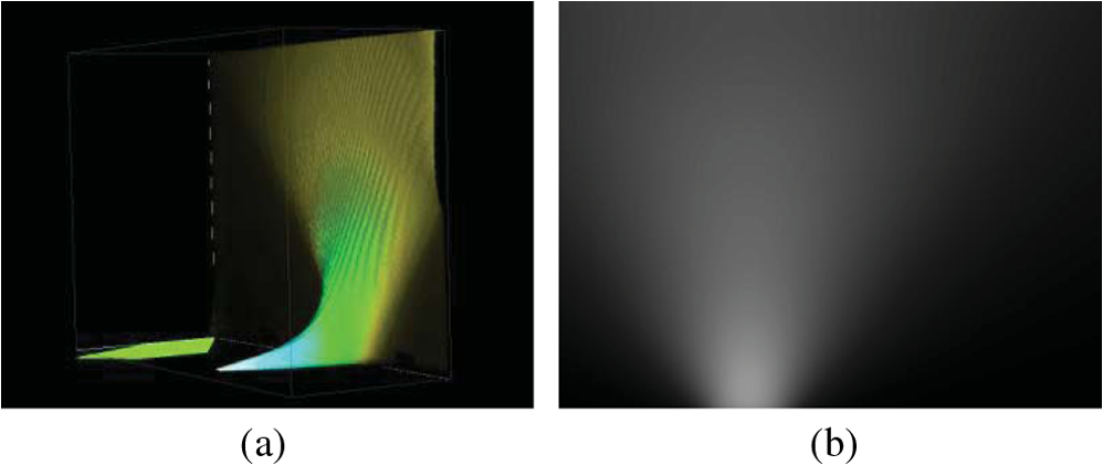 Conventional methods compensate for the dimmed luminance by increasing image data as in Eq. (6) without considering the nonuniform luminance distribution of the BLU.7 If pixels are compensated based on Eq. (6), severe block artifacts may be caused because does not fully reflect the luminance distribution over the screen. Therefore, we suggest a novel pixel compensation as follows: 3.Experimental Results3.1.Simulation ResultIn order to verify the elimination of the block artifact, we simulated a 1-D dimming technique with nonuniform luminance distribution and measured the luminance distribution using MATLAB. Figure 3(a) shows the simulated image of a block artifact caused by this 1-D dimming technique using conventional pixel compensation as in Eq. (6). Using our proposed pixel compensation from Eq. (7), the image has no block artifact, as can be seen in Fig. 3(b). 3.2.Hardware ImplementationIn this paper, we performed experiments using an 11-in. XGA () thin film transistor LCD with eight LED drivers that controlled eight LED units. A field-programmable gate array (FPGA) board was used to analyze image data and generate eight pulse-width modulation signals to dim eight BLU units independently. Equations (3) and (4) are considerably complex to be implemented on the FPGA board, therefore, we made eight look-up tables (LUT) corresponding to the LED units. The size of each LUT was 46,080 bits. Furthermore, to prevent the visual artifacts such as flicker and light leakage caused by rapid change of BLU level, we adjusted BLU level using the lowpass filter. We also implemented 0-D dimming in which LEDs were placed at the lower edge of the LCD panel and divided into eight units; however, we assumed 1-D dimming techniques for comparison. 3.3.Power Consumption ReductionFigure 4 depicts the 24 KODAK images and 10 test images used to compare power consumption among different driving techniques. We determined the BLU levels using Eq. (5) for both 0-D and the proposed 1-D dimming schemes. We measured power consumption for four cases: no dimming, 0-D, 1-D,10 and the proposed 1-D. Table 1 shows the relative power consumption for the 24 static images compared with no dimming. When our 1-D dimming was adopted, power consumption was reduced to as low as 45.2% (for image 34), as shown in Table 1. On average, our proposed 1-D dimming technique saved 8.0% power compared with no dimming for the 24 KODAK images. Our 1-D dimming saved 3.3% and 3% more power compared with its 0-D and 1-D10 dimming counterparts for the 24 KODAK images. Furthermore, due to the dimmer LED in dark areas, power consumption was reduced to as low as 45.2% (for image 34), as shown in Table 1. On average, due to the dimmer LED, particularly in dark images, our proposed 1-D dimming technique saved 25.0% power compared with no dimming for 10 test images. On average, our proposed 1-D dimming technique saved 13.0% power compared with no dimming for 34 images. Our 1-D dimming saved 8.0% and 0.9% more power compared with its 0-D and 1-D10 dimming counterparts for 34 images. Moreover, we measured power consumption based on the International Electrotechnical Commission (IEC) 62087 standard.30 The IEC 62087 standard defines a method for measuring the power consumption of a display unit when displaying a moving picture. Figure 5 shows the comparison results of power consumption based on the IEC 62087 standard. When we applied 0-D dimming, power consumption was reduced to 93.8% compared with no dimming on average. When we applied our 1-D dimming method, power consumption was decreased to 78.9% on average. These results show that power measurement based on the 10 selected images matched very well with that based on the video clip provided by IEC. Table 1Power consumption comparison for 24 KODAK images and 10 test images between zero-dimensional (0-D) and one-dimensional (1-D) dimming techniques.
3.4.Contrast EnhancementTo evaluate whether our proposed method enhances the contrast ratio (CR), we measured CRs using four test patterns, as shown in Fig. 6. When the LCDs display a black color on the screen, light is generated by BLU. However, there is always small amount of transmitted light called light leakage. Thus, the CR of LCDs is relatively low because of the light leakage. When the dimming technique is adopted, the luminance of the dark area drops significantly because of the dimmed backlight, which then leads to higher CR. Therefore, to represent the deep black color and improve the CR, local dimming technology should be adopted. We measured luminance at the locations indicated by the dashed circles shown in Fig. 6. Table 2 shows the CR comparison between no dimming and 1-D dimming. When 1-D dimming was adopted, the CR increased by up to 231% and 165% on average compared to the undimmed image. Table 2Contrast ratio (CR) comparison between nondimming and 1-D dimming.
4.ConclusionWe proposed an adaptive 1-D dimming technique for LCDs that considers the actual luminance distribution of a dimmed BLU. By considering the luminance distribution of the BLU and the input image, the simulation result and hardware implementation showed that the proposed 1-D dimming technique reduced power consumption significantly while maintaining the image details of static and moving pictures and also achieved a higher CR. As the performance of displays becomes a greater issue, especially for mobile applications, our proposed method could contribute to displays with significantly lower power consumption and longer battery life than currently available displays. We foresee our proposed method being applicable to mobile devices, monitors, and televisions. AcknowledgmentsThis work was supported by the ICT R&D program of MSIP/IITP (10041416, the core technology development of light and space adaptable energy-saving I/O platform for future advertising service). ReferencesY. Yamauchi et al.,
“A novel pixel memory using integrated voltage-loss-compensation (VLC) circuit for ultra-low-power TFT-LCDs,”
J. Soc. Inf. Disp., 19
(1), 57
–62
(2011). http://dx.doi.org/10.1889/JSID19.1.57 JSIDE8 0734-1768 Google Scholar
J. H. Ahn,
“Implementation of an LED tile controller for high-quality image display,”
Displays, 34
(1), 17
–26
(2013). http://dx.doi.org/10.1016/j.displa.2012.10.004 DISPDP 0141-9382 Google Scholar
S. I. Cho, S. J. Kang and Y. H. Kim,
“Image quality-aware backlight dimming with color and detail enhancement techniques,”
J. Disp. Technol., 9
(2), 112
–121
(2013). http://dx.doi.org/10.1109/JDT.2012.2236299 IJDTAL 1551-319X Google Scholar
X. Wang et al.,
“Autostereoscopic 3D pictures on optically rewritable electronic paper,”
J. Soc. Inf. Disp., 21
(2), 103
–107
(2013). http://dx.doi.org/10.1002/jsid.136 JSIDE8 0734-1768 Google Scholar
C. Mantel et al.,
“Controlling power consumption for displays with backlight dimming,”
J. Disp. Technol., 9
(12), 933
–941
(2013). http://dx.doi.org/10.1109/JDT.2013.2260131 IJDTAL 1551-319X Google Scholar
E. Song and H. Nam,
“Shoot-through current reduction scheme for low power LTPS TFT programmable shift register,”
J. Soc. Inf. Disp., 22
(1), 18
–22
(2014). http://dx.doi.org/10.1002/jsid.219 JSIDE8 0734-1768 Google Scholar
L. Kerofsky and S. Daly,
“Brightness preservation for LCD backlight dimming,”
J. Soc. Inf. Disp., 14
(12), 1111
–1118
(2006). http://dx.doi.org/10.1889/1.2408394 JSIDE8 0734-1768 Google Scholar
K. Käläntär,
“A monolithic segmented functional light guide for 2-D dimming LCD backlight,”
J. Soc. Inf. Disp., 19
(1), 37
–47
(2011). http://dx.doi.org/10.1889/JSID19.1.37 JSIDE8 0734-1768 Google Scholar
S. R. Kim et al.,
“Adaptive 1D dimming technique compensating for non-uniform side-lit backlight profile,”
in Proc. of Int. Meeting in Information Display,
31
–32
(2011). Google Scholar
H. Nam,
“Low power active dimming liquid crystal display with high resolution backlight,”
Electron. Lett., 47
(9), 538
–540
(2011). http://dx.doi.org/10.1049/el.2011.0258 ELLEAK 0013-5194 Google Scholar
Y. Sano, R. Nonaka and M. Baba,
“Wide gamut LCD using locally dimmable four-primary-color LED backlight,”
J. Soc. Inf. Disp., 20
(9), 539
–546
(2012). http://dx.doi.org/10.1002/jsid.115 JSIDE8 0734-1768 Google Scholar
S. C. Hsia et al.,
“High-performance local dimming algorithm and its hardware implementation for LCD backlight,”
J. Disp. Technol., 9
(7), 527
–535
(2013). http://dx.doi.org/10.1109/JDT.2013.2237755 IJDTAL 1551-319X Google Scholar
S. J. Kang,
“Processor-based backlight dimming using computation reduction technique,”
J. Disp. Technol., 9
(10), 819
–824
(2013). http://dx.doi.org/10.1109/JDT.2013.2261280 IJDTAL 1551-319X Google Scholar
S. J. Kang,
“SSIM preservation-based backlight dimming,”
J. Disp. Technol., 10
(4), 247
–250
(2014). http://dx.doi.org/10.1109/JDT.2014.2302299 IJDTAL 1551-319X Google Scholar
M. Kim, J. M. Kim and S. W. Lee,
“Standard color liquid crystal displays by a dimming technology,”
Color Res. Appl., 39
(5), 480
–485
(2014). http://dx.doi.org/10.1002/col.21835 CREADU 0361-2317 Google Scholar
K. Meinstein et al.,
“A low-power high-voltage column/dot inversion drive system,”
in Symposium Digest of Society for Information Display,
391
–396
(1997). Google Scholar
C. W. Lu and K. J. Hsu,
“A high-speed low-power rail-to-rail column driver for AMLCD application,”
IEEE J. Solid-State Circuits, 39
(8), 1313
–1320
(2004). http://dx.doi.org/10.1109/JSSC.2004.831475 IJSCBC 0018-9200 Google Scholar
C. W. Lu and L. C. Huang,
“A 10-bit LCD column driver with piecewise linear digital-to-analog converters,”
IEEE J. Solid-State Circuits, 43
(2), 371
–378
(2008). http://dx.doi.org/10.1109/JSSC.2007.914274 IJSCBC 0018-9200 Google Scholar
J. S. Kim, D. K. Jeong and G. Kim,
“A multi-level multi-phase charge-recycling method for low-power AMLCD column drivers,”
IEEE J. Solid-State Circuits, 35
(1), 74
–84
(2000). http://dx.doi.org/10.1109/4.818922 IJSCBC 0018-9200 Google Scholar
S. S. Yang et al.,
“A multi-phase charge-sharing technique without external capacitor for low-power TFT-LCD column drivers,”
in Proc. of IEEE Int. Symposium on Circuits and Systems,
365
–368
(2003). Google Scholar
S. S. Kim et al.,
“An 82-in. ultra-definition 120-Hz LCD TV using new driving scheme and advanced super PVA technology,”
J. Soc. Inf. Disp., 17
(2), 71
–78
(2009). http://dx.doi.org/10.1889/JSID17.2.71 JSIDE8 0734-1768 Google Scholar
D. Lee et al.,
“Novel driving and panel design of frame inversion method for high aperture ratio in the large size and high resolution LCD TV panel,”
Soc. Inf. Disp. Symp. Digest, 42
(1), 342
–345
(2011). http://dx.doi.org/10.1889/1.3621316 Google Scholar
H. Nam and J. H. Shim,
“Image independent driving power reduction for high frame rate LCD televisions,”
ETRI J., 34
(3), 470
–473
(2012). http://dx.doi.org/10.4218/etrij.12.0211.0365 Google Scholar
S. R. Kim et al.,
“A new smart charge sharing method for liquid crystal displays with lower power consumption in z-inversion,”
in Proc. of Int. Display Workshops,
1454
–1455
(2013). Google Scholar
S. Tomokazu, S. Sho and M. Shigeo,
“Power savings and enhancement of gray-scale capability of LCD TVs with an adaptive dimming technique,”
J. Soc. Inf. Disp., 16
(2), 311
–316
(2008). http://dx.doi.org/10.1889/1.2841865 JSIDE8 0734-1768 Google Scholar
S. I. Cho, S. J. Kang and Y. H. Kim,
“Image quality-aware backlight dimming with color and detail enhancement techniques,”
J. Disp. Technol., 9
(2), 112
–121
(2013). http://dx.doi.org/10.1109/JDT.2012.2236299 IJDTAL 1551-319X Google Scholar
S. J. Kang and Y. H. Kim,
“Multi-histogram-based backlight dimming for low power liquid crystal displays,”
J. Disp. Technol., 7
(10), 544
–549
(2011). http://dx.doi.org/10.1109/JDT.2011.2158985 Google Scholar
S. C. Hsia et al.,
“High-performance local dimming algorithm and its hardware implementation for LCD backlight,”
J. Disp. Technol., 9
(8), 656
–665
(2013). http://dx.doi.org/10.1109/JDT.2013.2253544 IJDTAL 1551-319X Google Scholar
H. Chen,
“Evaluation of LCD local-dimming-backlight system,”
J. Soc. Inf. Disp., 18
(1), 57
–65
(2010). http://dx.doi.org/10.1889/JSID18.1.57 JSIDE8 0734-1768 Google Scholar
Methods of Measurement for the Power Consumption of Audio, Video and Related Equipment, ,
(2008). Google Scholar
BiographySeung-Ryeol Kim received his BS and MS in physics and information display in 2010 and 2013, respectively, from Kyung Hee University, Korea, where he is currently working toward his PhD in the Department of Information Display. His research interests include driving methods and circuits for LCD and 3-D displays and driving technology for novel input devices. Seung-Woo Lee received his MS and PhD degrees in 1995 and 2000, respectively, from KAIST in electrical engineering. He joined Samsung in 2000, where his work has focused on the development of key driving technologies for active-matrix LCDs. He is currently an associate professor in the Department of Information Display at Kyung Hee University. He has been active with SID as a senior member. He became an IEEE senior member in 2010. |
|||||||||||||||||||||||||||||||||||||||||||||||||||||||||||||||||||||||||||||||||||||||||||||||||||||||||||||||||||||||||||||||||||||||||||||||||||||||||||||||||||||||||||||||||||||||||||||||||||||||||||||||||||||||||||||||||||||||||||||||||||||||||||||||||||||||||||