

|
|
1.IntroductionOptical trapping has progressed from single tightly focused beams to orchestrated movements of multiple traps simultaneously juggling a plurality of objects.1,2 Recently, trapped objects are no longer being restricted to simple spherical polystyrene beads, but can be extended to intricate three-dimensional (3-D) objects that can be fabricated using two-photon photopolymerization (2PP).3 The use of 2PP allows flexibility in the design of the structures so that they can be 3-D printed to perform various predefined tasks.4 One typical example is an optically actuated surface scanning probe to investigate surface topography.5 Another example is a hybrid nanorobot consisting of a photoresist and silicon nanowire for temperature sensing.6 Aside from tightly focused gradient traps, counter-propagating beams can also be used in trapping. We have demonstrated this on our biophotonics workstation with beads7 and with fabricated extended objects that were used for microassembly.8 One advantage of using counter-propagating beams is that one can use low numerical aperture (NA) objective lenses to relay the trapping beams into the sample. Their large working distance allows for the possibility of adding side-view imaging of the sample for a more intuitive 3-D trapping.9 Moreover, counter-propagating beams are better suited for large samples such as live cells in biological studies since gradient beam traps become increasingly unstable for larger objects and also for minimizing photodamage.10 The large field of view of low NA objectives lends itself to effective studies of biological samples given that biological processes should be understood in the context of their natural environment. For example, typical mammalian cells can reach tens of microns in diameter, thus a wide field of view is inherently required. Connecting the best of both worlds—tightly focused beams generated by structure-mediated high NA optics and a large field of view obtained by using low NA-based trapping beams allows for a highly convenient micro-to-nano coupling approach with a potential omni-directional microscopic trapping and viewing. We have fabricated free-floating waveguides that can be optically manipulated in real time, termed wave-guided optical waveguides. These microtools can perform targeted-light delivery when coupling light is sent through their input facets.11 The tip of each microtool can be customized for different purposes such as using a tapered tip to achieve adiabatic focusing. The 6-degree-of-freedom optical maneuverability is one of the key advantages of this structure-mediated approach. However, using only counter-propagating beams for both trapping and coupling does not utilize the full potential of the light-guiding microtool. In particular, the trapping beams are imaged at a fixed plane and will undergo diffraction as they propagate along the axial direction, thus optimal coupling cannot be attained if the microtool is moved away from this plane. To solve this, we have added an independent diffractive setup to generate and control the coupling beams. The positions of the coupling beams are controlled by using appropriate phase patterns on a dynamic phase-only spatial light modulator (SLM). We have shown this experimentally in our recent work where we applied an on-demand diffractive light addressing.12 For a wider application of this approach, the ability to continuously couple light through the light-guiding microtools is a highly desirable feature. In this work, therefore, we have added an object tracking routine to automatically acquire the 3-D position of each microtool and calculate the corresponding phase hologram for the SLM. The SLM is illuminated with a properly matched readout beam based on the generalized phase contrast (GPC) method. With this combination, we have significantly leveraged the capabilities of our microtools for potential applications in photostimulation and to initiate nonlinear optical phenomena on tiny scales. 2.Methods2.1.Two-Photon Fabrication and Collection of MicrotoolsThe microtools consist of a free-floating waveguide attached to four spherical handles. The design of the microtools, as shown in Fig. 1(a), is chosen so that it can obtain 6 degrees of freedom while being optically manipulated. The input facet of a microtool is placed at the geometric center of the handles for easy tracking but also to keep the trapping beams a safe distance away from its coupling beam. The structures are fabricated using a 2PP-based commercial setup (Nanoscribe Photonic Professional, , 100 fs pulse duration, 800 MHz repetition rate, average power) with associated photoresist (IPL-780, after exposure). The structures are fabricated on top of a glass cover slip. The writing parameters for 2PP fabrication are set to 60% laser power and scanning speed. Fig. 1(a) Microtools, coined as wave-guided optical waveguides, are fabricated using two-photon photopolymerization. (b) Collection of microtools from the glass substrate for subsequent trapping and coupling experiments.  The common and simplest way to design structures to be fabricated using 2PP is to use a 3-D rendering software and extract the volumetric data. A lateral slicing of this volume is then performed and the fabrication is carried-out by scanning line by line from the bottom and proceeding upward using the extracted Cartesian coordinate points. This approach is suitable for structures such as woodpiles, but for structures such as our microtools where there are hanging parts, this will be inherently problematic during fabrication. Another concern is the presence of stair-like artifacts from the slicing. We do not want this in the waveguide part of our microtools as this may cause less optimized coupling. Since the 2PP fabrication setup requires 3-D coordinates for the scanning trajectory, we define each microtool as a composite structure of basic volumetric shapes (e.g., spheres, toroid) described by parametric equations to ensure a continuous and smooth writing process. For example, the trapping handles are defined using the parametric equation of a sphere with a radius of . The bent part of the waveguide is defined using a quarter of a toroid with bending radius of , and the core diameter of the waveguide is with a tapered tip. The trapping medium (water with ) serves as the “cladding” for the waveguide part. Given the index of refraction of the polymerized microtool and the water-based “cladding,” we have calculated the effective NA to be 0.69. Using a 532 nm laser for generating the coupling beams and the aforementioned structural parameters of the microtools, we have calculated the normalized waveguide parameter to be , which suggest a multimode output. We have not, however, performed a rigorous mode analysis as this is outside the scope of this work. The presence of a small bending radius and tapering tip would potentially further complicate this analysis. Rigorous treatment for such cases is found in the literature.13,14 To perform trapping and coupling experiments, a few microtools were transferred from the glass substrate to a cytometry cell. This was done by carefully picking up the microtools using a small capillary tube attached to a microliter syringe and subsequently transferring it to a cuvette, as shown in Fig. 1(b). 2.2.Object-Tracking and Hologram CalculationThe microtools are manipulated using the spherical handles held by the counter-propagating trapping beams (). In this scenario, a lateral movement of a single microtool can be accomplished by simply dragging the beams along the lateral direction. The axial movement can be performed by changing the intensity ratio of the trapping beams. As the microtool moves in 3-D space, we require its coupling beam () to track and follow it for continuous addressing. The lateral displacements and of each microtool can be readily obtained from the trapping interface since the trapping beams uses an imaging geometry, and thus only a simple scaling is needed for the hologram calculations. The axial coordinate cannot be inferred directly due to the counter-propagating nature of the trapping beams. Hence, we need to use an object tracking routine on the side-view imaging to automatically get the axial displacement parameter . The built-in tracking routine in LabVIEW uses the mean shift algorithm. It is a nonparametric iterative algorithm used in pattern recognition and computer vision.15,16 The algorithm is able to determine the position of the microtool at a video frame rate. The procedure is summarized in Fig. 2(a). Fig. 2(a) Schematic diagram of the biophotonics workstation for trapping and coupling experiments. (b) Graphical demonstration of diffractive coupling to a single microtool. The microtool is moved in three-dimensional (3-D) space using the counter-propagating trapping beams holding its spherical handles. The diffractive phase holograms are used to modulate each coupling beam to dynamically follow the position of the respective microtool in real time. 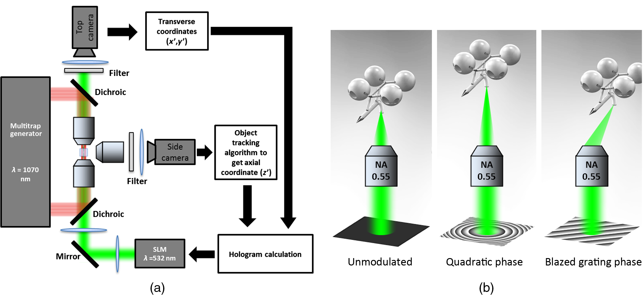 The required phase holograms for the lateral and axial movements of each coupling beam are calculated using the simplified “blazed grating and quadratic phases” approach, and are given by where is the focal length of the applied Fourier transforming lens. This approach is rather similar to that used for holographic optical tweezers2,17 except that we are using it for coupling light through the light-guiding microtool. We reserve the primed coordinates for the sample plane and the unprimed coordinates for the plane of the SLM. In some cases, an offset is necessary to have a convenient coordinate for both the trapping beams and the coupling beams. Thus, the effective phase for a single coupling beam is given by The holographic coupling to a microtool can be visualized as shown in Fig. 2(b).2.3.Experimental Setup with a Generalized Phase Contrast Light ShaperThe biophotonics workstation uses a counter-propagating beam-trapping geometry. The top and bottom trapping beams are relayed into the sample by two long working distance and low-NA objectives (Olympus LMPL IR objectives, , and ). A side-view imaging objective lens (Mitutuyo MPlanApo , , and ) is added for more intuitive 3-D trapping and for capturing the emerging output beam from the tip of each microtool. The setup is described in Fig. 2(a). A fluorescence dye (Rhodamin 6G) is added to the trapping medium to aid in visualizing the coupling beams using the side-view imaging. The holographic setup uses a single focusing geometry where the phase patterns are projected to an LCoS SLM (Hamamatsu Photonics, , active area). To increase the efficiency of the coupling beams, a preliminary beam shaping using the GPC method18 is performed to match the cross section of the SLM addressing window. A compact module containing the main components of the GPC is added to the holographic setup as shown in Fig. 3. We refer to this module as the so-called GPC light shaper (LS). The sizes of the phase mask and phase contrast filter are optimized according to the values in the literature.19 The use of the GPC LS allows efficient photon management compared to the more common practice of hard-truncation20,21 and can work with a broad range of wavelengths.22 Fig. 3Schematic diagram of the holographic coupling light setup. The GPC light shaper (LS) is placed before the spatial light modulator (SLM) to perform preliminary beam shaping to match the shape of the SLM. Unlike hard-truncation where a significant portion of light is discarded, the GPC LS only redirects photons to the active SLM window. 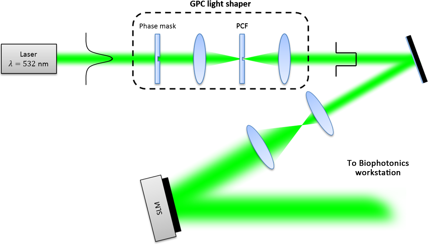 The GPC LS works by introducing a phase shift to the incident Gaussian beam using a phase mask that has a phase shifting region corresponding to the shape of the SLM. A lens takes the optical Fourier transform of the phase shifted field in the plane of the phase contrast filter which creates a synthetic reference wave from the low spatial frequencies. A second lens takes another optical Fourier transform of the field and the resulting pattern at the output plane is a speckle-free intensity distribution corresponding to the layout of the input phase mask. Unlike the common method of hard-truncation where photons are discarded, the GPC LS redirects photons to where they are needed. The holographic setup with the integrated GPC LS is shown in Fig. 3. 3.Experimental Results3.1.Image SegmentationA long-pass filter with a cutoff wavelength at 550 nm is placed before the applied CMOS camera to remove the coupling beams and use the fluorescence signal to measure the total power output at the tip of the microtool. We use an image segmentation approach based on the color channel of the captured images to ensure that we compute only the fluorescence signal. We take advantage of the RGB color model used to represent the captured images. The RGB color model is an additive model where different colors are produced by mixing the three primaries (i.e., red, green, and blue).23 A cyan filter is installed with the white LED for the side illumination. The resulting cyan color illumination registers in the CMOS camera as having an RGB value of (0, 255, 255) and the microtools are practically transparent. Thus, the greenish fluorescence signal will result in localized variations in the red channel only. Figure 4 shows a particularly good localization of the fluorescence signal at the tip of the microtool. Furthermore, we can calculate the “center of mass” from the red channel data to pinpoint the location of the tip and integrate the total power within the vicinity. This procedure is similar to tracking fluorescent low density lipoprotein receptor molecules.24 3.2.Brownian Motion of the Trapped MicrostructureA crucial step for optimal coupling is to account for the uncontrolled movement of the trapped microstructures due to Brownian motions. We measure the amount of fluctuations of each microtool by trapping it in a fixed position and use the output coupling beam at the tip as a light beacon to locate its position. The trajectories for both GPC-enhanced and non-GPC coupling beams are plotted in Figs. 5(a) and 5(b), respectively. Fig. 5Brownian motion trajectories for (a) GPC-enhanced and (b) a non-GPC coupled microtool. (c) Power variations at the output are observed. The dashed lines represent the average power for both coupling cases. 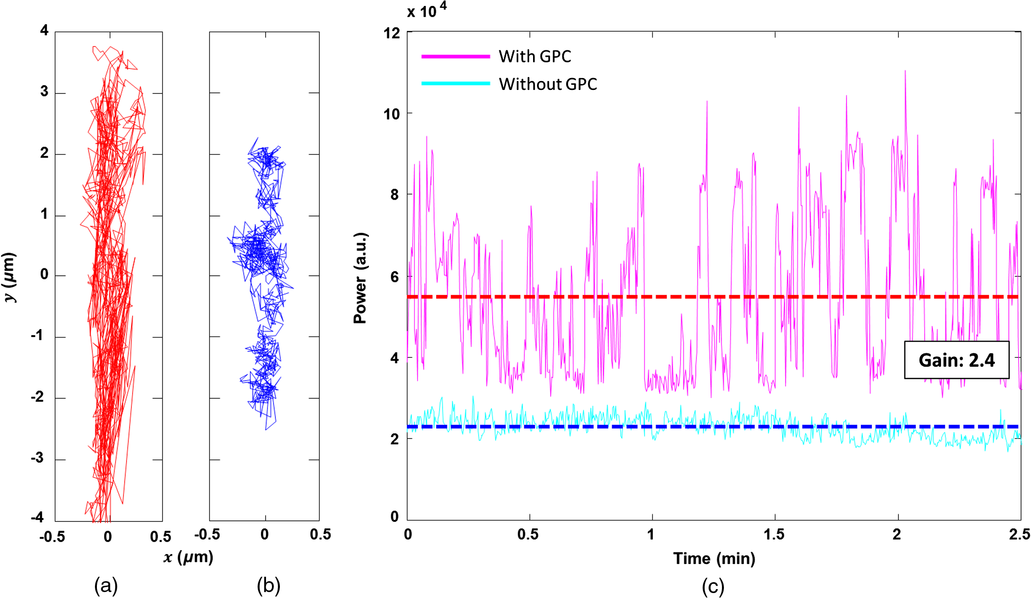 In both coupling cases, there is a small movement along the lateral direction, but a large variance along the axial direction. This is due to the relatively weak axial confinement obtained by low-NA counter-propagating beam traps. However, there are more pronounced fluctuations in the GPC-enhanced coupled microtool. We attribute this to the stronger recoil of the structure from the more intense coupling beam.25 This effect can be minimized by modifying the shape of the handles.5,26 Figure 5(c) shows the output power fluctuations for the duration of our observation. We took the average power for both coupling cases and took the ratio to calculate the gain. We found the value to be 2.4 for a GPC-enhanced coupled microtool. 3.3.Coupling Through Optically Manipulated MicrostructureCoupling has been tested for both lateral and axial displacements of the microtools, separately. The lateral movement is performed by dragging its associated trap using a computer interface. The coordinate variables are then grabbed to calculate the required grating phase. For axial coupling, the position of a microtool is obtained from the built-in object tracking routine in LabVIEW. The obtained axial displacement is then used to calculate the required quadratic (lens) phase. The results for the lateral and axial coupling are shown in Figs. 6 and 7, respectively. The total power for each case is calculated frame by frame for the duration of the observations () and the average power for each coupling case is taken to compute the gain. Fig. 6(a) Power variations as a microtool are moved laterally. The dashed lines represent the average power value. (b) Selected frames are stacked together to form a trace of the trajectory of the microtool while it is being optically manipulated. (Video 1, QuickTime, 4.66 Mb.) [URL: http://dx.doi.org/10.1117/1.OE.54.11.111308.1]. 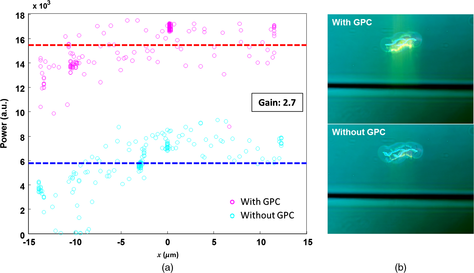 Fig. 7(a) Power variations as a microtool are moved axially. The dashed lines represent the average power value. (b) Selected frames are stacked together to form a trace of the trajectory of the microtool while it is being optically manipulated. (Video 2, QuickTime, 4.49 Mb.) [URL: http://dx.doi.org/10.1117/1.OE.54.11.111308.2].  In both lateral and axial coupling experiments, the GPC-enhanced coupled microtools show the highest total output power. This boost in output tip-light from the microtools can have potential applications when the aim is to trigger nonlinear light phenomena in biological samples. The microtools can be coated with gold nanoparticles to trigger local field enhancement for a better fluorescence signal.27 In Fig. 8, we demonstrate coupling following an arbitrary path. Fig. 8Trapping and coupling of a microtool tracing out an arbitrary path. Selected frames are stacked together to form a trace of the path. (Video 3, QuickTime, 584 Kb.) [URL: http://dx.doi.org/10.1117/1.OE.54.11.111308.3].  4.Conclusions and OutlookWe have experimentally demonstrated real-time continuous coupling of green laser light to near-infrared laser-trapped and manipulated a microtool, coined as wave-guided optical waveguides, by using an object tracking algorithm. The addition of our GPC LS in the diffractive setup allows for an efficient formation of high intensity light spots that are particularly suitable when simultaneously addressing a plurality of moving microtools. We have obtained an output gain of up to 2.7 times and this complements well with the targeted-light delivery capability of the microtools. The ability to switch between on-demand and continuous high intensity coupling offers versatility for the light-guiding microtools for potential applications in photostimulation and near-field excited nonlinear optics. AcknowledgmentsThis work has been supported by the Enhanced Spatial Light Control in Advanced Optical Fibres (e-space), a project financed by the Innovation Fund Denmark (Grant No. 0603-00514B). We also acknowledge the support from Hamamatsu Photonics Central Research Laboratories. ReferencesA. Ashkin,
“Acceleration and trapping of particles by radiation pressure,”
Phys. Rev. Lett., 24
(4), 156
(1970). http://dx.doi.org/10.1103/PhysRevLett.24.156 PRLTAO 0031-9007 Google Scholar
J. E. Curtis, B. A. Koss and D. G. Grier,
“Dynamic holographic optical tweezers,”
Opt. Commun., 207
(1–6), 169
–175
(2002). http://dx.doi.org/10.1016/S0030-4018(02)01524-9 OPCOB8 0030-4018 Google Scholar
D. Palima and J. Glückstad,
“Gearing up for optical microrobotics: micromanipulation and actuation of synthetic microstructures by optical forces,”
Laser Photonics Rev., 7
(4), 478
–494
(2013). http://dx.doi.org/10.1002/lpor.201200030 Google Scholar
J. Glückstad,
“Optical manipulation: sculpting the object,”
Nat. Photonics, 5
(1), 7
–8
(2011). http://dx.doi.org/10.1038/nphoton.2010.301 NPAHBY 1749-4885 Google Scholar
D. B. Phillips et al.,
“An optically actuated surface scanning probe,”
Opt. Express, 20
(28), 29679
–29693
(2012). http://dx.doi.org/10.1364/OE.20.029679 OPEXFF 1094-4087 Google Scholar
S. Fukada et al.,
“3D fabrication and manipulation of hybrid nanorobots by laser,”
in IEEE Int. Conf. Robotics and Automation,
(2013). Google Scholar
P. J. Rodrigo et al.,
“GPC-based optical micromanipulation in 3D real-time using a single spatial light modulator,”
Opt. Express, 14
(26), 13107
–13112
(2006). http://dx.doi.org/10.1364/OE.14.013107 OPEXFF 1094-4087 Google Scholar
P. J. Rodrigo et al.,
“Optical microassembly platform for constructing reconfigurable microenvironments for biomedical studies,”
Opt. Express, 17
(8), 6578
–6583
(2009). http://dx.doi.org/10.1364/OE.17.006578 OPEXFF 1094-4087 Google Scholar
H.-U. Ulriksen et al.,
“Independent trapping, manipulation and characterization by an all-optical biophotonics workstation,”
J. Eur. Opt. Soc. Rapid Publ., 3 08034
(2008). http://dx.doi.org/10.2971/jeos.2008.08034 Google Scholar
G. Thalhammer et al.,
“Optical macro-tweezers: trapping of highly motile micro-organisms,”
J. Opt., 13
(4), 044024
(2011). http://dx.doi.org/10.1088/2040-8978/13/4/044024 Google Scholar
D. Palima et al.,
“Wave-guided optical waveguides,”
Opt. Express, 20
(3), 2004
–2014
(2012). http://dx.doi.org/10.1364/OE.20.002004 OPEXFF 1094-4087 Google Scholar
M. Villangca et al.,
“Dynamic diffraction-limited light-coupling of 3D-maneuvered wave-guided optical waveguides,”
Opt. Express, 22
(15), 17880
–17889
(2014). http://dx.doi.org/10.1364/OE.22.017880 OPEXFF 1094-4087 Google Scholar
A. Melloni et al.,
“Determination of bend mode characteristics in dielectric waveguides,”
J. Lightwave Technol., 19
(4), 571
–577
(2001). http://dx.doi.org/10.1109/50.920856 JLTEDG 0733-8724 Google Scholar
J. Kerttula et al.,
“Mode evolution in long tapered fibers with high tapering ratio,”
Opt. Express, 20
(23), 25461
–25470
(2012). http://dx.doi.org/10.1364/OE.20.025461 OPEXFF 1094-4087 Google Scholar
K. Fukunaga and L. Hostetler,
“The estimation of the gradient of a density function, with applications in pattern recognition,”
IEEE Trans. Inf. Theory, 21
(1), 32
–40
(1975). http://dx.doi.org/10.1109/TIT.1975.1055330 IETTAW 0018-9448 Google Scholar
D. Comaniciu and P. Meer,
“Mean shift: a robust approach toward feature space analysis,”
IEEE Trans. Pattern Anal. Mach. Intell., 24
(5), 603
–619
(2002). http://dx.doi.org/10.1109/34.1000236 ITPIDJ 0162-8828 Google Scholar
J. Liesener et al.,
“Multi-functional optical tweezers using computer-generated holograms,”
Opt. Commun., 185
(1–3), 77
–82
(2000). http://dx.doi.org/10.1016/S0030-4018(00)00990-1 OPCOB8 0030-4018 Google Scholar
J. Glückstad and D. Palima, Generalized Phase Contrast: Applications in Optics and Photonics, Springer Series in Optical Sciences, Netherlands
(2009). Google Scholar
A. Bañas et al.,
“GPC light shaper for speckle-free one- and two-photon contiguous pattern excitation,”
Opt. Express, 22
(5), 5299
–5310
(2014). http://dx.doi.org/10.1364/OE.22.005299 OPEXFF 1094-4087 Google Scholar
A. Bañas et al.,
“GPC light shaper: static and dynamic experimental demonstrations,”
Opt. Express, 22
(20), 23759
–23769
(2014). http://dx.doi.org/10.1364/OE.22.023759 OPEXFF 1094-4087 Google Scholar
M. Villangca et al.,
“GPC-enhanced read-out of holograms,”
Opt. Commun., 351 121
–127
(2015). http://dx.doi.org/10.1016/j.optcom.2015.04.057 OPCOB8 0030-4018 Google Scholar
O. Kopylov et al.,
“GPC light shaping a supercontinuum source,”
Opt. Express, 23
(3), 1894
(2015). http://dx.doi.org/10.1364/OE.23.001894 OPEXFF 1094-4087 Google Scholar
C. Poynton, Digital Video and HDTV Algorithms and Interfaces, Morgan Kaufmann Publishers Inc., San Francisco, California
(2003). Google Scholar
R. N. Ghosh and W. W. Webb,
“Automated detection and tracking of individual and clustered cell surface low density lipoprotein receptor molecules,”
Biophys. J., 66
(5), 1301
–1318
(1994). http://dx.doi.org/10.1016/S0006-3495(94)80939-7 BIOJAU 0006-3495 Google Scholar
D. Palima et al.,
“Optical forces through guided light deflections,”
Opt. Express, 21
(1), 581
–593
(2013). http://dx.doi.org/10.1364/OE.21.000581 OPEXFF 1094-4087 Google Scholar
D. B. Phillips et al.,
“Shape-induced force fields in optical trapping,”
Nat. Photonics, 8
(5), 400
–405
(2014). http://dx.doi.org/10.1038/nphoton.2014.74 NPAHBY 1749-4885 Google Scholar
B. L. Aekbote et al.,
“Gold nanoparticle-mediated fluorescence enhancement by two-photon polymerized 3D microstructures,”
Opt. Mater., 38 301
–309
(2014). http://dx.doi.org/10.1016/j.optmat.2014.10.064 OMATET 0925-3467 Google Scholar
BiographyMark Villangca finished his master’s degree in physics at the University of the Philippines while working on beam shaping using computer-generated holograms. Currently, he is taking his PhD in photonics engineering at the Technical University of Denmark as a member of the programmable phase optics group. He now works with generalized phase contrast and digital holography for beam shaping, two-photon fabrication of microtools, and optical manipulation. Andrew Bañas earned his PhD from DTU Fotonik. His works with the programmable phase optics group have been featured in optics express and OPN. These include applying Fourier optics or electrodynamics to get the most out of experiments. He has also designed and built hardware and software for beam shaping and optical manipulation systems. Currently, he is pursuing tech-transfer activities which include applications of generalized phase contrast and cell sorting for studying disease. Darwin Palima works as an associate professor at DTU Fotonik, Technical University of Denmark. He received his PhD in physics from the University of Philippines and moved to Denmark to work as a postdoc. He co-authored a book on generalized phase contrast and actively publishes in peer-reviewed journals and conference proceedings. He teaches biophotonics and optical engineering while pursuing research interests that include computer-generated holograms, generalized phase contrast, optical trapping and micromanipulation, and microscopy and biophotonics applications. Jesper Glückstad is a professor at DTU Fotonik and 5-year guest professor in biophotonics at Lund Institute of Technology, 2006 to 2011. He established www.ppo.dk, received the Danish Optical Society Award in 2000, and was elected “Scientist of the Year” in 2005 by Dir. Ib Henriksen’s Foundation in Denmark. He is a fellow of the OSA and SPIE as the first from Denmark and founder of OptoRobotix.com in 2011. Most recently, he is a founder of GPCphotonics.com. |


