|
|
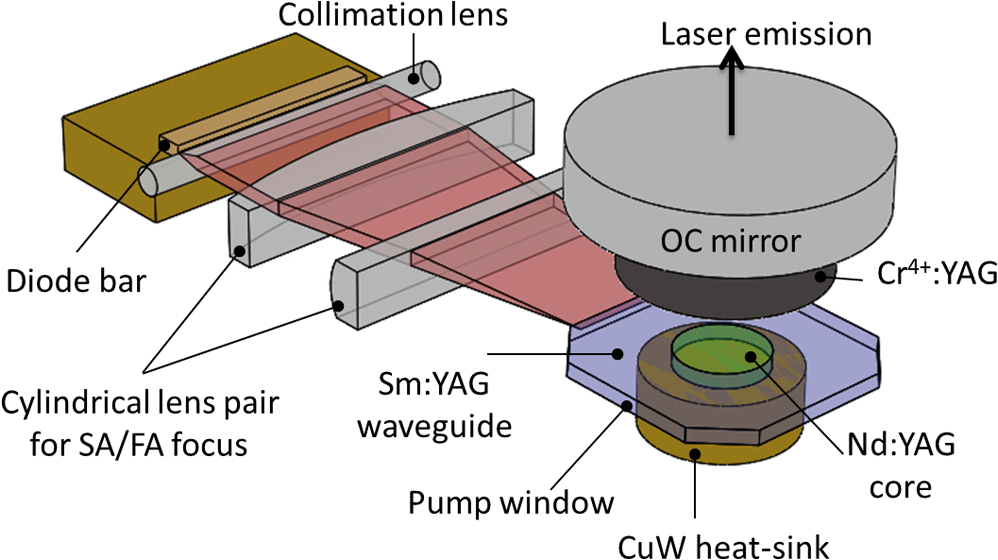
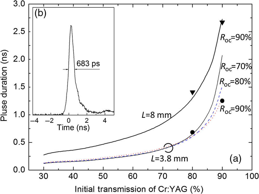
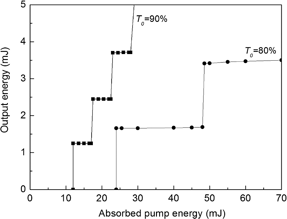
1.IntroductionCompact, passive Q-switched lasers have found extensive use in applications requiring high laser intensities with subnanosecond pulses, such as microprocessing, remote sensing, laser ignition, and intense UV generation. Most of the passive Q-switched lasers are based on the end-pump configuration, which may suffer from thermal problems.1,2 In this context, the technique of diode edge-pumping is a unique pumping method that can be used to realize the separation of the pump, laser, and cooling interface in a passive Q-switched lasing setup. The separation makes laser operation easy, and cooling of the gain medium becomes effective. In a previous work, we have demonstrated an output power of 414 W (continuous wave) in an edge-pumped all-ceramic microchip laser.3 Further, gain-guiding and transverse mode control in a lens-less edge-pumped microchip laser have also been demonstrated in other studies.4,5 In comparison with a thin-disk laser,6 which applies the same cooling method, the edge-pump configuration is more flexible because the laser emission side is not blocked by the pumping beams, thus it is possible to position intracavity elements for optical switching or nonlinear operation. Recently, we have reported on laser ignition7 in a quasi-continuous-wave (QCW) diode pump laser with as the saturable absorber. The edge-pumped microchip is considered to be suitable for this type of high-peak-power passively Q-switched laser because the microchip has a large gain aperture by which to obtain a large mode size for high-power operation. Further, the use of the low-duty QCW pump and face cooling allow the realization of a water-free laser system. Nowadays, it is common to use a composite ceramic material for laser medium design. Other work has applied a composite rod for an end-pumped passively Q-switched laser in which the cladding supports amplified spontaneous emission (ASE) suppression of parasitic ring modes at 1064 nm.8 In the edge-pumped microchip laser, it is also important to suppress ASE and parasitic oscillations. The microchip has four polished pump windows, which could become parasitic oscillation cavity mirrors. 2.Experimental Setup and ResultsIn our setup, four commercial QCW diode bars (emitting laser light at 808 nm) with far-axis collimation lenses are utilized as the pump source, and the diode bars pump light from four directions in order to realize uniform gain. The size of the pump beam after passing through the collimation lens is about 10 mm long and 1 mm wide. The schematic of pumping along only one direction is shown in Fig. 1 for the purpose of simplicity; the other three directions are omitted. The pulse duration of the diode laser is adjustable in the range from 50 to , and the diode peak power is maintained constant at 200 W for each. The pump energy is varied by adjusting the pulse duration with the pump repetition rate being set to 10 Hz. A cylindrical lens pair is used to focus the pump beam into the edge of the microchip (indicated as the pump window in Fig. 1). The focal lengths of the slow-axis and fast-axis focusing lenses are 25 and 6 mm, respectively. The size of the pump beam at the pump window is estimated to be about 4 mm long with a width of several micrometers. As the thickness of microchip is 0.25 mm, it is easy to couple most of the pump beam inside the microchip. As regards the microchip, we use a composite all-ceramic microchip bonded on a copper–tungsten heat sink. The central cylindrical core (diameter of 2 mm) comprises 1.5 at.% Nd-doped ceramic YAG, and the surrounding square cladding (length of 8 mm) comprises 5 at.% Sm-doped ceramic YAG. The cladding has four “dull-polished” corners for suppressing parasitic oscillations due to total internal reflection. The cladding is not only utilized as a waveguide but also to absorb the ASE at 1064 nm. The sample is measured to be fully transparent for 808 nm, and it strongly absorbs light at 1064 nm with an absorption coefficient of . Figure 2 shows the fluorescence image of the four-direction-pumped microchip as obtained by a charge-coupled device camera. The dotted circle indicates the Nd:YAG core area, and the arrow indicates ASE suppression by the cladding. The three-dimensional fluorescence image in Fig. 2(b) shows the resulting top-hat pump profile. Compared with our preliminary result, which only applied a two-direction pump,9 a more uniform gain-shape can be achieved. With the aid of a four diodes pump, we can further examine the ASE suppression. No parasitic oscillations occur (Fig. 2) even with “intense” pumping, because parasitic oscillations will consume the fluorescence leading to a nonuniform fluorescence pattern. Fig. 2(a) Two-dimensional and (b) three-dimensional fluorescence images of four-direction-pumped microchip. The dotted circle indicates the Nd:YAG core area, whereas the arrow indicates the suppression of amplified spontaneous emission (ASE) by the cladding.  In our study, the performance of the passively Q-switched laser was examined using a flat-concave laser cavity. As regards the cavity, a high reflectivity coating and high transmissivity (HT) coating (corresponding to a wavelength of 1064 nm) are deposited at the bottom and top surfaces of the microchip, and 1-mm-thick is deposited between the microchip and a concave output coupler (OC) with a radius of curvature (ROC) of 2 m. Further, both sides of the layer are HT coated for transmission at 1064 nm. The initial transmission values of are set to and with an OC reflectivity of in the experiment. For smaller values of and or for a flat OC mirror, we cannot obtain laser oscillations because the gain in the thin microchip is insufficient under these conditions. The smallest optical cavity length that can be realized is because of the cavity’s mechanical limit: the commercial mirror holder cannot be closer to microchip. Figure 3 shows the pulse duration as a function of the initial transmission of the layer when the optical cavity lengths are 8 and 3.8 mm. In our study, we followed the simulation method presented in Refs. 1011.–12; the lines in the figure indicate the simulation results, whereas the filled symbols indicate the experimental results for . As mentioned above, we did not obtain laser oscillations for ; hence, there are no corresponding experimental results in Fig. 3. The calculated results indicate that smaller and values lead to the generation of pulses with widths smaller than 200 ps; moreover, the value does not influence the pulse width significantly when . In our experiment, we achieved a pulse width of 683 ps for , , and . The resulting pulse profile is shown in Fig. 3(b) as measured by a 12-GHz oscilloscope (Agilent DSO81204B) and 10-GHz InGaAs detector (EOT Inc., ET-3500). Figure 4 shows the output laser energy as a function of the absorbed pump energy in the flat-concave cavity for parameter values of , , and . The figure depicts the step output characteristic of passively Q-switched lasers: the output pulse energy does not increase until the next pulse is generated. From the figure, we observe that the single-pulse energy values are 1.25 and 1.66 mJ when and , respectively. Further, in both cases, the beam quality is measured to be , which has improved compared with our preliminary result.9 This resulting poor beam quality is attributed to the use of the flat-concave cavity with an unsuitable cavity length. We had applied different OC mirrors and obtained the result: for , the pulse energy is 1.89 mJ and ; for , the pulse energy is 1.78 mJ and . In the case of a big mode size and short cavity length, the beam quality can be significantly improved with the use of a “flat–flat” cavity. 10,13 The primary challenges in this regard include realizing an increased gain in the thin microchip. Both special laser diodes of high pump-power and a coupling technique for the microchip are needed to achieve millimeter cavity lengths. 3.ConclusionWe have reported the demonstration of an edge-pumped passively Q-switched microchip laser. A composite ceramic microchip was used to obtain an edge-pump configuration, and a cladding was utilized both as waveguide and ASE absorber. In laser operation, single-pulse energy of 1.66 mJ was achieved when the absorbed pump energy was 24 mJ. The pulse duration was 683 ps with a repetition rate of 10 Hz. In order to achieve higher pulse energies and shorter pulses, more gain needs to be realized in the microchip for laser operation with smaller values of and . Moreover, a flat–flat laser cavity can also improve the beam quality. We believe that our approach can significantly extend the range of application of the compact microchip laser. AcknowledgmentsThe authors would like to thank JST (Japan Science and Technical Agency) for funding support. Further, the authors also thank Mr. T. Kondo of the Institute for Molecular Science (Japan) for his cooperation and support. ReferencesJ. J. Zayhowski,
“Passivley Q-switched microchip lasers and applications,”
Rev. Laser Eng., 26 841
(1998). http://dx.doi.org/10.2184/lsj.26.841 Google Scholar
J. J. Zayhowski,
“Microchip lasers,”
Opt. Mater., 11 255
(1999). http://dx.doi.org/10.1016/S0925-3467(98)00048-2 OMATET 0925-3467 Google Scholar
M. Tsunekane and T. Taira,
“High-power operation of diode edge-pumped, composite all-ceramic microchip laser,”
Appl. Phys. Lett., 90 121101
(2007). http://dx.doi.org/10.1063/1.2714099 APPLAB 0003-6951 Google Scholar
W. Kong and T. Taira,
“Lens-less edge-pumped high-power microchip laser,”
Appl. Phys. Lett., 100 141105
(2012). http://dx.doi.org/10.1063/1.3699225 APPLAB 0003-6951 Google Scholar
W. Kong, A. Sugita and T. Taira,
“Generation of Hermite-Gaussian modes and vortex arrays based on two-dimensional gain distribution controlled microchip laser,”
Opt. Lett., 37 2661
(2012). http://dx.doi.org/10.1364/OL.37.002661 OPLEDP 0146-9592 Google Scholar
A. Giesen et al.,
“Scalable concept for diode-pumped high-power solid-state lasers,”
Appl. Phys. B, 58 365
(1994). http://dx.doi.org/10.1007/BF01081875 Google Scholar
N. Pavel, M. Tsunekane and T. Taira,
“Composite, all-ceramics, high-peak power monolithic micro-laser with multiple-beam output for engine ignition,”
Opt. Express, 19 9378
(2011). http://dx.doi.org/10.1364/OE.19.009378 OPEXFF 1094-4087 Google Scholar
R. Huß et al.,
“Suppression of parasitic oscillations in a core-doped ceramic laser by cladding,”
Opt. Express, 18 13094
(2010). http://dx.doi.org/10.1364/OE.18.013094 OPEXFF 1094-4087 Google Scholar
M. Tsunekane and T. Taira,
“Diode edge-pumped, composite ceramic microchip lasers,”
in OSA/FiO/LS, XXVI, OSA Technical Digest (CD),
(2010). Google Scholar
H. Sakai, H. Kan and T. Taira,
“ peak power single-mode high-brightness passively Q-switched microchip laser,”
Opt. Express, 16 19891
(2008). http://dx.doi.org/10.1364/OE.16.019891 OPEXFF 1094-4087 Google Scholar
J. J. Degnan,
“Optimization of passively Q-switched lasers,”
IEEE J. Quantum Electron., 31 1890
(1995). http://dx.doi.org/10.1109/3.469267 IEJQA7 0018-9197 Google Scholar
N. Pavel et al.,
“High average power diode end-pumped composite Nd:YAG laser passively Q-switched by saturable absorber,”
Jpn. J. Appl. Phys., 40 1253
(2001). http://dx.doi.org/10.1143/JJAP.40.1253 Google Scholar
M. Tsunekane and T. Taira,
“High peak power, passively Q-switched micro-lasers,”
IEEE J. Quantum Electron., 49 454
(2013). http://dx.doi.org/10.1109/JQE.2013.2252327 Google Scholar
|