|
|
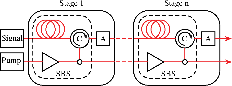
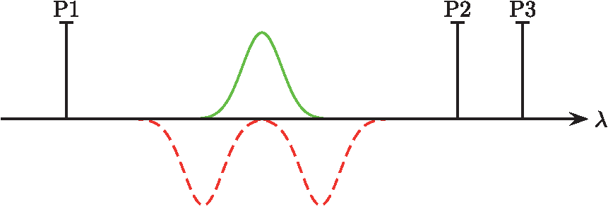
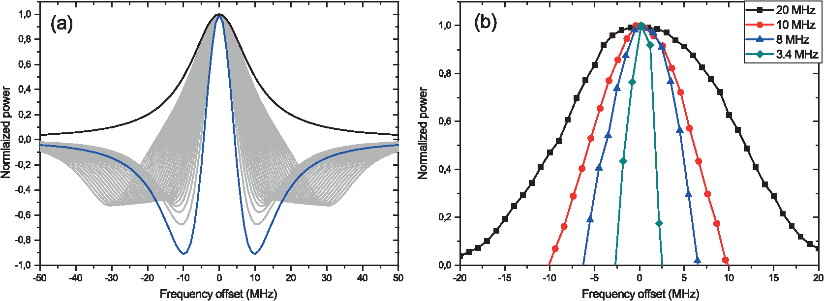
1.IntroductionMicrowave photonics, which brings together the worlds of radio-frequency engineering and optoelectronics, has attracted great interest from both the research community and the commercial sector over the past decades.1–3 The technology makes it possible to have functions in microwave systems that are complex or even not directly possible in the radio-frequency domain and also creates new opportunities for applications such as radar, communication systems, sensor networks, and instrumentation. In general, the microwave photonics techniques cover the photonic generation of microwave signals, photonic processing and distribution of microwave signals, and photonic analog-to-digital conversion. Microwave photonics provides a promising solution for the processing of high-frequency and broadband microwave signals, as it overcomes the bottle neck due to the limited sampling speed of digital electronics. Other advantages of processing microwave signals in the optical domain include large tunability, reconfigurability, and immunity to electromagnetic interference. Various photonic components have been employed in microwave photonics systems, such as optical sources, optical amplifiers, dispersive elements, electro-optical modulators, optical filters, and photodetectors. Most microwave photonics systems are designed to operate at the 1550 nm band, to take advantage of the low-cost photonic devices developed for fiber optic communications in this wavelength band. One of the most important microwave photonics subsystems for the processing of radio frequency, microwave, and millimeter-wave signals in the optical domain are optical filters. The ultimate goal of a filter is to improve the signal-to-noise ratio of the signal of interest either by rejecting unwanted signals or by allowing only the desired signal to propagate to the detector and thus, reducing the received bandwidth. While commercial optical filters with single band-reject or band-pass resonances provide wide tunability, their bandwidth is typically in the order of tens of GHz, which is much larger than desirable for a number of applications. Fiber Bragg gratings (FBG) achieve bandwidths down to 5 GHz with a tuning range over 10 nm or 1.27 THz, for instance. The filter characteristic is Butterworth shaped, which leads to steep edges and a good out-of-band suppression. Recently, manufacturers have introduced FBG with ultranarrow bandwidths of 100 MHz, but the tuning range is limited to 20 GHz. A special type of grating-based filter is a wave shaper, which utilizes spatial light modulators. It can operate over a large frequency range and can be programmed individually with a bandwidth down to 10 GHz. The Gaussian filter characteristic makes them suitable as prefilter, in order to extract a small part out of a large spectrum. Furthermore, Fabry–Perot (FP) filters can be used, which utilize the interference of light bouncing within a cavity. The filter characteristic has a Lorentzian shape. Due to the cavity, a FP filter has a periodic structure. Therefore, the free spectral range (FSR) of an FP is very important. Commercially available devices achieve bandwidths of at 1550 nm with an FSR of up to 51 GHz. Unfortunately, the bandwidth varies independent of the wavelength. Therefore, custom devices are necessary to cover a large frequency range. Additionally, the fabrication process for narrow bandwidths is technically challenging. The visualization of the bandwidth for different filter realizations can be seen in Fig. 1. Fig. 1Frequency response for different filter types. WS: wave shaper, FBG: fiber Bragg grating, FP: Fabry-Perot, SBS: stimulated Brillouin scattering. 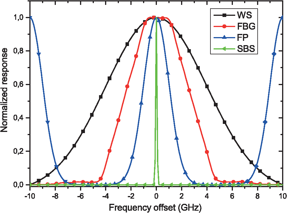 A different approach for filtering in the optical domain utilizes the nonlinear effect of stimulated Brillouin scattering (SBS). SBS is a nonlinear process that occurs in optical fibers, which results in a back-scattered Stokes wave with narrow bandwidth, in the range of tens of MHz, and a frequency shift around 10 GHz.4 Although detrimental for optical communications due to its low threshold, it has been shown that SBS can be controlled and harnessed for a wide range of radio-frequency signal processing applications. The unique characteristics of the SBS process and the achievable high gain enable a narrowband filtering over a large tuning range independent of the pump laser source used, as well as the used fiber as medium for the interaction. The bandwidth, gain profile, and wavelength of the SBS process can be controlled, however, by tailoring the pump profile. SBS-based gain and absorption resonances therefore provide a flexible way to realize a widely tunable, reconfigurable optical filter. Several applications such as wideband phase shifting,5 tunable true time delay,6,7 and microwave photonic filtering,8–10 among others, have been demonstrated. The further reduction of the bandwidth would enable significant advantages for several applications in the field of microwave photonics and optical signal processing. This contribution gives a short introduction to the nonlinear effect of SBS with its unique properties. The main focus will be on several methods for the reduction of the SBS gain bandwidth. Afterward, different applications that benefit from a narrower gain bandwidth will be introduced. This includes the spectroscopy of optical and microwave signals, the quasi-light-storage (QLS) of optical data packets, and the processing of optical frequency combs, including high-quality mm-wave and ideal sinc-shaped Nyquist pulse generation. 2.Stimulated Brillouin ScatteringThe SBS is the most dominant nonlinear process that occurs in optical fibers at relatively low-input powers.11,12 In principle, SBS is based on an interaction of an incident light wave (pump wave) with the optical medium, as shown in Fig. 2. Density fluctuations inside the optical fiber or thermoelastic motions of the molecules cause scattering of parts of the incident light wave into the backward direction. The back-scattered wave is called Stokes wave. This Stokes wave superposes with the pump wave, which builds up an electrical interference field. Due to the process of electrostriction, the interference pattern leads to a periodical density modulation of the medium. The density modulation can be seen as a modulation of the refractive index, which acts like a moving Bragg grating. If the Bragg condition is fulfilled, more power of the pump wave is back-scattered. This leads to a stronger density modulation, which in turn exponentially increases the Stokes wave. The process continues and more and more optical power of the pump wave is backscattered and transferred to the Stokes wave. The Brillouin scattering effect becomes stimulated if the reason for the density modulation is the pump wave itself, and the pump power exceeds a certain threshold.4,13 As long as the optical pump power supply is sufficiently strong and can compensate for the pump power decrease due to the creation of the density modulation, the SBS process is self-preserving. Fig. 2Generation of an acoustic wave due to the superposition of the forward propagating pump wave with the back-scattered Stokes wave.  The density modulation of the medium can be seen as acoustic phonons or an acoustic wave, because it propagates with the speed of sound into the direction of the pump wave. Due to the relative velocity between the pump and the acoustic wave, the frequency or wavelength of the Stokes wave is shifted according to the Doppler effect. This frequency or wavelength shift is called Brillouin shift and is typically in the range of 10 GHz. In a standard single-mode fiber (SSMF), a pump wave generates a gain for counter-propagating pulses if they are down-shifted in frequency by . For up-shifted counter-propagating pulses, the same pump wave generates a loss. The gain of the SBS process has a Lorentzian shape and can be written as14 with as the full width at half maximum (FWHM) bandwidth of the spontaneous Brillouin scattering, as the angular frequency of the line center, and as the line center gain, which can be expressed by14 where is the peak value of the SBS gain coefficient, is the input pump power, is the effective length, and is the effective area of the fiber. With respect to a pump wavelength of 1550 nm, as used in optical telecommunication, in SSMF the bandwidth of the gain is usually in the range of 20 to 30 MHz, depending on strain, temperature, and possible dopants. According to Eq. (1), for , the bandwidth of the SBS gain can be calculated byAs mentioned before, an adaption of the gain bandwidth is important and necessary for many applications. A simple broadening of the gain can be achieved with various techniques, enabling broadband gain response in the GHz range. They include the modulation of the pump laser source itself15,16 or the utilization of a multiple wavelength pump source, where the different wavelengths have a spacing below the SBS bandwidth.17,18 In contrast, many applications like ultranarrowband optical filters,15 high-resolution spectroscopy of optical and microwave signals,19 and the storage of optical data signals (QLS)20–22 require a very narrow bandwidth. Within the spectroscopy, the bandwidth of SBS directly defines the achievable resolution. All frequency components beneath the SBS bandwidth cannot be correctly displayed. Similarly, the inverse of the SBS bandwidth defines the maximum storage time of the QLS. All of these applications would benefit from a narrower Brillouin gain bandwidth. 3.Stimulated Brillouin Scattering Bandwidth ReductionThe gain bandwidth reduction of SBS can be realized by several approaches. Some of them are capable of reducing the gain down to 15% of its original value. On the first sight, there are two obvious possibilities. According to Eqs. (2) and (3), the gain bandwidth can be decreased by a higher pump power or a longer effective length of the fiber. This narrowing of the Stokes bandwidth is well known.23,24 The calculated and measured SBS bandwidth in dependence of the pump power can be seen in Fig. 3(a). Within the calculations, the values , , , and are used.25 The measurement was carried out for a 20 km long AllWave fiber with an attenuation of and a Brillouin threshold of 5.5 dBm. Below the threshold, the gain bandwidth is, as expected, much broader. Above the threshold, and clearly in the stimulated process, it approaches a constant value around 10 MHz. The measured gain profiles for two exemplary chosen pump powers of 1 and 15 dBm can be seen in Fig. 3(b). The measured bandwidth for a pump power of 1 dBm is 23 MHz and for a pump power of 15 dBm is reduced to 10.3 MHz. Fig. 3(a) Comparison of the theoretical values of the SBS gain bandwidth for different pump powers with the measured values and (b) the measured gain profile for pump powers of 1 dBm and 15 dBm. 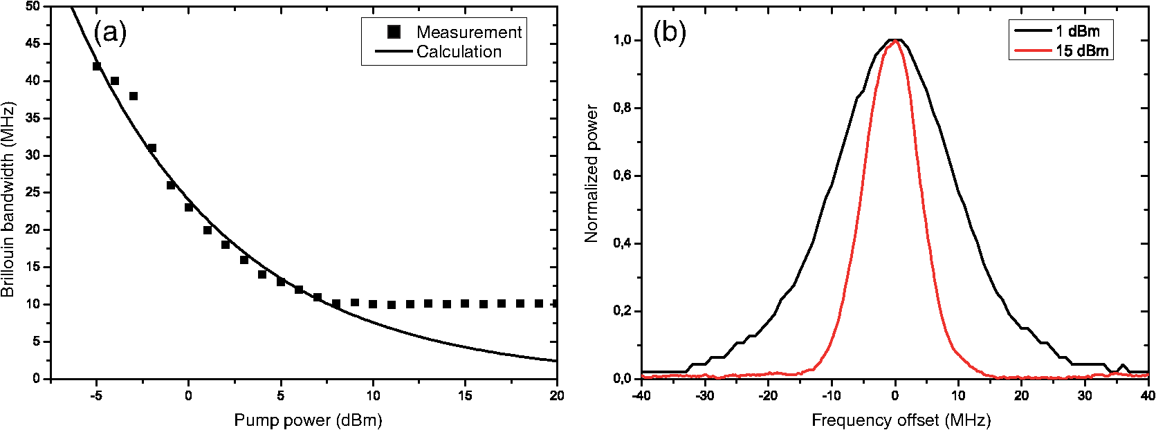 However, as with every amplification process, the SBS shows saturation. Thus, the maximum achievable gain is restricted to .26,27 Hence, the minimum bandwidth for high pump powers is around 10 MHz,28 which is also defined by the phonon lifetime of in commonly used optical materials. Unfortunately, the increase of the SBS-related noise, accompanied with high pump powers, makes this approach impractical for many applications. However, it is also possible to use special types of fibers to reduce the gain bandwidth.29,28 In dispersion-shifted fibers, bandwidths of 7.2 MHz could be achieved.30 Another possibility to significantly reduce the natural SBS gain bandwidth is by cooling the fiber down to cryogenic temperatures.31 For a temperature of 1 K, a bandwidth of 3 MHz was achieved, albeit with an enormous effort. The remaining part of this section focuses on several methods for reducing the Brillouin gain bandwidth at room temperature to similar values. 3.1.Multistage SystemThe first method for reducing the SBS bandwidth relies on the cascading of several SBS stages or amplifiers, respectively. The basic setup of a SBS amplifier with equal stages can be seen in Fig. 4. Each stage consists of a fiber as Brillouin medium, as well as an EDFA and a circulator, in order to provide sufficient power for the pump wave and to couple into the fiber. The amplified signal is attenuated at the end of every stage in order to provide the same initial condition for each SBS process and to prevent saturation. With extension of Eq. (1), the gain for such a multistage system is32 with as the attenuation in every stage. Analogous to Eq. (3), the FWHM bandwidth of this -stage SBS system is32 Thus, the Brillouin bandwidth decreases with the square root of the number of stages . Therefore, for , the minimum FWHM bandwidth is around 7 MHz, and for , the bandwidth would be around 1 MHz. The measured and normalized gain spectra after the different stages can be seen in Fig. 5. For the first stage, the AllWave fiber was used again and a Brillouin gain bandwidth of 10.3 MHz (black curve) could be achieved. For the next stages, AllWave fibers with exactly the same SBS shift but different lengths, compensated by an adaption of the pump power, are used. The red curve indicates a bandwidth of 7 MHz after the second stage and the blue curve a bandwidth of 5.8 MHz after the third stage. Therefore, a SBS gain bandwidth reduction from 10.3 MHz down to 5.8 MHz is achieved, which equals a reduction down to 56% of the initial bandwidth. However, the dashed curve shows the calculation of the gain bandwidth for . As can be seen, the gain will be narrowed further, but the technical effort increases significantly, since all parameters, especially the SBS shift inside the fiber, needs to be equal for all the different stages.3.2.SuperpositionThe second approach is the superposition of the gain with two losses.33 As described previously, a pump wave generates a gain for counter propagating waves if they are up-shifted in wavelength by the Brillouin shift. For down-shifted counter-propagating waves, the same pump wave generates a loss. For the superposition of the gain with two losses, three pump waves are needed, as can be seen in Fig. 6. There, the first pump wave (P1) generates the gain and the other two pump waves (P2, P3) are generating the two losses. In the middle, the gain and losses overlap, and the whole gain distribution of the SBS mechanism in the fiber can be written as34 where is the maximum gain, is the maximum loss, is the half width at half maximum bandwidth of the Brillouin gain, and is the separation of the losses from the gain. With the variation of the distance between the two losses as well as the ratio between gain and loss, the overall gain bandwidth can be narrowed.33 A calculation with a gain/loss ratio of 0.55 with different distances of the losses can be seen in Fig. 7(a). The normalized measurement for different ratios between gain and loss, as well as different distances of the losses, can be seen in Fig. 7(b). The black curve shows the normal gain bandwidth for lower pump powers with a bandwidth of 20 MHz. The red curve was measured at a gain/loss ratio of 0.45 and with a bandwidth of 10 MHz. For the blue curve, the gain/loss ratio was 0.55 and . With these parameters, a bandwidth of 8 MHz could be achieved. Furthermore, with the same gain/loss ratio but with , the bandwidth could be reduced to 3.4 MHz, as represented by the green curve. This equals a reduction to only 17% of the original bandwidth in the fiber. The negative gain in Fig. 7 corresponds to a suppression of the spectral components of the counter-propagating signal that falls in this area. In the case of a narrowband frequency extraction, this can enhance significantly the signal-to-noise ratio or the dynamic range. However, the narrowing of the bandwidth comes at the costs of a lower gain,33 e.g., the gain of the blue curve in Fig. 7(b) has only 33% of the maximum gain that is achieved without losses, and the gain of the green curve just 5%. Nevertheless, this can be compensated up to a certain point with higher pump powers.33,34 Further improvement of the gain bandwidth could be achieved with broadened and adapted losses. In principle, with perfect rectangular losses, every bandwidth reduction would be possible without reducing the gain bandwidth.3.3.ApertureThe third method is the application of a frequency domain aperture to the signal.35 Thereby, the saturation characteristics of the SBS gain are utilized to reduce the bandwidth. The amplification of the SBS process depends directly on the input power of the signal. If the signal intensity is much smaller than the pump intensity, the pump is assumed to be independent of the signal.14 If the signal power is coming into the order of magnitude of the pump, the pump power is depleted, which limits the gain and leads to a saturation of the amplification process, where further amplification of the signal power becomes impossible. Figure 8 shows the input signal to the SBS system at two different levels. The dotted black line shows the low signal under test power level, and the solid black line shows the signal superposed with the aperture. This higher aperture power level will saturate the amplification process. For the SBS interaction, this results in a small gain for the aperture components and a larger gain for the signal components inside the gap. If the gap in the saturating signal spectrum is smaller than the natural SBS bandwidth (dashed black line), the edges of the gain are suppressed due to the saturation, and the gain bandwidth is narrowed to the spectral width of the gap. Fig. 8The fiber input signal as a superposition of the signal under test (dashed black line) and the aperture signal (solid black line) for an aperture bandwidth of 15 MHz. The dashed line shows the SBS gain that would occur for a small signal power without an additional aperture. The colored lines show measured gain distributions with a saturating aperture at different gap widths.  The measured gain distributions with different widths are shown in Fig. 8. The red, green, and blue lines show the SBS gain distributions by superposing the saturating aperture, with achieved bandwidths of 8.5, 5.5, and 3 MHz, respectively.35 This equals a maximum reduction of the bandwidth down to 15% of the natural one. However, further reduction of the gain bandwidth into the kHz range should be achieved through an appropriate generation of the aperture in the electrical domain. In general, the generation of narrow gaps with steep edges or a perfectly rectangular shape is experimentally challenging. Additionally, the aperture used has to be extracted from the signal and is therefore a problem for some applications, e.g., data processing, where the aperture would destroy the information in the signal. Nevertheless, the great advantage of this method is, that the gain in the center is not reduced, which promises a good contrast or a large dynamic range for specific applications. 4.ApplicationsThis section will focus on different applications. All of them utilize narrowband optical filters for the analysis, signal processing, or even signal generation in microwave photonics and optics. Therefore, all of these applications rely on the bandwidth reduction of SBS. The featured applications include the ultrahigh-resolution spectral analysis of optical signals, the QLS of optical data packets, and the processing of optical frequency combs for the generation of ultrastable mm-waves with low-linewidth and phase noise and ideal sinc-shaped Nyquist pulse trains. Another important field of application is in microwave photonic filters (MPF), where it represents a great advantage toward overcoming the limitations of microwave filters implemented in the electrical domain, i.e., difficulties in tuning, reconfiguration, filter shape, and bandwidth as well as electromagnetic interference.36 In general, MPF can provide a wide tuning range, are insensitive to electromagnetic interference, and some schemes exhibit the ability to be reconfigured.36 Therefore, they are predestined for microwave signal processing with applications in radar, radio over fiber (RoF), and mobile communication. However, tunable and reconfigurable filter architectures usually do not provide high Q-factors and have periodic spectral responses, which limit the tuning range by the FSR and the amount by which the bandwidth can be reconfigured.37,38 Recently, widely tunable single passband MPF with high Q-factors have been demonstrated by exploiting the narrow gain distribution of SBS.8,9,39,40 Contrary to previous MPF based on transversal structures, these filter architecture does not present periodic spectral responses and can be tuned continuously over a broad range.41 Tunable bandpass filters based on SBS can be realized by altering the modulation frequency of the pump39,42 or the wavelength of the pump itself,43 as well as tunable notch filters by manipulating the phase shift of SBS.44,45 The filtering properties, including the out-of-band rejection and the bandwidth, directly depend on the pump power and pump wave configuration.46 Recent progress has shown that, with a spectral shaping of the SBS gain distribution, the filter response can be broadened47 and MPF with complex coefficients can be realized with a dual-pump wave system, enabling independent manipulation of the magnitude and phase of an optical carrier.48 The utilization of frequency combs as pump source for the SBS leads to reconfigurable passband filter with a rectangular shape.49 Additionally, the polarization pulling characteristics of SBS were utilized for MPF to rotate the state of polarization of the optical carrier and afterward the desired sideband of the modulation for detection.50,51 Finally, with the help of fiber-based SBS, ideal rectangular MPF with high selectivity,52 as well as ultraflat and widely tunable MPF53 can be realized. But, the minimum filter bandwidth is given by the Brillouin bandwidth itself. Here, the SBS bandwidth reduction takes into account to minimize the possible filter bandwidth. Therefore, MPF with high Q-factors and ultranarrow bandwidths could be realized. However, this needs to be further investigated. Nowadays, the photonic integration of microwave sources and signal processing require on-chip realization of SBS. Especially, chalcogenide glasses with a high refractive index are used, which results in large nonlinearity. Recently, large SBS gain was demonstrated in a 7-cm-long rib waveguide using moderate pump powers.54 In between most of the well-known MPF filter structures have been demonstrated on-chip utilizing SBS.55–57 4.1.High-Resolution SpectroscopyThe spectrum of a signal is a very important information. By measuring the spectral response, transmission effects can directly be seen, for instance. In addition to the classical spectral analysis of optical sources, nonlinear effects, and transmission links, the analysis of large-bandwidth microwave signals can be carried out in the optical domain, where the bandwidth of electrical devices is too low. Therefore, the signals are transferred into the optical domain via modulation. Also, RoF signals can be analyzed in the optical domain. RoF analog photonic links are typically multichannel in nature. In principle, all channels can be measured simultaneously in the optical domain, and by focusing on one channel, both sidebands of the intermediate frequency modulation technique can be shown. Therefore, different methods for the analysis of the spectrum are available. Commonly, grating-based optical spectrum analyzers (OSA) are used. In principle, they use a monochromator as tunable filter. Within the monochromator a diffraction grating, basically a mirror with extremely narrow spaced grooves on its surface, separates the different wavelengths of light. Subsequently, the diffracted light passes through an aperture to the photodetector. For the measurement of a broad wavelength range, the grating is rotated. Thus, only specific wavelengths, depending on the position of the diffraction grating, can pass through the aperture. The width of the aperture itself is variable and determines the resolution of the device. State-of-the-art OSA achieves resolution of 1.25 GHz, which equals 10 pm at a wavelength of 1550 nm. All spectral components beneath can not be displayed. Different types are based on interferometers, e.g., FP and Michelson interferometers. The resolution of the FP-based OSA depends on the reflection coefficient and the distance of the mirrors, which leads to achievable resolutions of 100 MHz (800 fm) to 10 GHz (80 pm). However, the measurement range is limited by the FSR. The Michelson interferometer is based on creating an interference pattern between the signal and a delayed version of itself. Last but not least, optical spectra can be obtained through heterodyne detection. Thereby, the optical signal is down-converted with the help of a local oscillator. The optical signal is converted to the electrical domain with a photodiode and analyzed with an electrical spectrum analyzer (ESA). The maximum achievable bandwidth depends on the bandwidth of the photo diode as well as the bandwidth of the ESA. In parallel, another approach for the high-resolution measurement of optical spectra based on the nonlinear effect of SBS was developed.19,58 Within this method, the spectrum is measured by shifting the pump wave, and respectively the gain, through a counter-propagating signal under test. The signal within the gain bandwidth will be amplified and recorded with a power sensor. Consequently, the SBS gain bandwidth directly defines the achievable resolution. The optical rejection ratio and the dynamic range can be enhanced by utilizing the polarization pulling effect of SBS.59 Thereby, all unwanted out-of-band components are suppressed entirely by a proper alignment of the polarizations for the signal and pump.60,61 Brillouin OSA are capable of measuring with a resolution of 10 MHz (0.08 pm at 1550 nm) and spurious-free dynamic range (), simultaneously for any wavelength. The measurement of a 500-Mbit PRBS NRZ signal with a conventional grating based OSA with a resolution of 4 GHz is depicted by the red curve in Fig. 9(a). As can be seen, the details of the spectrum under test remain hidden. A more detailed measurement of this spectrum can be achieved with a classical Brillouin based OSA as shown by the black trace of Fig. 9(a). The frequency shift through the spectrum under test, as well as, the recording of the measurement values was realized through an extension of a conventional network vector analyzer.62 However, through the gain bandwidth reduction of SBS this resolution can be increased even further. Figure 9(b) illustrates the measurements of several amplitude modulated carriers with frequencies of 9, 5, and even 4 MHz with the bandwidth reduction techniques.63–65 For a better visualization, the amplitudes are adapted. As can be seen, even the lower modulation frequencies can be clearly distinguished. The minimum achievable resolution up to now is 3 MHz. The system is build from commercially available components from optical telecommunications and is a cost effective alternative to standard devices. Especially for the analysis of microwave signals, the utilization of bandwidth reduced SBS offers the possibility to analyze details of the spectrum which would remain hidden with other optical methods. At the same time, the overall bandwidth of microwave signals, or its carrier wavelength can be much higher than possible with electrical spectrum analyzing methods. Fig. 9(a) Measurement of a 0.5 Gbps PRBS NRZ signal with a conventional OSA and BOSA. (b) Measured spectra of an amplitude modulated signal under test with different modulation frequencies by utilizing the bandwidth reduction technique of SBS assisted by polarization pulling. For the bandwidth reduction, the gain was superposed with two losses. 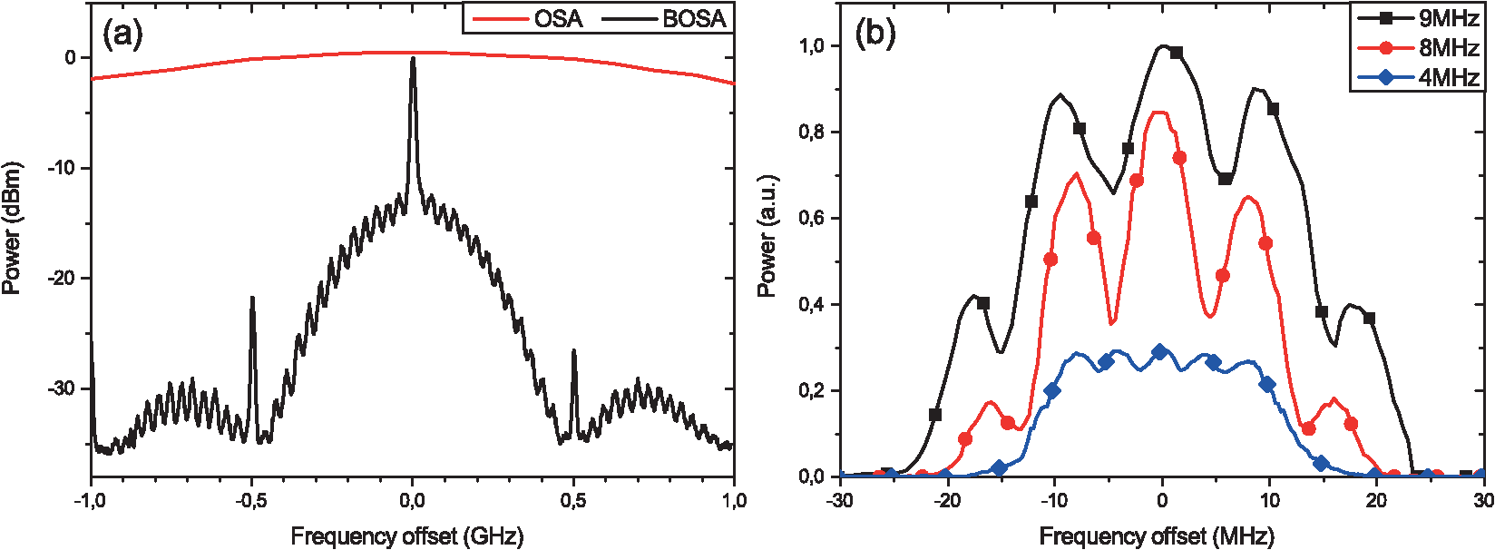 4.2.Quasi-Light-StorageAn all-optical memory is one of the bottlenecks in realizing all-optical information networks since it is needed for optical signal processing, synchronization and buffering of the data.66 In recent years, there were several approaches for the delay and storage of optical signals.67 The easiest method for delaying optical signals is a single-fiber element. The desired delay is chosen in advance and it depends on the fiber length. Additionally, for different delay times a fiber network and a switching matrix must be built. However, the delay time is not completely variable for this approach. Due to these disadvantages, the so called “slow-light” concept which could provide a way out of these problems has been discussed and developed for the last few years.68 Within the slow-light method not the length of the propagating material is changed but the group velocity of the signal. Therefore, different mechanisms like Raman or Brillouin69 scattering can be used. This approach is completely tunable,6 and can be made distortion free,70,71 but show rather low-delay times.34 In order to overcome the disadvantage of the low-delay times, the approach for the storage of optical data called QLS20–22 can be utilized. The main principle of QLS is based on the duality between the time and frequency representation of each signal.20 A pulse in the time domain with the temporal width has a spectral distribution with the bandwidth . If the pulse spectrum is multiplied by equally spaced narrow frequency components with the spacing , basically a frequency comb, the result is a sampled version of the pulse spectrum. The multiplication in the frequency domain leads to a convolution in the time domain, which results in an infinite number of undistorted copies of the signal. The copies have a distance of . With a simple time domain switch, e.g., a modulator, one of the delayed copies can be extracted. For the multiplication of the comb and the spectrum SBS is utilized. Due to the bandwidth of SBS, the different copies are covered with an envelope.20 Therefore, the maximum storage time is defined by the inverse of the SBS bandwidth. This leads to maximum storage times of 100 ns for a SBS bandwidth of 10 MHz in the high-pump power regime.21,22 Exemplarily, the storage of a 4 bit packet with the data sequence of 1101 with the normal SBS bandwidth can be seen in Fig. 10 in the black trace. The results are normalized in amplitude. If the frequency spacing is below the SBS bandwidth, the comb will generate one broadened SBS gain distribution.72 In this case, the QLS acts like a conventional slow-light system and only low-delay times could be achieved. The four wave mixing products generated due to the narrow frequency spacing between the frequency lines can be neglected.34 Fig. 10Quasi-light-storage of a “1101” bit sequence with the standard Brillouin bandwidth (black), the narrowed gain through superposition (red), and in a multistage system (blue). 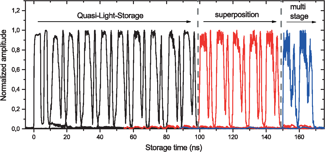 However, the maximum storage time can be enhanced significantly by the SBS gain bandwidth reduction. As can be seen from the red trace in Fig. 10, the storage time can be enhanced up to 140 ns with the superposition of the gain with two losses.73 Higher storage times are limited by the overall gain reduction within this method. For the multistage system, the maximum storage time can be enhanced up to 160 ns. The additional storage time is normalized and represented through the blue trace. Here, the maximum storage time was limited by the number of the stages during the experiment.32 The aperture method for the bandwidth reduction of SBS cannot be applied here, since it adds a numerous amount of noise to the signal. The principle idea of the QLS can also be integrated on an optical chip.74 Thereby, the data is transferred in the frequency domain with a high-dispersive element and then processed with an intensity modulator driven by a train of pulses. Afterward, the signal is transferred back into the time domain with a dispersion compensating element. Finally, an optical switch can be used to extract the desired delayed signal from the generated replicas. 4.3.Frequency Comb ProcessingThe narrowband characteristics of SBS are predestined for the filtering and processing of frequency combs.75 The spectral representation of the pulse trains produced by a mode-locked laser is a frequency comb consisting of comb lines with equal spacing and phase. Especially, femtosecond fiber lasers can produce frequency combs with a very high quality and bandwidth. At the same time, these fiber lasers have a small footprint, are cost effective, and have a center frequency in the range of the C-band of optical telecommunications. Typically, such devices have a span of more than 40 nm and a frequency separation of 80 to 100 MHz between the lines. The output spectrum of the FemtoFErb 1560 can be seen in Fig. 11(a) including a detailed measurement with a BOSA62 in Fig. 11(b). As mentioned in Sec. 1, the frequency separation between the lines is far too narrow for the selection of single tones with standard optical filters. In order to separate individual lines, SBS is needed. Especially, the polarization pulling effect enables the extraction of single lines including the suppression of all out-of-band components. Fig. 11(a) Optical spectrum of a femtosecond fiber laser measured with a conventional OSA and (b) a detailed measurement with a BOSA. 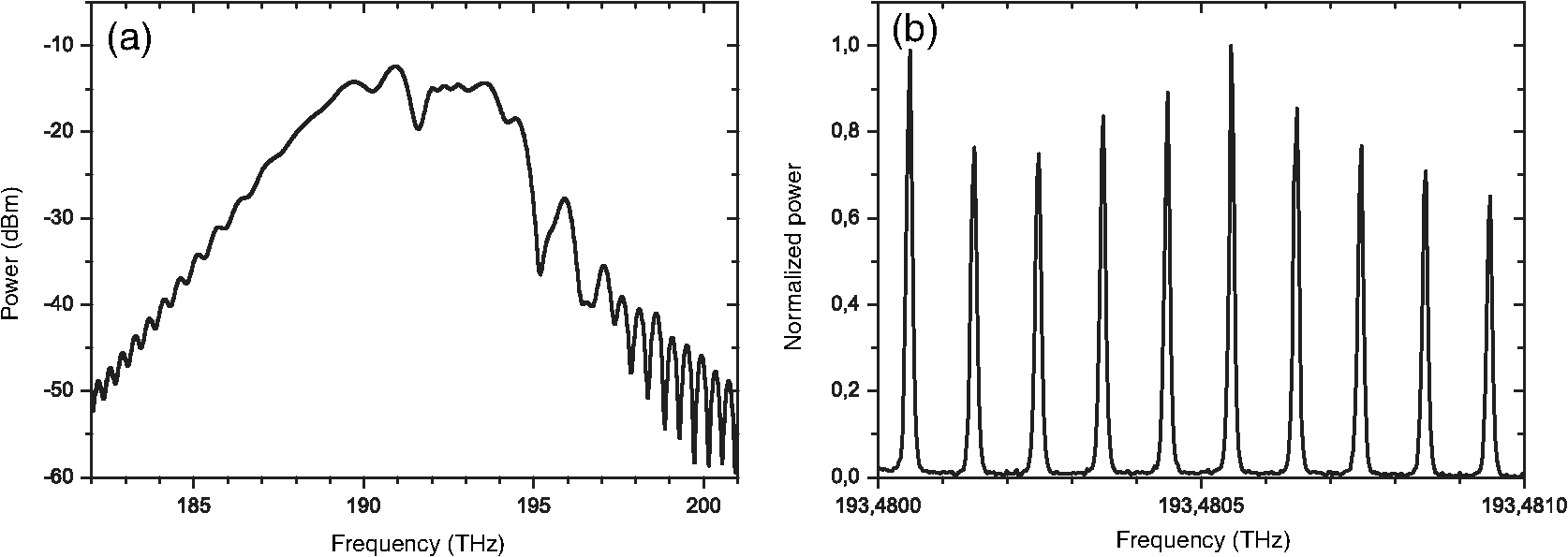 Depending on the number of filtered lines, different applications can be realized. If just one of the comb lines is extracted, as illustrated in Fig. 12(a), it can be used as a narrow linewidth, tunable laser source.76 The gray lines depict the original frequency comb lines, the red line represent the single extracted comb component, and the small black lines represent the suppression of the out-of-band components due to PPA-SBS. With an appropriate modulation of the extracted line, it can be long-term stabilized in the Hz region and additionally fine tuned.76 The coarse tuning is enabled by selecting a different line; thus, the broad bandwidth of the comb and the possibility of nonlinear broadening, in principle, means that a tunability of more than 100 nm could be achieved. Fig. 12(a) Illustration of the extraction of single comb lines out of a frequency comb for a single line laser, (b) mm-wave generation and (c) the creation of a flat rectangular frequency comb (d) and almost ideal sinc-shaped Nyquist pulse generation.  Beyond this, the selection of two lines out of the comb, as displayed in Fig. 12(b), leads to very narrow, stable and tunable millimeter or THz-waves.77,78 Beside potential applications in spectroscopy, radar and metrology, wireless communications is an important field that utilizes high-frequency electromagnetic waves. In the millimeter and THz region of the electromagnetic spectrum, large and up to now unregulated bandwidth is available for wireless communications.79 Generating and processing signals with multi-GHz frequencies are challenging using electrical systems due to the impairments such as electromagnetic interference and large loss at high frequencies. These disadvantages can be overcome by photonic approaches, resulting in stable, high-performance microwave sources and signal processing.80 If two lines of the frequency comb are extracted and heterodyned in an appropriate photomixer, the generated mm- or THz-wave can achieve very high quality. In between, experiments have shown a measured phase noise of at 10 kHz offset and a linewidth of 1 Hz.81 Additionally, due to the broad bandwidth of the comb, the tunability in principle can be over several THz and all lines of the comb are phase-locked. The extraction and further processing of more than two lines can lead to very short, high-quality Nyquist pulses with an almost ideal sinc-shape.82 In order to overcome the bandwidth constraints in optical communication networks and allocate almost all of the available bandwidth, Nyquist pulse transmission can be used.83 Contrary to orthogonal frequency-division multiplexing system, in Nyquist wavelength division multiplexing (N-WDM) systems the pulses are sinc-shaped. Therefore, the spectrum of these signals is perfectly rectangular. This enables the possibility to set the different channels directly next to each other in order to fully allocate the given bandwidth. The challenge for flexible N-WDM systems is the generation of ideally sinc-shaped Nyquist pulses with variable bandwidth and repetition rates. The Fourier representation of a sinc pulse corresponds to a rectangular spectral function, and consequently, a periodic train of sinc pulses corresponds to a rectangular-shaped and phase-locked frequency comb.84 Such combs can be generated by using a single-mode external cavity laser diode and cascading two Mach–Zehnder modulators.85 But the overall bandwidth and number of lines of such a comb are limited due to the frequency range of the modulators. This results in a limited pulse duration and repetition rate of the generated pulses. In order to enhance the bandwidth and repetition rate, multiple carrier frequencies can be extracted out of the given frequency comb by the narrowband SBS filter and subsequently modulated. The extraction of three lines and the generated flat frequency comb is schematically shown in Fig. 12(c). The time domain representation forms an ideal sinc-shaped Nyquist pulse train, as depicted in Fig. 12(d). First experiments have shown flat, rectangular frequency combs with a maximum bandwidth of 260 GHz with 27 equidistant frequency components and a power deviation of only 0.6 dB.86 Additionally, almost ideal sinc-shaped Nyquist pulses with a pulse width of 3.5 ps and a duty cycle of 2.2% have been reported.82 5.ConclusionIn conclusion, we have shown three promising methods to reduce the gain bandwidth of SBS in optical fibers at room temperature, as well as applications in microwave photonics and optical signal processing. The results for a multistage Brillouin system show a reduction of the bandwidth down to 56% of the natural gain bandwidth, limited by the number of stages. Further reduction down to 17% was achieved by the superposition of the gain with two losses. The lowest bandwidth of only 15% was achieved by utilizing a frequency domain aperture. These unique, narrowband properties of SBS enable numerous applications like spectrum analysis, data storage as well as microwave signal generation and processing. We have shown the high-resolution spectroscopy of optical and microwave signals that reveals previously concealed details. The overall storage time of optical data packets with quasilight storage could be enhanced by 60% through the bandwidth narrowing, and SBS was utilized for the generation of mm- and THz-waves with a narrow linewidth of 1 Hz and low-phase noise of at an offset of 10 kHz from the carrier, as well as the generation of ideal sinc-shaped Nyquist pulses. AcknowledgmentsThe authors would like to acknowledge the fruitful discussions and support from A. Zadok from Bar-Ilan University in Israel, N. Wenzel and J. Klinger from the Hochschule für Telekommunikation in Leipzig, as well as H. Al-Taiy from the Technische Universität Braunschweig. ReferencesA. J. Seeds and K. J. Williams,
“Microwave photonics,”
J. Lightwave Technol., 24
(12), 4628
–4641
(2006). http://dx.doi.org/10.1109/JLT.2006.885787 JLTEDG 0733-8724 Google Scholar
J. Capmany and D. Novak,
“Microwave photonics combines two worlds,”
Nat. Photonics, 1
(6), 319
–330
(2007). http://dx.doi.org/10.1038/nphoton.2007.89 NPAHBY 1749-4885 Google Scholar
J. Yao,
“Microwave photonics,”
J. Lightwave Technol., 27
(3), 314
–335
(2009). http://dx.doi.org/10.1109/JLT.2008.2009551 JLTEDG 0733-8724 Google Scholar
G. P. Agrawal, Nonlinear Fiber Optics, Academic Press, Amsterdam
(2007). Google Scholar
A. Loayssa and F. J. Lahoz,
“Broad-band RF photonic phase shifter based on stimulated Brillouin scattering and single-sideband modulation,”
IEEE Photonics Technol. Lett., 18
(1), 208
–210
(2006). http://dx.doi.org/10.1109/LPT.2005.861307 IPTLEL 1041-1135 Google Scholar
Y. Okawachi et al.,
“Tunable all-optical delays via Brillouin slow light in an optical fiber,”
Phys. Rev. Lett., 94
(15), 153902
(2005). http://dx.doi.org/10.1103/PhysRevLett.94.153902 PRLTAO 0031-9007 Google Scholar
T. Schneider, M. Junker and K. U. Lauterbach,
“Time delay enhancement in stimulated-Brillouin-scattering-based slow-light systems,”
Opt. Lett., 32
(3), 220
–222
(2007). http://dx.doi.org/10.1364/OL.32.000220 OPLEDP 0146-9592 Google Scholar
B. Vidal, M. Piqueras and J. Mart,
“Tunable and reconfigurable photonic microwave filter based on stimulated Brillouin scattering,”
Opt. Lett., 32
(1), 23
–25
(2007). http://dx.doi.org/10.1364/OL.32.000023 OPLEDP 0146-9592 Google Scholar
Y. Stern et al.,
“Tunable sharp and highly selective microwave-photonic band-pass filters based on stimulated Brillouin scattering,”
Photonics Res., 2
(4), B18
–B25
(2014). http://dx.doi.org/10.1364/PRJ.2.000B18 Google Scholar
J. Sancho et al.,
“Tunable and reconfigurable multi-tap microwave photonic filter based on dynamic Brillouin gratings in fibers,”
Opt. Express, 20
(6), 6157
–6162
(2012). http://dx.doi.org/10.1364/OE.20.006157 OPEXFF 1094-4087 Google Scholar
L. Brillouin,
“Diffusion de la lumière et des rayons X par un corps transparent homogène. Influence de l’agitation thermique,”
Ann. Phys. (Paris), 17 88
–122
(1922). ANPHAJ 0003-4169 Google Scholar
E. Ippen and R. Stolen,
“Stimulated Brillouin scattering in optical fibers,”
Appl. Phys. Lett., 21
(11), 539
–541
(1972). http://dx.doi.org/10.1063/1.1654249 APPLAB 0003-6951 Google Scholar
T. Schneider, Nonlinear Optics in Telecommunications, Springer Science & Business Media, Berlin
(2004). Google Scholar
R. W. Boyd, Nonlinear Optics, Academic Press, Amsterdam
(2003). Google Scholar
T. Tanemura, Y. Takushima and K. Kikuchi,
“Narrowband optical filter, with a variable transmission spectrum, using stimulated Brillouin scattering in optical fiber,”
Opt. Lett., 27
(17), 1552
–1554
(2002). http://dx.doi.org/10.1364/OL.27.001552 OPLEDP 0146-9592 Google Scholar
M. G. Herráez, K. Y. Song and L. Thévenaz,
“Arbitrary-bandwidth Brillouin slow light in optical fibers,”
Opt. Express, 14
(4), 1395
–1400
(2006). http://dx.doi.org/10.1364/OE.14.001395 OPEXFF 1094-4087 Google Scholar
Z. Lu, Y. Dong and Q. Li,
“Slow light in multi-line Brillouin gain spectrum,”
Opt. Express, 15
(4), 1871
–1877
(2007). http://dx.doi.org/10.1364/OE.15.001871 OPEXFF 1094-4087 Google Scholar
T. Schneider et al.,
“Adapting Brillouin spectrum for slow light delays,”
Electron. Lett., 43
(12), 682
–683
(2007). http://dx.doi.org/10.1049/el:20070313 Google Scholar
T. Schneider,
“Wavelength and line width measurement of optical sources with femtometre resolution,”
Electron. Lett., 41
(22), 1234
–1235
(2005). http://dx.doi.org/10.1049/el:20053204 Google Scholar
S. Preußler et al.,
“Quasi-light-storage based on time-frequency coherence,”
Opt. Express, 17
(18), 15790
–15798
(2009). http://dx.doi.org/10.1364/OE.17.015790 OPEXFF 1094-4087 Google Scholar
T. Schneider, K. Jamshidi and S. Preußler,
“Quasi-light storage: a method for the tunable storage of optical packets with a potential delay-bandwidth product of several thousand bits,”
J. Lightwave Technol., 28
(17), 2586
–2592
(2010). http://dx.doi.org/10.1109/JLT.2010.2056355 JLTEDG 0733-8724 Google Scholar
K. Jamshidi et al.,
“A review to the all-optical quasi-light storage,”
IEEE J. Sel. Top. Quantum Electron., 18
(2), 884
–890
(2012). http://dx.doi.org/10.1109/JSTQE.2011.2134836 IJSQEN 1077-260X Google Scholar
P. Bayvel and P. Radmore,
“Solutions of the SBS equations in single mode optical fibres and implications for fibre transmission systems,”
Electron. Lett., 26
(7), 434
–436
(1990). http://dx.doi.org/10.1049/el:19900282 Google Scholar
A. L. Gaeta and R. W. Boyd,
“Stochastic dynamics of stimulated Brillouin scattering in an optical fiber,”
Phys. Rev. A, 44
(5), 3205
(1991). http://dx.doi.org/10.1103/PhysRevA.44.3205 Google Scholar
M. Nikles, L. Thévenaz and P. Robert,
“Brillouin gain spectrum characterization in singlemode optical fibers,”
J. Lightwave Technol., 15
(10), 1842
–1851
(1997). http://dx.doi.org/10.1109/50.633570 JLTEDG 0733-8724 Google Scholar
C. Lee and S. Chi,
“Measurement of stimulated-Brillouin-scattering threshold for various types of fibers using Brillouin optical-time-domain reflectometer,”
IEEE Photonics Technol. Lett., 12
(6), 672
–674
(2000). http://dx.doi.org/10.1109/68.849080 IPTLEL 1041-1135 Google Scholar
L. Xing et al.,
“Storage capacity of slow-light tunable optical buffers based on fiber Brillouin amplifiers for real signal bit streams,”
Opt. Express, 15
(16), 10189
–10195
(2007). http://dx.doi.org/10.1364/OE.15.010189 OPEXFF 1094-4087 Google Scholar
A. Yeniay, J. M. Delavaux and J. Toulouse,
“Spontaneous and stimulated Brillouin scattering gain spectra in optical fibers,”
J. Lightwave Technol., 20
(8), 1425
(2002). http://dx.doi.org/10.1109/JLT.2002.800291 JLTEDG 0733-8724 Google Scholar
J. H. Lee et al.,
“Experimental comparison of a Kerr nonlinearity figure of merit including the stimulated Brillouin scattering threshold for state-of-the-art nonlinear optical fibers,”
Opt. Lett., 30
(13), 1698
–1700
(2005). http://dx.doi.org/10.1364/OL.30.001698 OPLEDP 0146-9592 Google Scholar
R. Esman and K. Williams,
“Brillouin scattering: beyond threshold,”
in Optical Fiber Communications Conf.,
227
–228
(1996). Google Scholar
A. Fellay et al.,
“Brillouin based temperature sensing in optical fibres down to 1 K,”
in Optical Fiber Sensors Conf. Technical Digest,
301
–304
(2002). Google Scholar
S. Preußler and T. Schneider,
“Bandwidth reduction in a multistage Brillouin system,”
Opt. Lett., 37
(19), 4122
–4124
(2012). http://dx.doi.org/10.1364/OL.37.004122 OPLEDP 0146-9592 Google Scholar
S. Preußler et al.,
“Brillouin scattering gain bandwidth reduction down to 3.4 MHz,”
Opt. Express, 19
(9), 8565
–8570
(2011). http://dx.doi.org/10.1364/OE.19.008565 OPEXFF 1094-4087 Google Scholar
T. Schneider,
“Time delay limits of stimulated-Brillouin-scattering-based slow light systems,”
Opt. Lett., 33
(13), 1398
–1400
(2008). http://dx.doi.org/10.1364/OL.33.001398 OPLEDP 0146-9592 Google Scholar
A. Wiatrek et al.,
“Frequency domain aperture for the gain bandwidth reduction of stimulated Brillouin scattering,”
Opt. Lett., 37
(5), 930
–932
(2012). http://dx.doi.org/10.1364/OL.37.000930 OPLEDP 0146-9592 Google Scholar
J. Capmany, B. Ortega and D. Pastor,
“A tutorial on microwave photonic filters,”
J. Lightwave Technol., 24
(1), 201
–229
(2006). http://dx.doi.org/10.1109/JLT.2005.860478 JLTEDG 0733-8724 Google Scholar
A. Mokhtari et al.,
“Fully-tunable microwave photonic filter with complex coefficients using tunable delay lines based on frequency-time conversions,”
Opt. Express, 20
(20), 22728
–22734
(2012). http://dx.doi.org/10.1364/OE.20.022728 OPEXFF 1094-4087 Google Scholar
A. Mokhtari et al.,
“Tunable microwave-photonic filter using frequency-to-time mapping-based delay lines,”
Opt. Express, 21
(18), 21702
–21707
(2013). http://dx.doi.org/10.1364/OE.21.021702 OPEXFF 1094-4087 Google Scholar
W. W. Zhang and R. A. Minasian,
“Widely tunable single-passband microwave photonic filter based on stimulated Brillouin scattering,”
IEEE Photonics Technol. Lett., 23
(23), 1775
–1777
(2011). http://dx.doi.org/10.1109/LPT.2011.2169242 IPTLEL 1041-1135 Google Scholar
B. Vidal, T. Mengual and J. Marti,
“Photonic microwave filter with single bandpass response based on Brillouin processing and SSB-SC,”
in Int. Topical Meeting on Microwave Photonics,
(2009). Google Scholar
Y. Xiao et al.,
“An ultrawide tunable range single passband microwave photonic filter based on stimulated Brillouin scattering,”
Opt. Express, 21
(3), 2718
–2726
(2013). http://dx.doi.org/10.1364/OE.21.002718 OPEXFF 1094-4087 Google Scholar
W. Wang et al.,
“Widely tunable single bandpass microwave photonic filter based on Brillouin-assisted optical carrier recovery,”
Opt. Express, 22
(24), 29304
–29313
(2014). http://dx.doi.org/10.1364/OE.22.029304 OPEXFF 1094-4087 Google Scholar
R. Tao et al.,
“Widely tunable single bandpass microwave photonic filter based on phase modulation and stimulated Brillouin scattering,”
IEEE Photonics Technol. Lett., 24
(13), 1097
–1099
(2012). http://dx.doi.org/10.1109/LPT.2012.2195486 IPTLEL 1041-1135 Google Scholar
W. Zhang and R. Minasian,
“Ultrawide tunable microwave photonic notch filter based on stimulated brillouin scattering,”
IEEE Photonics Technol. Lett., 24
(14), 1182
–1184
(2012). http://dx.doi.org/10.1109/LPT.2012.2198638 IPTLEL 1041-1135 Google Scholar
W. Zhang and R. Minasian,
“Switchable and tunable microwave photonic Brillouin-based filter,”
IEEE Photonics J., 4
(5), 1443
–1455
(2012). http://dx.doi.org/10.1109/JPHOT.2012.2209114 Google Scholar
X. Han et al.,
“Filtering properties of the tunable microwave photonic filter with stimulated Brillouin scattering,”
Opt. Eng., 53
(6), 066110
(2014). http://dx.doi.org/10.1117/1.OE.53.6.066110 Google Scholar
X. Han et al.,
“Bandwidth tunability of stimulated Brillouin scattering based microwave photonic filter,”
in 2014 Int. Topical Meeting on Microwave Photonics (MWP) and the 2014 9th Asia-Pacific Microwave Photonics Conference (APMP),
257
–260
(2014). Google Scholar
W. T. Wang et al.,
“Microwave photonic filter with complex coefficient based on optical carrier phase shift utilizing two stimulated Brillouin scattering pumps,”
IEEE Photonics J., 7
(1), 5500208
(2015). http://dx.doi.org/10.1109/JPHOT.2015.2390150 Google Scholar
D. Zhou et al.,
“Reconfigurable pass-band microwave photonic filter using frequency combs and stimulated Brillouin scattering,”
in Asia Communications and Photonics Conf.,
(2014). Google Scholar
Y. Stern et al.,
“Frequency-selective filtering and analysis of radio-over-fiber using stimulated Brillouin scattering,”
in 2013 Int. Topical Meeting on Microwave Photonics (MWP),
146
–149
(2013). Google Scholar
W. Li, L. X. Wang and N. H. Zhu,
“All-optical microwave photonic single-passband filter based on polarization control through stimulated Brillouin scattering,”
IEEE Photonics J., 5
(4), 5501411
(2013). http://dx.doi.org/10.1109/JPHOT.2013.2271716 Google Scholar
L. Yi et al.,
“Ideal rectangular microwave photonic filter with high selectivity based on stimulated Brillouin scattering,”
in Optical Fiber Communication Conf.,
(2015). Google Scholar
S. Hu et al.,
“Ultraflat widely tuned single bandpass filter based on stimulated Brillouin scattering,”
IEEE Photonics Technol. Lett., 26
(14), 1466
–1469
(2014). http://dx.doi.org/10.1109/LPT.2014.2322099 IPTLEL 1041-1135 Google Scholar
R. Pant et al.,
“On-chip stimulated Brillouin scattering for microwave signal processing and generation,”
Laser Photonics Rev., 8
(5), 653
–666
(2014). http://dx.doi.org/10.1002/lpor.201300154 Google Scholar
A. Byrnes et al.,
“Photonic chip based tunable and reconfigurable narrowband microwave photonic filter using stimulated Brillouin scattering,”
Opt. Express, 20
(17), 18836
–18845
(2012). http://dx.doi.org/10.1364/OE.20.018836 OPEXFF 1094-4087 Google Scholar
D. Marpaung et al.,
“Low-power, chip-based stimulated Brillouin scattering microwave photonic filter with ultrahigh selectivity,”
Optica, 2
(2), 76
–83
(2015). http://dx.doi.org/10.1364/OPTICA.2.000076 Google Scholar
B. Morrison et al.,
“Tunable microwave photonic notch filter using on-chip stimulated Brillouin scattering,”
Opt. Commun., 313 85
–89
(2014). http://dx.doi.org/10.1016/j.optcom.2013.09.065 OPCOB8 0030-4018 Google Scholar
J. Subias Domingo et al.,
“Very high resolution optical spectrometry by stimulated Brillouin scattering,”
IEEE Photonics Technol. Lett., 17
(4), 855
–857
(2005). http://dx.doi.org/10.1109/LPT.2005.843946 IPTLEL 1041-1135 Google Scholar
S. Preussler et al.,
“Enhancement of spectral resolution and optical rejection ratio of Brillouin optical spectral analysis using polarization pulling,”
Opt. Express, 20
(13), 14734
–14745
(2012). http://dx.doi.org/10.1364/OE.20.014734 OPEXFF 1094-4087 Google Scholar
A. Zadok et al.,
“Vector analysis of stimulated Brillouin scattering amplification in standard single-mode fibers,”
Opt. Express, 16
(26), 21692
–21707
(2008). http://dx.doi.org/10.1364/OE.16.021692 OPEXFF 1094-4087 Google Scholar
A. Wise, M. Tur and A. Zadok,
“Sharp tunable optical filters based on the polarization attributes of stimulated Brillouin scattering,”
Opt. Express, 19
(22), 21945
–21955
(2011). http://dx.doi.org/10.1364/OE.19.021945 OPEXFF 1094-4087 Google Scholar
S. Treff, S. Preussler and T. Schneider,
“Measuring the spectra of advanced optical signals with an extension of an electrical network analyzer,”
in Optical Fiber Communication Conf. and Exposition and the National Fiber Optic Engineers Conference (OFC/NFOEC),
(2013). Google Scholar
A. Wiatrek et al.,
“Frequency domain aperture for ultra-high resolution Brillouin based spectroscopy,”
in CLEO: Applications and Technology,
(2012). Google Scholar
S. Preussler et al.,
“Increasing the resolution of optical spectrometers for the measurement of advanced optical communication signals,”
in European Conf. and Exhibition on Optical Communication 38,
(2012). Google Scholar
S. Preussler et al.,
“Ultrahigh-resolution spectroscopy based on the bandwidth reduction of stimulated Brillouin scattering,”
IEEE Photonics Technol. Lett., 23
(16), 1118
–1120
(2011). http://dx.doi.org/10.1109/LPT.2011.2157338 IPTLEL 1041-1135 Google Scholar
T. F. Krauss,
“Why do we need slow light?,”
Nat. Photonics, 2
(8), 448
–450
(2008). http://dx.doi.org/10.1038/nphoton.2008.139 NPAHBY 1749-4885 Google Scholar
E. F. Burmeister, D. J. Blumenthal and J. E. Bowers,
“A comparison of optical buffering technologies,”
Opt. Switching Networking, 5
(1), 10
–18
(2008). http://dx.doi.org/10.1016/j.osn.2007.07.001 Google Scholar
R. S. Tucker, P. C. Ku and C. J. Chang-Hasnain,
“Slow-light optical buffers: capabilities and fundamental limitations,”
J. Lightwave Technol., 23
(12), 4046
(2005). http://dx.doi.org/10.1109/JLT.2005.853125 JLTEDG 0733-8724 Google Scholar
K. Y. Song, M. G. Herráez and L. Thévenaz,
“Observation of pulse delaying and advancement in optical fibers using stimulated Brillouin scattering,”
Opt. Express, 13
(1), 82
–88
(2005). http://dx.doi.org/10.1364/OPEX.13.000082 OPEXFF 1094-4087 Google Scholar
A. Wiatrek et al.,
“Nonlinear Brillouin based slow-light system for almost distortion-free pulse delay,”
J. Opt. Soc. Am. B, 27
(3), 544
–549
(2010). http://dx.doi.org/10.1364/JOSAB.27.000544 JOBPDE 0740-3224 Google Scholar
A. Wiatrek et al.,
“Pulse broadening cancellation in cascaded slow-light delays,”
Opt. Express, 17
(9), 7586
–7591
(2009). http://dx.doi.org/10.1364/OE.17.007586 OPEXFF 1094-4087 Google Scholar
R. Henker et al.,
“Group velocity dispersion reduction in fibre-based slow light systems via stimulated Brillouin scattering,”
Electron. Lett., 44
(20), 1185
–1186
(2008). http://dx.doi.org/10.1049/el:20082007 ELLEAK 0013-5194 Google Scholar
S. Preussler et al.,
“Quasi-light-storage enhancement by reducing the Brillouin gain bandwidth,”
Appl. Opt., 50
(22), 4252
–4256
(2011). http://dx.doi.org/10.1364/AO.50.004252 Google Scholar
K. Jamshidi et al.,
“Widely tunable optical delay generator,”
Opt. Lett., 35
(21), 3592
–3594
(2010). http://dx.doi.org/10.1364/OL.35.003592 OPLEDP 0146-9592 Google Scholar
T. Schneider,
“Fiber-laser frequency combs for the generation of tunable single-frequency laser lines, mm-and THz-waves and sinc-shaped Nyquist pulses,”
Proc. SPIE, 9378 937822
(2015). http://dx.doi.org/10.1117/12.2086828 PSISDG 0277-786X Google Scholar
H. Al-Taiy et al.,
“Ultra-narrow linewidth, stable and tunable laser source for optical communication systems and spectroscopy,”
Opt. Lett., 39
(20), 5826
–5829
(2014). http://dx.doi.org/10.1364/OL.39.005826 OPLEDP 0146-9592 Google Scholar
S. Preußler et al.,
“Generation of ultra-narrow, stable and tunable millimeter- and terahertz-waves with very low phase noise,”
Opt. Express, 21
(20), 23950
–23962
(2013). http://dx.doi.org/10.1364/OE.21.023950 OPEXFF 1094-4087 Google Scholar
S. Preussler et al.,
“Tunable generation of ultra-narrow linewidth millimeter and THz-waves and their modulation at 40 Gbd,”
in Int. Topical Meeting on Microwave Photonics (MWP),
119
–122
(2013). Google Scholar
T. Schneider et al.,
“Link budget analysis for terahertz fixed wireless links,”
IEEE Trans. Terahertz Sci. Technol., 2
(2), 250
–256
(2012). http://dx.doi.org/10.1109/TTHZ.2011.2182118 Google Scholar
T. Schneider,
“Ultrahigh-bitrate wireless data communications via THz-links; possibilities and challenges,”
J. Infrared Millimeter Terahertz Waves, 36
(2), 159
–179
(2015). http://dx.doi.org/10.1007/s10762-014-0100-1 Google Scholar
H. Al-Taiy et al.,
“Generation of highly stable millimeter waves with low phase noise and narrow linewidth,”
IEEE Photonics Technol. Lett., 27
(15), 1613
–1616
(2015). http://dx.doi.org/10.1109/LPT.2015.2432464 IPTLEL 1041-1135 Google Scholar
S. Preussler, N. Wenzel and T. Schneider,
“Flexible Nyquist pulse sequence generation with variable bandwidth and repetition rate,”
IEEE Photonics J., 6
(4), 1
–8
(2014). http://dx.doi.org/10.1109/JPHOT.2014.2331240 Google Scholar
G. Bosco et al.,
“On the performance of Nyquist-WDM terabit superchannels based on PM-BPSK, PM-QPSK, PM-8QAM or PM-16QAM subcarriers,”
J. Lightwave Technol., 29
(1), 53
–61
(2011). http://dx.doi.org/10.1109/JLT.2010.2091254 JLTEDG 0733-8724 Google Scholar
M. A. Soto et al.,
“Optical sinc-shaped Nyquist pulses of exceptional quality,”
Nat. Commun., 4 2898
(2013). http://dx.doi.org/10.1038/ncomms3898 NCAOBW 2041-1723 Google Scholar
M. A. Soto et al.,
“Generation of Nyquist sinc pulses using intensity modulators,”
(2013). Google Scholar
S. Preussler, N. Wenzel and T. Schneider,
“Flat, rectangular frequency comb generation with tunable bandwidth and frequency spacing,”
Opt. Lett., 39
(6), 1637
–1640
(2014). http://dx.doi.org/10.1364/OL.39.001637 OPLEDP 0146-9592 Google Scholar
BiographyStefan Preussler received his BEng degree in 2007 and the Dipl.-Ing. (FH) degree in 2008 in the field of electrical engineering from the Hochschule für Telekommunikation in Leipzig, Germany. Currently, he is working toward his PhD at the Institut für Hochfrequenztechnik at the Technische Universität in Braunschweig. His research interests include nonlinear fiber optics and particularly stimulated Brillouin scattering including applications like data storage, spectroscopy as well as mm- and THz-wave generation and communication. Thomas Schneider received his diploma from the Humboldt Universität zu Berlin in 1995 and his PhD from the Technische Universität Cottbus in 2000. From 2000 to 2014, he was the head of the Institut für Hochfrequenztechnik at the Hochschule für Telekommunikation in Leipzig. Since 2014, he has been the head of the Terahertz group at the Technische Universität Braunschweig. His current research interests include microwave- and Terahertz-photonics, nonlinear optics, and optical communications. |