
|
|
1.IntroductionOptical fibers have seen increasing use as sensing elements for strain, stress, temperature, and refractive index measurements in a wide variety of engineering applications. A more recent application of fiber sensors is to determine angle and position information used for three-dimensional (3-D) shape sensing. Due to its compact size and ability to conform to relatively complex shapes, optical fiber can be easily fixed along an object of interest to mirror its orientation. Multiple strain sensors can then be integrated together to form a single sensing probe aligned to the changing contour along the object. By using a multicore fiber or a multifiber bundle packaging method, three or more strain sensors can be packaged in parallel together as one sensing element to measure strain information in three dimensions, data that can ultimately be used to find the angle and position information necessary for 3-D shape sensing. Different fiber distributed strain sensors have been proposed and commercialized to reach this engineering goal. The two main research areas undergirding this technology are fiber Bragg gratings (FBGs) and coherent optical frequency-domain reflectometry (C-OFDR). Both methods use differing fundamental physics to reach the same goal: distributed strain sensing along an optical fiber. An FBG is a wavelength-based fiber sensor.1,2 Periodic reflectors are inscribed along a single-mode fiber by UV laser to form a wavelength-specific dielectric mirror that reflects a certain wavelength and transmits the rest. Multiple FBGs can be integrated along one sensing probe using wavelength multiplexing to achieve distributed strain measurements. Miller et al. have proposed several FBG-based structures used to resolve the spatial angle information using multiple FBGs, which include multicore fibers3,4 and three-fiber bundles5 as two-axis fiber inclinometers. More recently, researchers have demonstrated using a femtosecond laser to directly inscribe FBG waveguide structures into a single coreless fiber6 and standard single-mode fiber7 for 3-D shape sensing applications. C-OFDR8–15 is an alternative, state-of-the-art distributed sensing technology. By sweeping the optical frequency with a tunable laser, the Rayleigh backscatter profile along an optical fiber can be measured, which correlates to strain along the fiber under test. This interferometric measurement is capable of maintaining a terahertz-level detection bandwidth with high spatial resolution. Using three or more probes, C-OFDR has successfully demonstrated its ability to deliver 3-D shape sensing using both the multicore fiber16–18 and multiple fiber packing methods.19 Recently, the use of terahertz FBG (THz FBG), an extension of C-OFDR interrogation, has been demonstrated.20,21 A high-power femtosecond laser is employed to inscribe ultraweak periodic reflectors (less than ) within the core of a standard single-mode optical fiber, providing distributed interferometric strain measurements along the fiber under test and allowing the system to achieve enhanced sensitivity compared with traditional Rayleigh scattering-based (less than ) C-OFDR techniques. By combining three or more of these THz FBG sensors into a single-fiber sensor bundle, the system is able to determine the spatial angle information necessary to act as a two-axis optical fiber inclinometer, an important step toward 3-D shape sensing. This paper reports a terahertz fiber grating-based two-axis optical fiber inclinometer fabricated using ultraweak reflection arrays (). Three identical THz FBGs were aligned and packaged as a single fiber bundle. The differing strain distributions across the three THz FBGs within the sensing probe were measured and used to determine the spatial angle information along the fiber bundle. The inclinometer was tested at eight azimuthal angles (from 0 to 315 deg). The standard deviation of the greatest inclination angle error was 0.048 deg and the inclination angle stability was 0.030 deg. No cross-talk was found between the ultraweak reflection arrays. 2.Mechanism of OperationIn order to experimentally investigate the terahertz grating-based inclinometer concept, a 30-mm-long inclinometer was constructed. Three identical THz FBGs were fabricated with intact buffer coatings using single-mode fiber (SMF-28, Corning) and a Ti:Sapphire fs laser (Coherent, Inc.) micromachining system.22–26 Each sensing array contained 41 ultraweak reflectors (approximately ) with a pitch length of 1 mm. To bind the modified fibers into a three-fiber bundle, the three SMF fibers with THz FBG arrays were secured equidistant to one another, as shown in Fig. 2(a). The three modified fibers were aligned using reference marks beyond the length of the sensing arrays. Two 40-mm heat melt tubes (EVA) and a 90-mm heat shrink tube were placed outside the aligned sensing arrays, as illustrated in Fig. 1(a). Hot air () was blown from away and swept across the length of the bundle at a speed of . After subsequent cooling, the three THz FBG sensing arrays were firmly fixed in place, as shown in Fig. 1(b). Fig. 1Three-core fiber inclinometer bundle packaging and assembling: (a) before heating, (b) after heating, and (c) assembling the fiber inclinometer.  To assemble the inclinometer, one end of the packaged bundle was positioned using a screwed ferrule into the center of a 360-deg rotational mount (Newport Inc.) along the axis to give azimuthal rotation control, as illustrated in Fig. 1(b). The other end was affixed to a micrometer-level stage that could be moved vertically in the direction, enabling inclination angle control. To conduct the inclination measurement experiment, three THz FBG sensing arrays were cascaded inline, as shown in Fig. 2, and interrogated via C-OFDR.27–29 For each sensing array, a 10-mm time-domain moving filter was applied to measure the distributed strain along the sensor; in total, seven strain measurements at 5-mm steps were extracted. The three strain sensing points at the same position along the inclinometer bundle then form a single sensing element; in total, seven sensing elements along the 30-mm sensor were used. Each sensing element contains 3-D strain information, which can be used to calculate the spatial position in the 3-D Cartesian coordinate system with Frenet–Serret equations. 16 The azimuthal angle was defined as the sensor rotation along the axis. As the sensor was deflected toward the direction, the inclination angle at a certain azimuthal angle , as shown in Fig. 3(b), was defined as the acute angle between the axis and the line passing through the sixth and seventh sensing elements. Fig. 2Schematic of cascaded THz FBG sensors: (a) the time-domain interrogation signal of three identical THz FBG sensing arrays, (b) the details of sensing array 1, and (c) the packaged inclinometer bundle.  Fig. 3Schematic of the measured inclination angle: (a) 3-D representation, and (b) 2-D representation (project to plane). 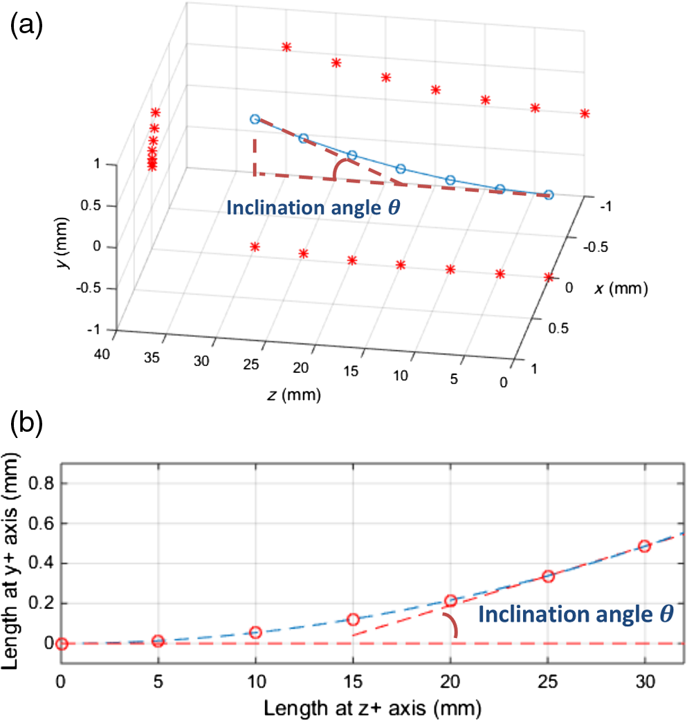 In order to account for packaging inconsistencies such as sensing array misalignment or heat shrink tube nonuniformity, calibration must be performed. First the cross-plane of each sensing element and the relative positions of the three strain sensing points were calibrated. As illustrated in Fig. 4(d), the bundle was bent toward three different azimuthal angles , , and , where sensing arrays #1, #2, and #3 were each positioned on top, respectively. The differing strain distributions for the seven sensing points were then measured along each sensing array. For each sensing element, a two-dimensional (2-D) cross-plane was extracted to calculate the relative position of the three strain sensing points. At each sensing element, the balanced boundary condition can be expressed as where is the strain measurement with the ’th sensing array on top (at azimuthal angle ) for the ’th sensing array and is the related length of the lever arm. It is assumed that the bending occurs across the center of the sensor at origin (0,0) in the 2-D plane. The line perpendicular to the bending direction and passing the origin (0,0), can be expressed as where is the slope of the line with the ’th sensing array on top. At a certain sensing element cross-plane, the relative position of the ’th sensing array on top at the ’th sensing array can be expressed as (, ). The related length of lever arm shown in Figs. 4(a)–4(c) can be expressed as The initial condition is defined where the relative distance between the sensing points along sensing array #1 to the axis is normalized to 1. The relative positions of the three sensing points for each sensing element cross-plane were then solved, as shown in Fig. 5. These coefficients were converted to polar form and applied to solve the Frenet–Serret equations.Fig. 4Calibrate the relative position: (a)–(c) the cross-plane illustration of bending with sensing array #1, #2, and #3 on top, respectively, and (d) schematic of inclination bending. 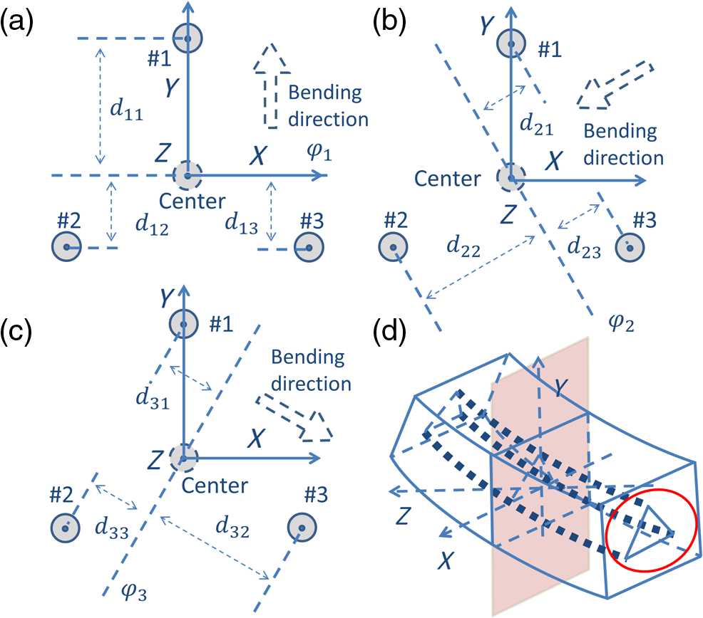 Fig. 5Calibrating the relative position: (a) with sensing array #1 on top, the strain measurement result along the three sensing arrays, and (b) the solved relative position on the first sensing element cross-plane. 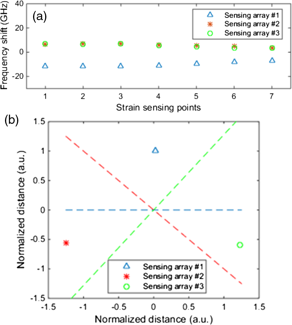 Second, the absolute radius can be calibrated based on the assumption that all seven strain sensing points along the sensing array #1 share the same distance to the center of the inclinometer bundle. Based on the first calibration results, another radius coefficient is set to match the calculated position and the absolute deflection by the -directional stage at each azimuthal angle. 3.Experimental Results and DiscussionsTo investigate the utility of the fiber inclinometer, inclination angles from 0 to 1.7 deg with a step of 0.085 deg were investigated for all eight azimuthal angles (0, 45, 90, 135, 180, 225, 270, and 315 deg). Some of the representative measurement data are plotted in Fig. 6. The calibration coefficients were implemented before inclination testing. The inclination test results at azimuthal angles 0 and 270 deg are shown in Figs. 6(b) and 6(c). Similar results were found with other azimuthal angles. The largest error standard deviation was 0.048 deg. Fig. 6Two-axis inclination measurement results: (a) measured inclination angles , 0.767, and 1.70 deg, respectively, at eight differing azimuthal angles () (45 deg apart from 0 to 315 deg), (b) measured inclination angle against calculated angle at , and (c) measured inclination angle against calculated angle at . 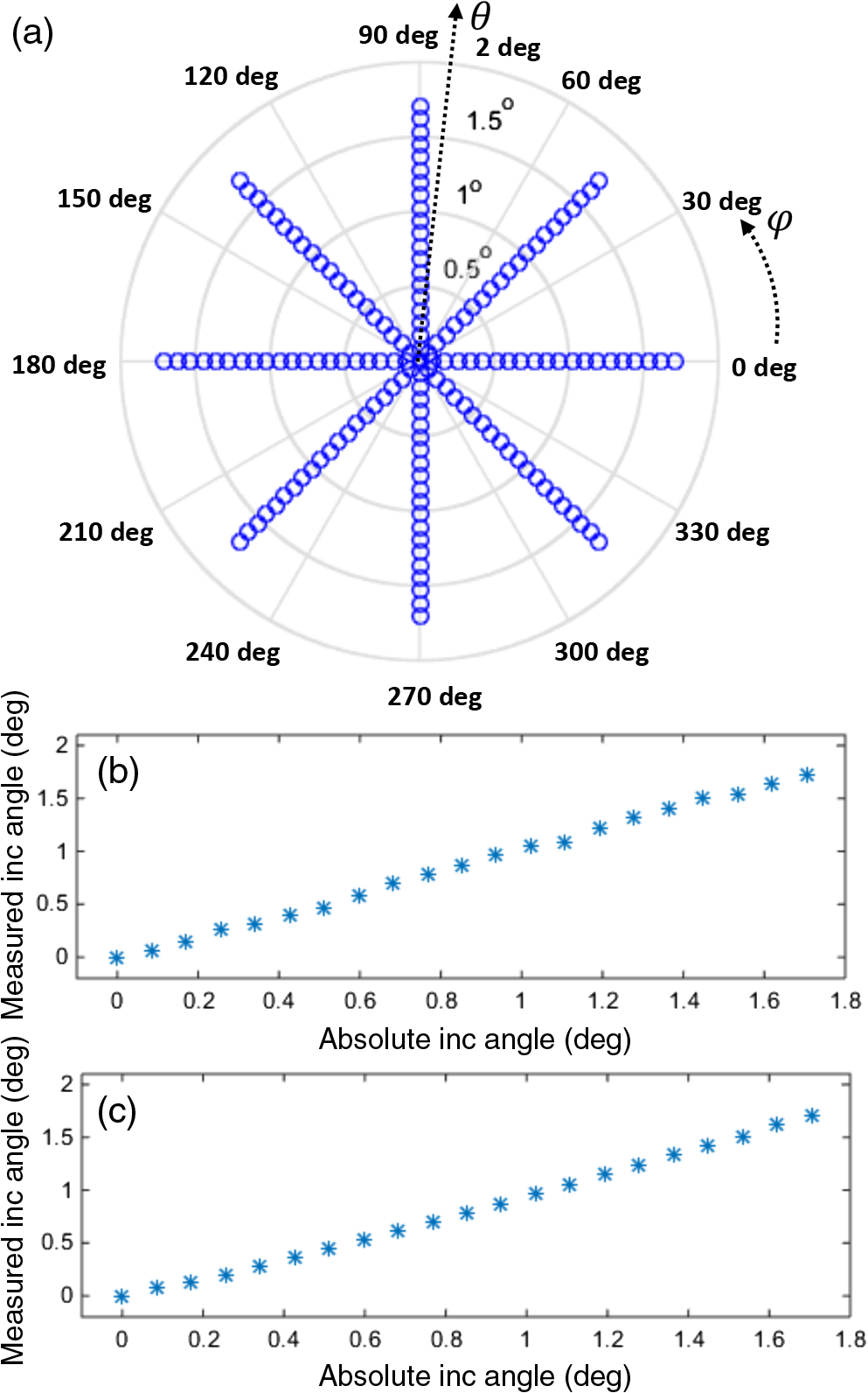 The stability test of the proposed inclinometer was conducted with a fixed 0-deg azimuthal angle and 0-deg inclination angle. In total, 250 sets of tests were repeated to measure this initial inclination angle. The standard deviation of the measured angle was 0.030 deg, indicating a good repeatability for this device. The maximum inclination measurement range was 2.5 deg with steps of 0.085 deg and the error standard deviation was 0.036 deg. In these tests, the inclination measurement range was limited by the maximum frequency shift within one period of the implemented THz FBG, which is 100 GHz for a 1-mm pitch length. 4.ConclusionsTo conclude, this paper reports a new two-axis optical fiber inclinometer based on THz FBG structures. Inclination angles from 0 to 1.7 deg were tested at eight azimuthal angles (from 0 to 315 deg), covering one full rotation. The standard deviation of the largest inclination angle error was 0.048 deg, and the observed inclination angle stability was 0.030 deg. In addition, the 3-D spatial positions for all sensing elements were solved, indicating this sensor holds substantial potential for 3-D distributed sensing. AcknowledgmentsThis research work was supported by the National Science Foundation through grants CCF-1439011, CMMI-1462656, and EAR-1442623. ReferencesA. Othonos,
“Fiber Bragg gratings,”
Rev. Sci. Instrum., 68
(12), 4309
–4341
(1997). http://dx.doi.org/10.1063/1.1148392 RSINAK 0034-6748 Google Scholar
K. O. Hill and G. Meltz,
“Fiber Bragg grating technology fundamentals and overview,”
J. Lightwave Technol., 15
(8), 1263
–1276
(1997). http://dx.doi.org/10.1109/50.618320 JLTEDG 0733-8724 Google Scholar
G. A. Miller, C. G. Askins and G. A. Cranch,
“Interferometric interrogation of a multicore fiber, two-axis inclinometer,”
Proc. SPIE, 7503 75032R
(2009). http://dx.doi.org/10.1117/12.835386 PSISDG 0277-786X Google Scholar
C. G. Askins, G. A. Miller and E. J. Friebele,
“Bend and twist sensing in a multi-core optical fiber,”
in 21st Annual Meeting of the IEEE Lasers and Electro-Optics Society 2008 (LEOS 2008),
109
–110
(2008). Google Scholar
G. A. Miller,
“Fabrication of a multifiber optical inclinometer,”
IEEE Photonics Technol. Lett., 27
(12), 1289
–1292
(2015). http://dx.doi.org/10.1109/LPT.2015.2420853 IPTLEL 1041-1135 Google Scholar
K. K. C. Lee et al.,
“Temperature-compensated fiber-optic 3D shape sensor based on femtosecond laser direct-written Bragg grating waveguides,”
Opt. Express, 21
(20), 24076
–24086
(2013). http://dx.doi.org/10.1364/OE.21.024076 OPEXFF 1094-4087 Google Scholar
C. Waltermann et al.,
“Cladding waveguide gratings in standard single-mode fiber for 3D shape sensing,”
Opt. Lett., 40
(13), 3109
–3112
(2015). http://dx.doi.org/10.1364/OL.40.003109 OPLEDP 0146-9592 Google Scholar
W. Eickhoff and R. Ulrich,
“Optical frequency domain reflectometry in single-mode fiber,”
Appl. Phys. Lett., 39
(9), 693
–695
(1981). http://dx.doi.org/10.1063/1.92872 APPLAB 0003-6951 Google Scholar
M. Froggatt and J. Moore,
“High-spatial-resolution distributed strain measurement in optical fiber with Rayleigh scatter,”
Appl. Opt., 37
(10), 1735
–1740
(1998). http://dx.doi.org/10.1364/AO.37.001735 APOPAI 0003-6935 Google Scholar
B. Soller et al.,
“High resolution optical frequency domain reflectometry for characterization of components and assemblies,”
Opt. Express, 13
(2), 666
–674
(2005). http://dx.doi.org/10.1364/OPEX.13.000666 OPEXFF 1094-4087 Google Scholar
M. E. Froggatt et al.,
“Distributed strain and temperature discrimination in unaltered polarization maintaining fiber,”
in Optical Fiber Sensors, OSA Technical Digest (CD),
(2006). Google Scholar
F. Xinyu, Y. Koshikiya and F. Ito,
“Phase-noise-compensated optical frequency-domain reflectometry,”
IEEE J. Quantum Electron., 45
(6), 594
–602
(2009). http://dx.doi.org/10.1109/JQE.2009.2013114 IEJQA7 0018-9197 Google Scholar
X. Fan, Y. Koshikiya and F. Ito,
“Phase-noise-compensated optical frequency domain reflectometry with measurement range beyond laser coherence length realized using concatenative reference method,”
Opt. Lett., 32
(22), 3227
–3229
(2007). http://dx.doi.org/10.1364/OL.32.003227 OPLEDP 0146-9592 Google Scholar
D.-P. Zhou et al.,
“Distributed vibration sensing with time-resolved optical frequency-domain reflectometry,”
Opt. Express, 20
(12), 13138
–13145
(2012). http://dx.doi.org/10.1364/OE.20.013138 OPEXFF 1094-4087 Google Scholar
X. Bao and L. Chen,
“Recent progress in distributed fiber optic sensors,”
Sensors, 12
(7), 8601
–8639
(2012). http://dx.doi.org/10.3390/s120708601 SNSRES 0746-9462 Google Scholar
J. P. Moore and M. D. Rogge,
“Shape sensing using multi-core fiber optic cable and parametric curve solutions,”
Opt. Express, 20
(3), 2967
–2973
(2012). http://dx.doi.org/10.1364/OE.20.002967 OPEXFF 1094-4087 Google Scholar
R. G. Duncan et al.,
“High-accuracy fiber-optic shape sensing,”
Proc. SPIE, 6530 65301S
(2007). http://dx.doi.org/10.1117/12.720914 PSISDG 0277-786X Google Scholar
P. S. Westbrook et al.,
“Integrated optical fiber shape sensor modules based on twisted multicore fiber grating arrays,”
Proc. SPIE, 8938 89380H
(2014). http://dx.doi.org/10.1117/12.2041775 PSISDG 0277-786X Google Scholar
Z. Chen et al.,
“Terahertz fiber Bragg grating for distributed sensing,”
IEEE Photonics Technol. Lett., 27
(10), 1084
–1087
(2015). http://dx.doi.org/10.1109/LPT.2015.2407580 IPTLEL 1041-1135 Google Scholar
G. Hefferman et al.,
“Phase-shifted terahertz fiber Bragg grating for strain sensing with large dynamic range,”
IEEE Photonics Technol. Lett., 27
(15), 1649
–1652
(2015). http://dx.doi.org/10.1109/LPT.2015.2433682 IPTLEL 1041-1135 Google Scholar
Z. Chen et al.,
“Ultra-weak waveguide modification with intact buffer coating using femtosecond laser pulses,”
IEEE Photonics Technol. Lett., 27
(16), 1705
–1708
(2015). http://dx.doi.org/10.1109/LPT.2015.2438078 IPTLEL 1041-1135 Google Scholar
Y. Lei et al.,
“Comparison of silica and sapphire fiber SERS probes fabricated by a femtosecond laser,”
IEEE Photonics Technol. Lett., 26
(13), 1299
–1302
(2014). http://dx.doi.org/10.1109/LPT.2014.2321505 IPTLEL 1041-1135 Google Scholar
A. Kaur et al.,
“Microcavity strain sensor for high temperature applications,”
Opt. Eng., 53
(1), 017105
(2014). http://dx.doi.org/10.1117/1.OE.53.1.017105 Google Scholar
Y. Zhang et al.,
“High-temperature fiber-optic Fabry-Perot interferometric pressure sensor fabricated by femtosecond laser,”
Opt. Lett., 38
(22), 4609
–4612
(2013). http://dx.doi.org/10.1364/OL.38.004609 OPLEDP 0146-9592 Google Scholar
Z. Chen et al.,
“Ultraweak intrinsic Fabry-Perot cavity array for distributed sensing,”
Opt. Lett., 40
(3), 320
–323
(2015). http://dx.doi.org/10.1364/OL.40.000320 OPLEDP 0146-9592 Google Scholar
Z. Chen et al.,
“FiberID: molecular-level secret for identification of things,”
84
–88
(2014). http://dx.doi.org/10.1109/WIFS.2014.7084308 Google Scholar
Z. Chen, G. Hefferman and T. Wei,
“Multiplexed displacement fiber sensor using thin core fiber exciter,”
Rev. Sci. Instrum., 86 065004
(2015). http://dx.doi.org/10.1063/1.4922019 Google Scholar
Z. Chen, G. Hefferman and T. Wei,
“Multiplexed oil level meter using a thin core fiber cladding mode exciter,”
IEEE Photonics Technol. Lett., 27
(21), 2215
–2218
(2015). http://dx.doi.org/10.1109/LPT.2015.2457295 Google Scholar
Biography |


