|
|
1.IntroductionLaser damage phenomena refer to areas such as laser-induced modifications of target surface or shape as well as changes in, e.g., optical properties of the target. The work presented here focuses on a secondary effect of laser-induced damage, which is not immediately apparent in experiments on Earth but becomes relevant in the weightlessness of space: when laser-induced material ablation occurs, the recoil of the ablation plume yields momentum transfer to the target. In this paper, we report on simulations of laser-ablative impulse coupling to space debris targets with the goal of modifying the debris’ orbit and finally achieving its removal by burn-up in the atmosphere. The sources of the space debris are manifold. While many mission-related objects, e.g., launch adapters or lens covers, and old inactive satellites play their role in the space debris population, the largest source is on-orbit break-up events. Explosions of satellites and rocket stages are a major contributor. Some of these were caused intentionally while others were caused by the propulsion systems, where excess energy was not vented at the end of life.1 While collisions with known objects can be avoided, debris fragments with a diameter smaller than 10 cm are not completely catalogued and, thus, effectively invisible. Due to the high relative speeds possible in a collision (up to ), even small debris fragments are a danger to humans and spacecraft in orbit. However, spacecraft can be protected from objects up to 1 cm in diameter by Whipple Shields.1 Thus, objects between 1 and 10 cm pose the most significant threat to spacecraft, since they cannot be dodged and cannot be blocked by shields. This is especially critical since the number of objects in that size regime is 1 order of magnitude larger than the amount of debris larger than 10 cm.1 For laser ablation, the material of the fragments is of fundamental importance since it influences the efficiency of the thrust generation. The analysis of payloads and upper stages in Ref. 2 yields four major material groups: steel, aluminum, plastics, and composites. Another important indicator of the materials found in orbit is that the results from the long duration exposure facility (LDEF), which was left in orbit for 2076 days from 1984 to 1990 and then retrieved by a space shuttle. It was found that mostly aluminum fragments had impacted on the LDEF, but stainless steel and paint flakes were also present.3 While ground-based impact tests do not reveal new data regarding the materials in orbit, they do imply some interesting data regarding size distributions. The data from the fourth Satellite Orbital Debris Characterization Impact Test (SOCIT 4)4 reveals that most of the small fragments in the cm to mm regime consist of the medium-density materials:2 aluminum, titanium, and paint. The majority of the steel fragments were larger than the specified size scope and most polymer fragments were smaller. Another important piece of information needed for debris removal is the position of the fragment. Without going into detail it should suffice to say that all detection methods used at this point of time use reflections caused by the space debris. While radar-based methods use the reflection of the radio waves sent out by the radar stations themselves, optical detection depends on the reflection of sunlight from the debris target in question. Information regarding these two methods and the network of stations used to track space debris can be found in Ref. 1. A variant of the optical detection is the combination with laser ranging, which uses a pulsed laser to measure the propagation time of the reflected light and, thus, can deliver range measurements, which can be used to determine the orbits very accurately.5 Many methods to remove space debris have been proposed, among them several laser-based concepts,6–8 which employ thrust generation by recoil of laser-induced material ablation. If directed correctly, this thrust causes the orbit to be lowered or, if enough thrust is applied, it can cause the debris object to directly reenter the atmosphere. The direction of the exhaust plume and of the thrust is independent of the incidence angle of the laser beam and follows the local normal of the irradiated surface.9 For specific cases, such as a spatially homogeneous irradiation of a cube, a sphere or a plate aligned perpendicular to the laser beam, this means that the thrust vector generated by ablation shares the direction with the incoming laser beam. A perfectly flat plate with the size of the laser spot, oriented perpendicular to the incoming laser beam, appears to be the optimum impulse receiver for laser-induced momentum generation. By contrast, surface elements, whose normals are inclined against the laser beam, receive a lower laser fluence and, moreover, the corresponding impulse vector contains a lateral component, which is oriented perpendicular to the beam propagation axis, since plume and recoil are oriented alongside the surface normal. An elegant method to take into account for the effects of decreasing fluence and deviating thrust direction is referred to as the area matrix concept, which has been reported in Refs. 10 and 11. This approach provides for the analytical calculation of laser-induced momentum that is applied to a target exhibiting a simple geometric shape, e.g., a cube, sphere, plate, cylinder, dumbbell, wedge, or cone. However, the simplifying assumptions of constant laser fluence (top hat profile) and constant momentum coupling, i.e., the ratio of laser-induced momentum to applied laser pulse energy, have to be accepted. The drawback of this approach and, to the knowledge of the authors, of all related concept studies and similar investigations is that they neglect the effects caused by geometrically complex and randomly oriented targets, which cannot be treated analytically. Therefore, we present a newly developed simulation code (EXPEDIT—Examination Program for Irregularly Shaped Debris Targets) that allows for the investigation of the thrust generation through laser ablation with a multitude of variable parameters during the investigation. For this purpose, we have replaced the analytical expression for the target shape, the area matrix in Refs. 10 and 11, by a numerical summation over the surface elements of the discretized target area. This allows for the consideration of arbitrarily shaped objects, which is demonstrated with pliers as an example in this paper. Moreover, the impact of local fluence variations on the target surface on the generated momentum can be addressed, which typically occur due to the target shape and the related local beam incidence angle and/or the beam fluence distribution itself. Since not bound to assume constant momentum coupling, in contrast to the area matrix approach, the prevalent dependencies of laser-induced momentum coupling on fluence, pulse length, wavelength, and beam incidence angle can be analyzed. The ablation threshold, in particular, has an important impact on the laser system requirements and the generation of unwanted lateral momentum. 2.Theoretical Considerations2.1.Laser-Ablative Momentum CouplingIn the laser ablation process, the recoil of the plume induces a momentum change to the target, which can be quantified in terms of the employed laser pulse energy by the so-called momentum coupling coefficient . This figure of merit is rather sensitive to laser parameters. Basically, three regimes exist: (1) Below the threshold fluence , no momentum coupling occurs; (2) beyond the ablation threshold, an optimum fluence exists where the impulse coupling coefficient exhibits its peak value. In the range from to , the so-called vaporization regime, rapidly increases; and (3) around , plasma ignition commences, which marks the beginning of the transition regime where plasma shielding of the target becomes more and more important. Correspondingly, at fluences roughly 1 order of magnitude above , full plume ionization indicates the onset of the plasma regime. Hence, due to plasma shielding, slowly decreases for fluences higher than . A very detailed treatment of momentum coupling physics can be found, e.g., in Ref. 12. For the scope of this paper, it is important to note the following issues: For laser-ablative debris removal, it is inevitable to exceed the ablation threshold fluence at the distant debris target. While the typical unit of , N/MW, suggests that only the laser power has to be high enough, it is obvious that high-repetitive laser systems with low pulse energy are not suited to sufficiently generate high fluence to outshine a debris target with the diameter of several centimeters. The ablation threshold is highly dependent on the pulse length for short laser pulses, .13 Moreover, the ablation threshold is material specific with typical values of 1 to for metals, 0.5 to for inorganic insulators, and 0.01 to for organic materials.13 Since most of the surface elements of a debris target will not be aligned perpendicular to the laser beam but rather be inclined under a certain incidence angle , one has to take into account for the loss in the fluence at the target surface due to the geometric projection , with respect to the fluence of the laser beam. These complex parameter dependencies of suggest that in the case of an irregularly shaped debris target, the optimum fluence for debris removal might significantly deviate from the theoretical value of for a flat target. 2.2.Simulations on Momentum CouplingFor the generation of a database on laser-ablative impulse coupling, we used the one-dimensional hydrodynamic code Polly-2T from the Joint Institute of High Temperatures at the Russian Academy of Sciences (RAS), Moscow. Laser–matter interaction is implemented there using the Helmholtz equation for laser energy propagation and absorption, whereas heat transfer is considered, according to the two-temperature model following Ref. 14. Thermal transport phenomena are treated using a dynamic model of electron thermal conductivity and the electron–phonon coupling constant for a wide range of temperatures, which is described in greater detail in Ref. 15. Aluminum and gold are implemented as target materials using semiempirical equations of state for the dependency of pressure and specific energy on temperature and density. Though this Lagrangian code only allows for time-dependent simulations in one spatial dimension, the laser incidence angle is taken into account in the calculation of the dielectric permittivity of the hydrodynamic cells, where a dynamic model for a wide range of temperatures is used as well.15 A detailed description of hydrodynamic simulations with Polly-2T is given in Ref. 16. The code enables for extended parameter studies on the dependency of impulse coupling on laser parameters. A detailed study related to our work on the field of laser-ablative micropropulsion is given in Ref. 17, covering a wide range of pulse lengths from 100 fs to 10 ns with fluences from 0.1 to . While the code was originally developed for laser–matter interaction with ultrashort pulses, we have confirmed good agreement with experimental results in the nanosecond range as well.18 For our simulations on laser-based debris removal, several datasets of simulation results were selected to illustrate the specific effects caused by the laser parameter dependencies of , which are neglected in the analytical work of Liedahl et al.10,11 The corresponding simulation results for pulse lengths of 500 ps and 10 ns are depicted in Fig. 1. The dependency of from , the increase of in the vaporization regime, and its peak in the transition zone as well as its decrease in the plasma regime are clearly pronounced. Fig. 1Fluence-dependency of the momentum coupling coefficient in laser ablation of aluminum at for circular polarized light for two different pulse lengths and 10 ns, respectively. Results from simulations with the hydrodynamic code Polly-2T.  Moreover, even for equal values of , decreases with increasing incidence angle . One reason for this can be found in the angular dependency of the dielectric permittivity , which yields a comparatively low absorptivity of the plume for large incidence angles. This causes less jet acceleration close to the target surface and, therefore, reduced momentum coupling. 2.3.Target Discretization and Momentum SynthesisIn the area matrix approach, the local impulse generated at the surface element is described by where denotes the unit wave vector of the laser beam and is the unit normal vector of the surface element . Summation over all irradiated surface elements yields overall momentum, which gives rise to the definition of the target-specific area matrix : In order to consider local variations of the fluence as well as the dependency of on laser parameters, we propose a summation over all surface elements as the basis of our numerical code EXPEDIT. Thus, it can be expected to achieve precise results for even very complex geometries using where we indicate with and that a certain discretization mesh is used for the target surface with a resolution, which is independent from the sizes of the respective local surface element. Thus, essential effects of the fluence variation like, e.g., a Gaussian beam profile or the cutoff for momentum generation below can be considered, which otherwise have to be neglected following Eq. (2).2.4.Figures of MeritWhen laser-ablative momentum is generated at an irregularly shaped target, it is of interest to compare the results with the typical flat target of a laboratory setup. For that purpose, a combined efficiency can be defined taking into account for effects of “improper thrust direction on the target, target shape effects, tumbling, and so on”:19 where is the increment of the axial velocity component, i.e., alongside the laser beam propagation axis and is the target areal mass density.The definition of the combined efficiency , which Phipps estimates in Refs. 19 and 20 with , can be broken up into three specific efficiencies, which refer to impulse vector direction, , target attitude, , i.e., position and orientation, and target shape, . Then, we can write where is the imparted momentum, is the thrust angle of the debris target with respect to the laser beam propagation axis, is the maximum achievable momentum for the debris target, i.e., under optimum beam pointing and target orientation, and is the reference momentum transfer to a flat plate that is aligned perpendicular to the laser beam.The shape of the reference plate has to be chosen depending on the specific problem: for the investigation of a realistic debris removal scenario, this plate should have the shape of the laser spot. When the specific geometries are analyzed, however, it makes more sense to employ the target area projected alongside the laser beam as reference. Moreover, outshining effects might be taken into account when the circumference of the projected area is used. Finally, can be used as a helpful figure of merit to assess the amount of unwanted lateral momentum , with respect to the desired momentum coaxial to the laser beam. Though might enhance the beneficial momentum change of the debris target if pointing in the proper direction, the opposite might be the case as well.21 Since adds a certain unpredictibility to the deorbiting maneuver and, in particular, to the success of a multipulse engagement threatened by beam walkoff of the target, we denote as momentum uncertainty related to the thrust angle and suggest as a figure of merit for the prospects of success as well as for the reasonable accountability of laser-based debris removal. 3.Numerical Code - EXPEDIT3.1.Discretization MethodsAs mentioned earlier, emphasis is laid on the point that the discretization method in EXPEDIT is independent from the target geometry. This is rather important since the discretization method of the area matrix concept leads to difficulties with complex target geometries. The area matrix approach suggests to divide a complex target geometry into various surface elements, irrespective of their size. In the case of a nonuniform fluence distribution, however, large surface elements are likely to exhibit large fluence variations, in contrast to small surface elements. Thus, the obvious remedy would be to generate artificial surface elements by an equidistant mesh on the target surface. While this approach yields more precision, one fundamental source of errors is not accounted for which is the effect of self-shading of the target: with the area matrix approach, is generated under the constraint and the only irradiated surface elements are chosen for summation. While this can be checked easily for simple-shaped target geometries, it is rather cumbersome for irregularly shaped, complex geometries to figure out whether a surface element is irradiated or not. Therefore, apart from target discretization, the laser beam has to be discretized into single ray elements, which can be attributed to a local-specific fluence. Raytracing algorithms are used in EXPEDIT to find the intersection points of ray elements with surface elements allowing for the generation of local momentum at only the first hit of a ray element with a surface element of the target. All three methods (individually sized surface elements, surface meshing, and additional raytracing) have been compared extensively, which is described in detail in Ref. 21, where a sound description of EXPEDIT is given. 3.2.Input Parameters and CategoriesEXPEDIT provides an interface for xml files containing input parameters for simulations of laser–matter interaction comprising the following four parameter categories: (1) laser parameters, (2) target shape parameters, (3) fit parameters for momentum coupling, and (4) simulation control parameters. 3.2.1.Laser parametersThe laser system to be employed for space debris removal can be specified with respect to pulse energy , beam diameter at the target position, and fluence profile, which can be chosen as Gaussian or top hat at present. Moreover, for studies on multipulse engagements, the pulse repetition rate can be defined. Pulse length and wavelength are not specified in the laser input file but are implicitly considered in the fit parameters for laser–matter interaction, as described below. 3.2.2.Target shape parametersFor the description of the target shape, simple geometries can be set up by surface elements like rectangles, triangles, and/or spheres. These surface elements are attributed a certain weight, however, they are assumed to be infinitely thin. This approach holds, e.g., for thin plates, wedges, or hollow cylinders, but fails for solid bodies. In the latter case, the target’s mass , the position of its center of mass as well as the inertia tensor have to be calculated prior to the simulation as additional input parameters. Targets that exhibit a more complex geometrical shape can be read from “stl” files that can be generated in CAD software, e.g., SolidEdge or MeshLab, and be found in various databases as well. Basically, this functionality is a large-scale extension of the above-mentioned input of single triangular surface elements. Correspondingly, , , and have to be specified in a separate xml file as well. 3.2.3.Interaction parametersFor validation purposes, momentum coupling can be treated in EXPEDIT with a constant value of , as shown in Sec. 4.1.1. Nevertheless, the main focus is on the consideration of the fluence dependency of , which is done by an empirical function: with which was fitted to an extended dataset from hydrodynamic simulations that are described in greater detail in Ref. 17. The corresponding fit parameters are depicted in Table 1. For the simulations described in Sec. 4.2.2 and 4.3, however, a slightly different, preliminary fit function was employed.21Table 1Fit parameters for the fluence-dependency of the impulse coupling coefficient cm for aluminum, λ=1064 nm, circular polarization, perpendicular incidence. The implementation of the angular dependency cm(ϑ) is scope of further developments of EXPEDIT.
3.2.4.Simulation control parametersThe control parameters allow the choice of the initial position of the debris target relative to the laser station, the orientation of the target given in the Eulerian angles , , and following aircraft conventions, and initial values of the target’s translational velocity and angular velocity , respectively. Batch scripts for parameter studies with respect to laser and target parameters are provided. 3.3.Data OutputEXPEDIT simulations of laser-induced momentum generation on irregularly shaped debris targets yield the imparted momentum , the imparted angular momentum , the corresponding momentum coupling coefficients and as well as the debris target’s current position , velocity , orientation angles , , and , and angular velocity . Furthermore, for multiple pulse engagements, the trajectory of the debris target can be evaluated considering a possible drop off the laser beam as a timeout for the operation unless the target tracking option is enabled. 4.Results4.1.Shape-Related Efficiency of Momentum Generation4.1.1.Code validationThe impact of the target shape on momentum generation has been studied extensively in Ref. 10, yielding analytic solutions for various simple target geometries following the area matrix approach. They serve as a reference for the validation of our numerical approach. In Fig. 2, the shape-related momentum efficiency is depicted for various setups of beam resolution in EXPEDIT. For the sphere with a diameter of 2 cm, an analytical description of the target geometry provided by simple parameters given in an xml file was chosen, whereas data of target meshing were loaded from an stl file for the cylindrical target having 2 cm in height and diameter. The beam was placed so that it hit the target center precisely. Moreover, the cylinder rotational symmetry axis was orientated perpendicular to the laser beam. For the beam profile, a top hat was chosen, i.e., , and was assumed to be constant as well, i.e., independent from . Fig. 2Shape-related efficiency of laser-ablative momentum generation for a cylindrical and a spherical target: Numerical results from EXPEDIT in comparison with the theoretical solution following the area-matrix concept10 indicated by the horizontal lines.  It can be seen that numerical data are in very good agreement with analytical results from Ref. 10 if a sufficiently high beam resolution, is chosen, which was done in the following calculations. Note that for calculation of , the projected target area was chosen yielding a circular plate with 2-cm diameter for the sphere, but a square with 2-cm edge length for the cylinder. Both are appropriate for this specific investigation since it allows the definition of an effective area for laser-induced momentum generation with , cf., Ref. 10. Nevertheless, for a real-world laser-debris engagement, a square plate might not be a reasonable reference target. The required beam resolution can easily be realized on a standard computer: computation time scales linearly with the number of rays, surface elements and laser pulses, and amounted to interactions between single rays and surface elements per minute on a Linux workstation (Intel® Xeon® CPU E5-2670 0, 2.6 GHz, 252.3 GB RAM). With a standard office laptop (Windows 7, X64, Laptop, Intel® Core™ i7-3720QM 2.6 GHz, 8 GB RAM), calculation time was eight times longer. 4.1.2.Fluence-related effectsSince beam discretization enables the calculation of a local fluence on each target surface element that is hit by a corresponding ray of the laser beam, the fluence dependency of can be taken into account. The corresponding results for the cylinder discussed above are depicted for three different pulselengths in Fig. 3. For the fluence distribution, again a top hat profile was employed. Fig. 3Impulse coupling coefficient and efficiency factor for laser-ablative momentum coupling for a cylindrical target using fit results for for various pulselengths, 100 ps, 1 ns, and 10 ns, from hydrodynamic simulations with Polly-2T. Numerical results with EXPEDIT are compared with the analytical solution from Ref. 10, which is indicated by the horizontal line.  It can be seen that for low fluences, the shape-related efficiency is dramatically lower than predicted from the area-matrix approach. This can be ascribed to two effects related to the inclination of the local surface normal to the beam axis: (1) if the local inclination angle is rather high, is below the ablation threshold. In that case, this surface element does not contribute to the overall momentum. (2) Even for higher fluences above the ablation threshold, the locally imparted momentum might be significantly smaller than expected if is fulfilled. This can be seen from a comparison of the theoretical -curves (black in Fig. 3) with the corresponding data from EXPEDIT (brown curves). If is increased beyond , i.e., where the black curves show their maximum, momentum coupling for the cylindrical target still increases before reaching its maximum at , cf., Table. 2. This can be ascribed to the fact that for slightly inclinated surface elements with , is higher than for areas oriented perpendicular to the laser beam. Hence, the axial momentum loss due to is more or less compensated by the negative slope of at . Therefore, even exceeds the analytical value derived under the assumption of . Table 2Optimum fluences for impulse generation on a flat plate (Φopt) and a cylindrical target (Φeff), results from simulations with Polly-2T and EXPEDIT, respectively, material: aluminum, perpendicular incidence, central beam alignment, see text.
4.2.Efficiency Related to Momentum Direction4.2.1.Pointing precisionThe occurrence of lateral impulse components can be regarded as a loss of efficiency, which is taken into account by the efficiency related to impulse direction. Though lateral impulse components might be beneficial, it can be assumed that the orientation of the debris target might not easily be detected at the laser station, and, therefore, the direction of lateral impulse cannot be foreseen either. Moreover, for most of the targets, lateral impulse may be generated when the target is not hit precisely. This can be shown with a simple example. Figure 4 shows simulation results for a single engagement of a laser pulse, beam diameter (Gaussian profile), with a full aluminum sphere of diameter. The scope of the simulation was to investigate the impact of low pointing accuracy; therefore, the offset between beam center and the center of the target was varied in steps of 5 mm between the simulation runs. Fig. 4Momentum components , , thrust angle , and momentum uncertainty for laser-ablative momentum generation on a solid aluminum sphere with diameter by a laser pulse with a spot diameter of for various laser pulse energies and pulselengths .  It can be seen from the graph that the Gaussian laser profile is approximately mapped by the axial momentum transfer. For fluences far above the ablation threshold, which is especially the case for at , the beam profile is broadened since surface elements with a high inclination contribute comparatively more to momentum generation, since is closer to in that case. For low fluences close to the ablation threshold, acts as a cutoff for momentum generation with respect to surface elements exhibiting a high inclination angle. In contrast, lateral momentum, becomes more relevant the larger the beam offset is. However, its absolute value decreases again for large offset values in a sinusoidal manner due to the decrease of overall momentum of the partially illuminated target. Nevertheless, the main impact of lateral momentum, i.e., the absolute value of the thrust angle , and correspondingly the momentum uncertainty , increases with increasing offset. Moreover, the negative slope of indicates that the lateral motion is directed outward, which means that the sphere does not recenter to the laser beam. 4.2.2.TrackingThough concave flakes are likely to prevail as space debris,4 and might have recentering properties, in contrast to spheres lateral momentum coupling means that tracking of the debris target during a multiple pulse engagement is advisable, if not necessary, in order to prevent that the target leaves the laser beam. For this purpose, it is sufficient to follow the target. Hyperfine pointing within the target surface, as Fig. 4 might suggest, is presumably useless since the highest impact on an irregularly shaped, asymmetric target is not necessarily achieved by a central shot. To investigate the importance of tracking, a case study with a rather complex, irregularly shaped target was done using a 3-D model of a set of pliers. Astronauts have been known to lose their equipment for extravehicular activities on various occasions, in one case losing an entire toolbox.22 The exact shape of the pliers is not as important as the general information, which can be derived from the results. Figure 5 shows a high-definition version of the model used.23 Multiple-pulse irradiation was simulated assuming a large laser system with pulse energy, repetition rate yielding a laser spot of diameter (Gaussian distribution), which overall is a very visionary data input. Moreover, was taken for the fluence dependency of (aluminum, ), which yields a rather low ablation threshold but may be much more difficult to realize than the same laser system with a pulse length one or two magnitudes larger. But even under these fortunate conditions, the laser-target engagements yield a poor outcome, cf., Fig. 6: if the target is allowed to move freely, i.e., no tracking is applied, it leaves the laser beam already after 0.66 s of laser operation. This can be attributed to the comparatively large thrust angle, which amounts to . This causes a strong lateral motion out of the laser beam. During the remaining time of laser action on the target, a velocity increment of can be achieved, which is rather small compared to the desired velocity increment of for LEO debris re-entry.19 Fig. 6Trajectory of (a) position and (b) orientation of pliers under repetitive laser irradiation without tracking. Laser parameters: , . Operation times out after 0.66 seconds due to the lateral motion of the target. Grey lines indicate the projections of the trajectory in the respective coordinate planes.  Summing up over all 131 laser pulses that generated momentum, the effective coupling coefficient in axial direction is far below the experimental data found in the laboratory for a flat plate that can be aligned perpendicular to the beam: the result of is much lower than the typical value of at , which yields a combined efficiency of . This is 1 order of magnitude lower than the estimate assumed in Ref. 11 but can mainly be ascribed to the poor ratio of projected target area to the area of the laser spot. In order to overcome the time restriction through lateral motion, a tracking option was added to the simulation, realigning the laser before each laser pulse. Again, this assumption is rather optimistic and the employed repetition rate limits the operational distance to the target to for active laser tracking. Under this condition, an arbitrarily long series of laser pulses can be applied in the simulation, which we restricted to 2 min of operation time. The corresponding trajectory of the pliers with two different initial orientations can be seen from Fig. 7(a). Though only a slight change in the initial orientation was applied, the trajectories look significantly different. This extreme sensitivity to the initial conditions is the hallmark of a chaotic system, which is illustrated by the well-known butterfly effect.24 In the absence of efficacious lateral motion, this can be ascribed to the large impact of target orientation, which is evident from the rapid rotation shown in Fig. 7(b). Fig. 7Sample trajectories of (a) position and (b) orientation of the pliers with activated tracking for two different initial conditions. For the blue trajectory, a slightly different initial orientation of the target was chosen. Gray lines indicate the projections of the trajectory in the respective coordinate planes and light gray refers to the red trajectory. Laser parameters: see Fig. 6. 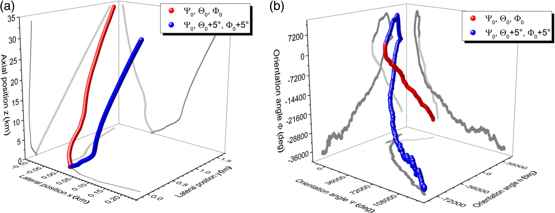 Nevertheless, the outcome of the laser engagement is rather similar, yielding a velocity of for the red dataset and for the blue one, respectively, and the combined efficiency of the operation is raised to slightly more than 6% in both cases. Moreover, tracking allows the reduction of the thrust angle down to 2.7 deg (red dataset) and even 0.4 deg (blue dataset), respectively. However, these data are only two examples among a large variety of possible trajectories, which raises the question how to address this uncertainty of momentum and its direction. 4.3.Target AttitudeFor this purpose, a Monte Carlo simulation was undertaken for a single-laser pulse, cf., Fig. 8. For three sample debris targets, a flat plate, a sphere, and the above-mentioned pliers, the simulation was repeated 500,000 times while orientation and position were randomly chosen for each shot. While the orientation angles were equally distributed, the probability distribution function for the target position exhibited a Gaussian shape with inside the beam spot of . Again, 500 ps was chosen for the simulation of . Fig. 8Results from Monte-Carlo simulations with EXPEDIT comprising 500,000 different initial positions and orientations of the target giving the averaged figures of merit , and the thrust angle for laser-induced momentum generation. Target geometries: plate (10 cm edge length), pliers (12-cm maximum dimension), and sphere (10-cm diameter). Gaussian laser spot profile with 50-cm diameter (full width half maximum, FWHM). 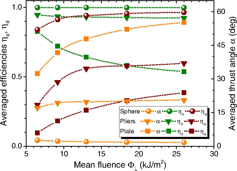 It can be seen from the averaged figures of merit depicted in Fig. 8 that the sphere appears to be the maximally co-operative geometry since small angles indicate that lateral momentum is strongly suppressed, cf., Sec. 4.2.1. The opposite is represented by the plate, which has only surface elements pointing in the same direction, which might yield a large lateral impulse bit. Therefore, in sum, the sphere appears to be much more tolerant with respect to its attitude than the plate, which is indicated by its high value of in comparison with the plate. With respect to both figures of merit, the pliers as an example of real-world irregularly shaped space debris is in between plate and sphere, which seems reasonable. 5.ConclusionsDebris irradiation with a moderate fluence being too close to might yield a considerable loss of efficiency since surface elements with higher do not contribute to momentum generation if . On the other hand, high fluences can lead to high momentum coupling for strong inclinated surface elements yielding unwanted lateral thrust components. Lateral thrust components can principally be avoided with axis-symmetric targets if the symmetry axis coincides with the laser beam propagation axis, which requires perfect alignment of the beam to the symmetry center of the debris target. For some special cases, the target orientation is irrelevant then, e.g., for a cylinder spinning around its symmetry axis or for a sphere, which turns these targets into rather cooperative debris. While symmetric targets require a perfect alignment of beam to the target center for optimum coupling, this might not be the case for asymmetric targets, where an offcenter hit can have the best impact. 6.OutlookUnpredictable lateral impulse components, high sensitivity to pointing precision, and target orientation might be discouraging at first glance. However, preliminary Monte-Carlo studies show the great potential of laser-based removal. Nevertheless, one has to be willing to abandon the idea of deterministic remote laser-based removal at the current state of the art. A probabilistic assessment of the concept is necessary taking into account for the risk to transiently push space debris into an orbit that is even more dangerous than before. But even if the trajectory of dust particles is unpredictable when sweeping the floor, the space is promised to be cleaned in the long run. This would be a great step for spaceflight although a short-laser engagement of a single debris object—now at the cutting edge of current research—is only a tiny little building block of the whole enterprise. AcknowledgmentsThe scientific contributions from Raoul-Amadeus Lorbeer, Carsten Wiedemann, and Markus Roth in fruitful discussions are gratefully acknowledged. A special thanks is expressed to Mikhail Povarnitsyn for providing us with the Polly-2T code, which enabled the setup of the -database used in EXPEDIT. ReferencesH. Klinkrad, Space Debris: Models and Risk Analysis, Praxis Publishing, Chichester, United Kingdom
(2006). Google Scholar
J. N. Opiela,
“A study of the material density distribution of space debris,”
Adv. Space Res., 43 1058
–1064
(2009). http://dx.doi.org/10.1016/j.asr.2008.12.013 ASRSDW 0273-1177 Google Scholar
F. Hoerz et al.,
“Natural and orbital debris particles on LDEF’s trailing and forward-facing surfaces,”
in LDEF: 69 Months in Space. Third Post-Retrieval Symp.,
415
–429
(1995). Google Scholar
P. Krisko, M. Horstman and M. Fudge,
“Socit4 collisional-breakup test data analysis: with shape and materials characterization,”
Adv. Space Res., 41
(7), 1138
–1146
(2008). http://dx.doi.org/10.1016/j.asr.2007.10.023 ASRSDW 0273-1177 Google Scholar
U. Voelker et al.,
“Laser-based space debris monitoring,”
in Beamed Energy Propulsion – Seventh International Symp.,
354
–363
(2011). http://dx.doi.org/10.1063/1.3657011 Google Scholar
W. Schall,
“Orbital debris removal by laser radiation,”
Acta Astronaut., 24 343
–351
(1991). http://dx.doi.org/10.1016/0094-5765(91)90184-7 AASTCF 0094-5765 Google Scholar
C. R. Phipps et al.,
“Orion: clearing near-earth space debris using a 20-kw, 530-nm, earth-based, repetitively pulsed laser,”
Laser Part. Beams-Pulse Power High Energy Densities, 14 1
–44
(1996). http://dx.doi.org/10.1017/S0263034600009733 LPBEDA 0263-0346 Google Scholar
B. Esmiller et al.,
“Space debris removal by ground-based lasers: main conclusions of the European project CLEANSPACE,”
Appl. Opt., 53
(31), I45
–I54
(2014). http://dx.doi.org/10.1364/AO.53.000I45 Google Scholar
A. V. Pakhomov and D. A. Gregory,
“Ablative laser propulsion: an old concept revisited,”
AIAA J., 38
(4), 725
–727
(2000). http://dx.doi.org/10.2514/2.1021 AIAJAH 0001-1452 Google Scholar
D. A. Liedahl et al.,
“Pulsed laser interactions with space debris: target shape effects,”
Adv. Space Res., 52 895
–915
(2013). http://dx.doi.org/10.1016/j.asr.2013.05.019 ASRSDW 0273-1177 Google Scholar
D. A. Liedahl, S. B. Libby, A. Rubenchik,
“Momentum transfer by laser ablation of irregularly shaped space debris,”
in Int. Symp. on High Power Laser Ablation,
772
–779
(2010). http://dx.doi.org/10.1063/1.3507171 Google Scholar
C. Phipps et al.,
“Review: laser-ablation propulsion,”
J. Propul. Power, 26 609
–637
(2010). http://dx.doi.org/10.2514/1.43733 JPPOEL 0748-4658 Google Scholar
D. Baeuerle, Laser Processing and Chemistry, 3rd ed.Springer, Berlin
(2000). Google Scholar
S. I. Anisimov, B. L. Kapeliovich and T. L. Perel’man,
“Electron emission from metal surfaces exposed to ultrashort laser pulses,”
Sov. J. Exp. Theor. Phys., 39 375
–377
(1974). Google Scholar
M. E. Povarnitsyn et al.,
“A wide-range model for simulation of pump-probe experiments with metals,”
Appl. Surf. Sci., 258 9480
–9483
(2012). http://dx.doi.org/10.1016/j.apsusc.2011.07.017 ASUSEE 0169-4332 Google Scholar
M. E. Povarnitsyn et al.,
“Dynamics of thin metal foils irradiated by moderate-contrast high-intensity laser beams,”
Phys. Plasmas, 19 023110
(2012). http://dx.doi.org/10.1063/1.3683687 PHPAEN 1070-664X Google Scholar
S. Scharring, R.-A. Lorbeer and H.-A. Eckel,
“Numerical simulations on laser-ablative micropropulsion with short and ultrashort laser pulses,”
Trans. Jpn. Soc. Aeronaut. Space, Google Scholar
S. Scharring et al.,
“The microlas concept: precise thrust generation in the micronewton range by laser ablation,”
IAA Book Series on Small Satellite, Google Scholar
C. Phipps,
“A laser-optical system to re-enter or lower low earth orbit space debris,”
Acta Astronaut., 93 418
–429
(2014). http://dx.doi.org/10.1016/j.actaastro.2013.07.031 AASTCF 0094-5765 Google Scholar
C. R. Phipps et al.,
“Removing orbital debris with lasers,”
Adv. Space Res., 49 1283
–1300
(2012). http://dx.doi.org/10.1016/j.asr.2012.02.003 ASRSDW 0273-1177 Google Scholar
J. Wilken,
“Modelling of laser-based thrust generation for space debris removal,”
(2015) Google Scholar
K. Tobin,
“Astronaut loses tool bag during spacewalk,”
(2008) http://edition.cnn.com/2008/TECH/space/11/18/endeavour.spacewalk/index.html?eref=time_us October 2014). Google Scholar
E. N. Lorenz,
“Predictability: does the flap of a butterfly’s wings in brazil set off a tornado in texas?,”
The Chaos Avant-Garde. Memories of the Early Days Of Chaos Theory, 91
–94 World Scientific, Singapore
(2000). Google Scholar
BiographyStefan Scharring works as a senior scientist at the Institute of Technical Physics at the German Aerospace Center (DLR). He received his diploma degree in physics from the University of Freiburg in 2000 and his doctoral degree in aerospace engineering from the University of Stuttgart in 2013. His current research interests cover the field of laser-matter interactions and their aerospace applications, in particular, for micropropulsion and space debris removal. Jascha Wilken works as a research engineer at the Institute of Space Systems at the German Aerospace Center (DLR). He received his master’s degree in aerospace engineering from the TU Braunschweig in 2015. Within this degree, he completed research projects at the Institute of Aerodynamics and Flow Technology and at the Institute of Technical Physics of the DLR. For his master’s thesis, he investigated the laser-based thrust generation for space debris removal. Hans-Albert Eckel received his doctoral degree in physics from the University of Kaiserslautern in 1996. He is the head of the studies and concepts department of the DLR, German Aerospace Center Institute of Technical Physics, where he has worked since 1997. His research areas include high-power lasers, atmospheric propagation, laser–matter interaction, and airborne- and space-related laser applications. Since 1998, he has been engaged in the assessment of future applications for laser propulsion. |