|
|
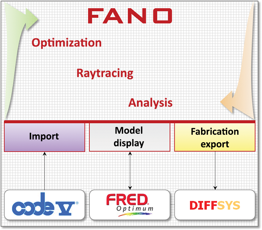
1.IntroductionThe imaging freeform optical systems described here are designed using nonuniform rational basis-spline (NURBS) surfaces. Although NURBS surfaces have been widely used for illumination systems, efforts to optimize them in imaging systems have so far been largely unsuccessful; as a consequence, the optical design community has considered them unsuitable for these systems.1 The major optical design programs CODEV,2 Zemax,3 and FRED4 are not capable of optimizing NURBS grid-type surfaces in imaging systems, a necessary step in freeform optics design. There is no problem with raytracing NURBS grid-type surfaces, which can be accomplished in LightTools,2 FRED,4 and by Zeiss5 with their in-house code; but to succeed in designing NURBS freeform optical systems, an optimization code is required. The motivation for developing the optical design code for fast accurate NURBS optimization (FANO6,7) is based on the mathematical properties of NURBS surfaces, which make them well-suited for representing freeform optical surfaces. The most important property of an NURBS surface is the local control of the surface shape, because it is formed from piecewise splines. Figure 1 shows a third-degree NURBS surface that is formed from cubic basis splines. The surface is defined by the set of grid control points with their weights, together with the knot vectors. Rays 1 and 2 are affected only by the grid control points in their respective shaded sections, because only the 16 closest grid control points affect the surface shape at the ray intersection. To change the direction of ray 1, its 16 grid control points can be moved, leaving the ray 2 unchanged. This local control is important for complex surfaces, which must be represented by thousands of grid control points since each ray is still affected only by its local 16 grid control points. A consequence of this is that the matrices built from the control point variables are better conditioned for solving in the optimization. This local ray control contrasts with a polynomial surface, where all the polynomial terms globally affect every point on the surface. As such, moving ray 1 in the example would require rebalancing all polynomial terms to leave the ray 2 pointing in the same direction. NURBS surfaces also have a number of advantageous properties including the ability to perfectly represent plane and quadric surfaces, with mathematical details covered by Piegl and Tiller.8 Compare this with Gaussian basis functions, with which it is challenging to provide smooth plane and quadric surfaces.9 2.Fast Accurate Nonuniform Rational Basis-Spline Optimization Design CodeThe FANO design code has a fast raytrace engine using optimization algorithms, designed for NURBS surfaces, with the numerical accuracy for large numbers of variables and rays. Parallelizing using OpenGL enabled its speed to be increased by up to a factor of 8 over the first generation, enabling the freeform designs, which use 5000 grid point variables and 50,000 rays. FANO is written in for portability and uses the Intel Math Kernel library for manipulation of the large matrices. Although capable of supporting different degree surfaces, all the results shown in this study are with third-degree NURBS freeform surfaces. Given the large numbers of rays, FANO was designed from the outset for a fast raytrace speed. It can trace 10 million NURBS ray surfaces/s—4000 times faster than the commercial illumination code against which it was compared. FANO avoids the limitations found in current optical design codes for even simple rotational NURBS surfaces,10,11 perhaps because commercial codes are designed to optimize standard optical systems with much smaller numbers of variables and rays, and with algorithms written for speed rather than precision. No success has been reported with any of the current optical design codes in optimizing imaging systems with NURBS freeform surfaces, programmed into their code. FANO’s structure and communication with other programs are shown in Fig. 2. From CODEV, simple starting designs can be imported in the form of point clouds, which are converted to NURBS surfaces. Typically, a regularly spaced NURBS grid is used with the parameterization for the two knot vectors based on the average chord lengths over the surface. There is no export to CODEV since it cannot raytrace NURBS grid surfaces. FRED can raytrace NURBS surfaces, so that the file exchange takes place in two directions. FRED scripts enable the export of the NURBS surfaces and geometry to FANO, which directly reads in the NURBS parameters with no conversion necessary. In a similar manner, FANO can write the same file format to FRED, which is used to confirm all analysis results and to display the resulting designs, such as the figures in this paper. FRED does have a simplex optimization, which is very limited and not suitable for large NURBS optimization problems. The final software package DIFFSYS12 is used for controlling Lincoln Laboratory’s diamond-turning machine, a Moore Nanotech 350FG,13 which can directly diamond-turn freeform surfaces. A subroutine in FANO exports a point cloud in the correct format for import into the DIFFSYS software. DIFFSYS takes the point cloud and fits a surface to the points that the diamond tool will follow. One nice feature of DIFFSYS is that the sagittal position of any point on the interpolated surface can be output, enabling the error to be calculated from the original NURBS surface. Currently, the diamond-turning machines by Moore13 and Precitech14 cannot accept direct NURBS input; however, Schneider optical machines15 freeform diamond-turning machine UPC 400 can accept NURBS surfaces directly. 3.Freeform f 2 Three-Mirror Anastigmat DesignThe following designs show the performance improvement made by using NURBS freeform surfaces in an three-mirror anastigmat design, with the design parameters given in Table 1. For comparison, three designs meeting the optical requirements have been created with the stop at the secondary. The conventional aspheric design is optimized in CODEV and uses tilted and decentered rotational aspheric surfaces with aspheric terms up to the 14th power. The polynomial design is optimized in CODEV and uses the relevant aspheric terms, including the odd powers as well, up to the 10th power. The NURBS freeform design is optimized by FANO with grids of for the mirror M1, for mirror M2, and for mirror M3. No constraints were placed on any of the aspheric terms as well as the NURBS grid points. Table 1Three-mirror anastigmat design parameters.
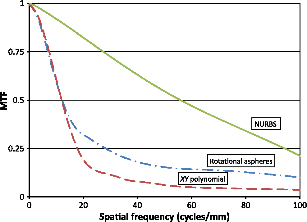
The three designs are shown to the same scale in Fig. 3. The same package volume was available to all design forms, implemented by letting the spaces vary, with just outer bounds on the chief ray distances between the mirrors and ray clearances controlling the mirror angles. Although the spacings between the mirrors in the NURBS design are larger, forcing the conventional and polynomial freeform designs to match those spacings reduced their performance. During optimization the average geometric rms spot size is used as the merit function. Fig. 3Three-mirror anastigmat designs: (a) conventional rotational aspheres design, (b) polynomial freeform design, and (c) NURBS freeform design.  The stop size was left as a variable during optimization yet set to coincide with the secondary mirror. The NURBS freeform design is optimized and analyzed in FANO, while using FRED for confirmation of the analysis and to display the design. Comparing the layouts, the NURBS design has better clearance to the focal plane. In Fig. 4, the rms spot sizes are mapped out over the field of view, showing the improved performance with the NURBS freeform surfaces. The average rms spot size for the conventional aspheric design is ; for the polynomial design ; and for the NURBS design it is , a factor of 2.5 better than the polynomial design. The NURBS design also has less variation in the rms spot size over the field of view. Fig. 4Field map of rms spot sizes for three-mirror anastigmat designs: (a) conventional rotational aspheres design, (b) polynomial freeform design, and (c) NURBS freeform design. 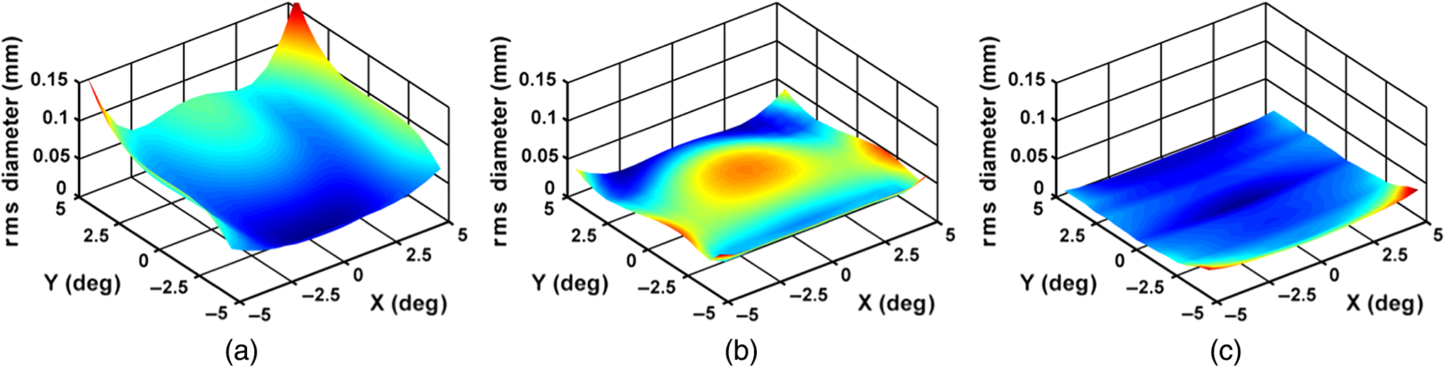 The modulation transfer function (MTF) curves at the center of the field are shown in Fig. 5, calculated at a wavelength of . The curves are the average of the two orthogonal directions at the detector. At , the NURBS freeform system has the highest MTF at 0.55, with the polynomial freeform system having an MTF of 0.05 and the conventional system MTF of 0.15. Although the conventional system and the polynomial freeform systems have similar geometric spot sizes at the center, the higher MTF of the conventional system is due to a high MTF perpendicular to the symmetry plane. The smoothness of the NURBS MTF shows that the spline surface is smooth over this spatial frequency range. 3.1.Mirror Aspheric ShapesGiven the significant performance difference between the NURBS freeform design and the conventional aspheric design, and the polynomial freeform design, then the question is how the aspheric shapes differ. This is analyzed by subtracting the best-fit sphere from each surface and mapping out the aspheric deviation of the surfaces from the best-fit sphere. Figure 6 illustrates the aspheric departure shapes for the mirrors in the three designs. Fig. 6Comparing mirror aspheric departure shapes: (a) conventional rotational aspheres design, (b) polynomial freeform design, and (c) NURBS freeform design. 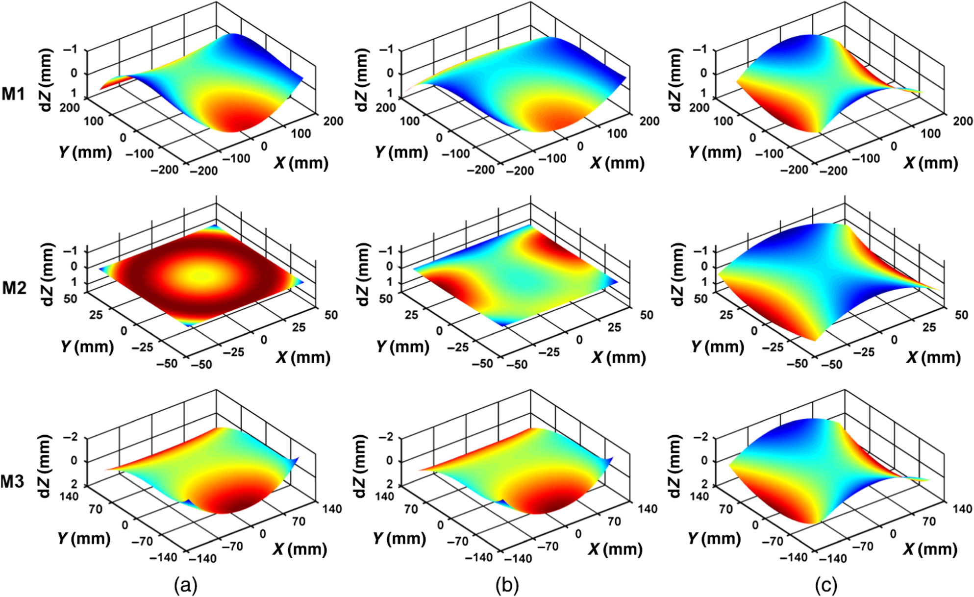 Some interesting differences between the mirror shapes can be seen. For NURBS freeform design, all the mirrors are astigmatic with little coma present. For the secondary mirror M2, the correction for the rotational aspheric design and the polynomial design is much less than that of NURBS design. The power of the aspherics can be assessed from the average rms aspheric deviations from their best-fit spheres, provided in Table 2, together with the average asphericity per surface on the bottom line. Note that the NURBS design has more than twice the asphericity per surface, particularly noticeable for M2 where the aspheric is 33 times more powerful than that for the polynomial design. Table 2Average rms aspheric departures of the mirror surfaces.
3.2.Freeform Telescope DemonstrationTo demonstrate this freeform three-mirror anastigmat design, a half-size version reduced field covering is being constructed with aluminum structure and mirrors, the optomechanical design of which is shown in Fig. 7. The mirrors are held on alignment fixtures to move them in six degrees of freedom during the alignment process, after which they are mounted to the structure with shims for the finished assembly. Diamond-turned fiducials on the mirrors aid in the optomechanical alignment and verification of the clocking of the freeform surfaces after generation. Mechanical structures and diamond-turned references are also accessible on the mirror feet and can be measured without opening the optical assembly. The necessary baffles to eliminate the stray light paths within the optical system have been incorporated, although the extra front baffle is not shown in the figure. One advantage of NURBS surfaces is their accuracy for transferring designs from the FANO optical program to SolidWorks.16 Tests show that measurement sample points on the imported computer-aided design optical surfaces in SolidWorks are within of the corresponding sample points on the optical surfaces in FANO. The NURBS surfaces also enabled model-based 5-axis machining of the mirrors without any orientation errors. Lessons learned so far have led to the emphasis of fiducials on the mirrors for checking the orientation of the freeform surfaces after diamond-turning. For importing the design into SolidWorks, it was found best to import each NURBS surface separately into an optical assembly file so that the local coordinate systems for the grid points were the same among the FANO, FRED, and SolidWorks models. For the diamond-turning only, being able to import point clouds leaves the process open to error since the visualization shows just the surface without the rest of the mirror structure. It is very easy to end up with the freeform surface improperly clocked on the part if not verified. For the hardware, the optical bench is assembled with the initial diamond-turned bare aluminum mirrors, as shown in Fig. 8. The mirrors are checked by the use of computer-generated holograms (CGH), which help to identify any significant errors such as clocking or improper machine programming of the freeform surfaces. Initial tests of the completed assembly show the expected performance, given the figure errors of a few waves on the diamond-turned surfaces. The mirrors have been electroless nickel-plated and figured using magnetorheological finishing (MRF) at QED Corporation,17 based on the measurements using the CGH and subaperture stitching interferometry. These mirrors are currently being aligned in the final assembly, using interferometry and computer-aided alignment techniques. 3.3.Alignment Sensitivity ComparisonAn initial tolerance sensitivity, performed on both NURBS freeform and the conventional rotational aspheric designs for a narrower field of view, established the difficulty of aligning the higher resolution freeform design. The results shown in Table 3 give the change in the average rms spot size over the field for the mirror translations, according to the coordinate axes drawn in Fig. 7. Table 3Alignment tolerance comparison.
Each mirror is moved with a local shift, leaving the global coordinates of the other mirrors in the same place. The detector plane is used as a compensator, with its longitudinal -position, and two tilts optimized to minimize the effect of the aberrations for each movement. For the freeform system, the decentrations of mirrors M2 and M3 introduce the largest changes in the spot size. The root-sum-squared (RSS) of the individual aberrations gives their cumulative change of the rms average spot size. Adding this change to the nominal design performance (found at the bottom of the table) leads to the expected performance, if the mirror translations match the 0.010-mm displacement. The increase in the rms spot size for the freeform design is a 16% increase, compared with an increase of 0.7% for the conventional aspheric design, showing that tight tolerances are required by the higher resolution freeform design. 4.Freeform Correction of an f 3 Ritchey–Chretien TelescopeThis design demonstrates the way that freeform mirrors provide design form solutions, when introduced into optical designs. The requirement for the design was to feed an imaging spectrometer slit at the focal plane of an telescope with a telecentric beam matching the spectrometer pixels, with the requirements given in Table 4. Given the wide wavelength range of visible through infrared, an all-reflective approach was required. Table 4Telescope design parameters.
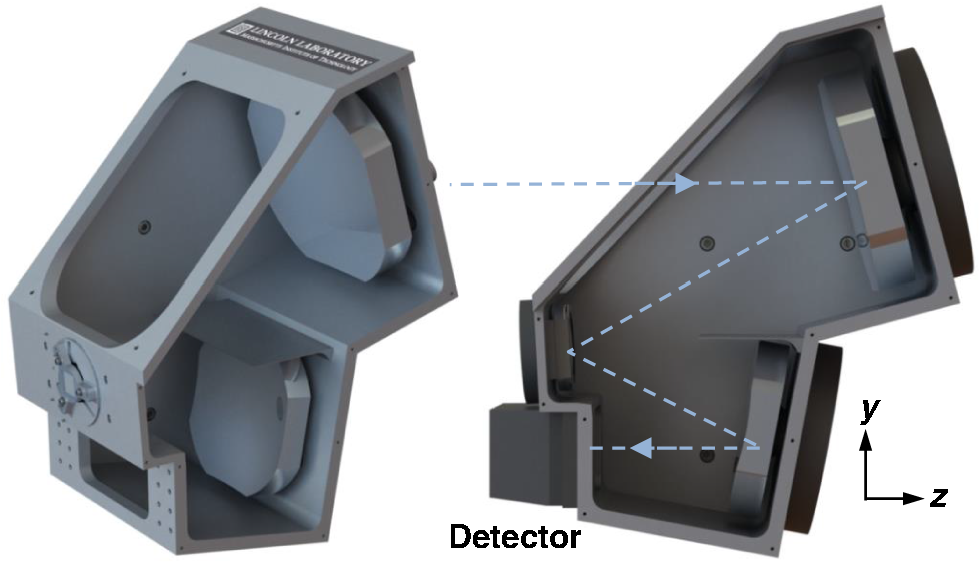
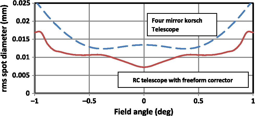
The traditional design solution based on a variant of a three-mirror Korsch type telescope is given in Fig. 9(a). To make the telescope telecentric, a quaternary mirror was introduced after the tertiary, and all four mirrors were optimized together using rotational aspheres to the 16th order. There is very little clearance for the spectrometer entrance slit, which is a difficulty with the design. Fig. 9Telescopes for spectrometer: (a) four-mirror Korsch design and (b) RC telescope with a two-mirror freeform corrector. 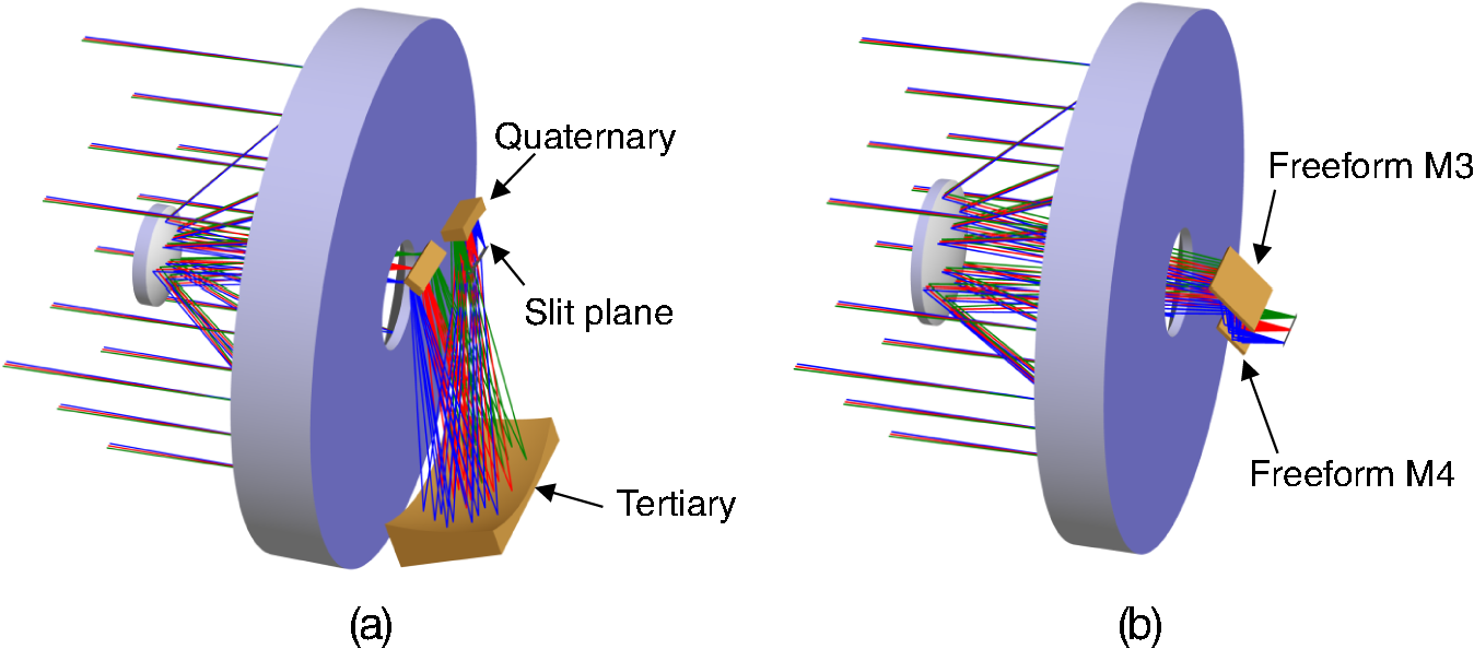 The freeform solution is shown in Fig. 9(b); here, two freeform mirror correctors are used after a Ritchey–Chretien (RC) telescope, flattening and widening the field of view for use with the imaging spectrometer. The large primary and secondary mirrors are fabricated by traditional fabrication techniques. However, the small size of the freeform correctors facilitates their manufacturing utilizing MRF processes. The two mirrors provide a large amount of correction, reducing the uncorrected telescope spot sizes of by a factor of 35 and providing a telecentric exit pupil. This two-mirror freeform corrector is close to the detector and the movement of the small beam footprints over them leverages the power of flexible freeform surfaces, where rapidly changing aberrations across the field can be corrected via complex aspheric surfaces. The mirrors shapes from optimizing the NURBS freeform design shown are shown in Fig. 10, where M3 is based on grid points and M4 on grid points. The mirrors appear to look like cylinders, but the aspheric deviations from best-fit spheres show the complexity of the aspheric shape, with large aspheric peak to valley departures of 0.8 mm for M3 and 1.2 mm for M4. Fig. 10Freeform corrector mirrors: (a) physical shapes and (b) aspheric departures from best-fit sphere. 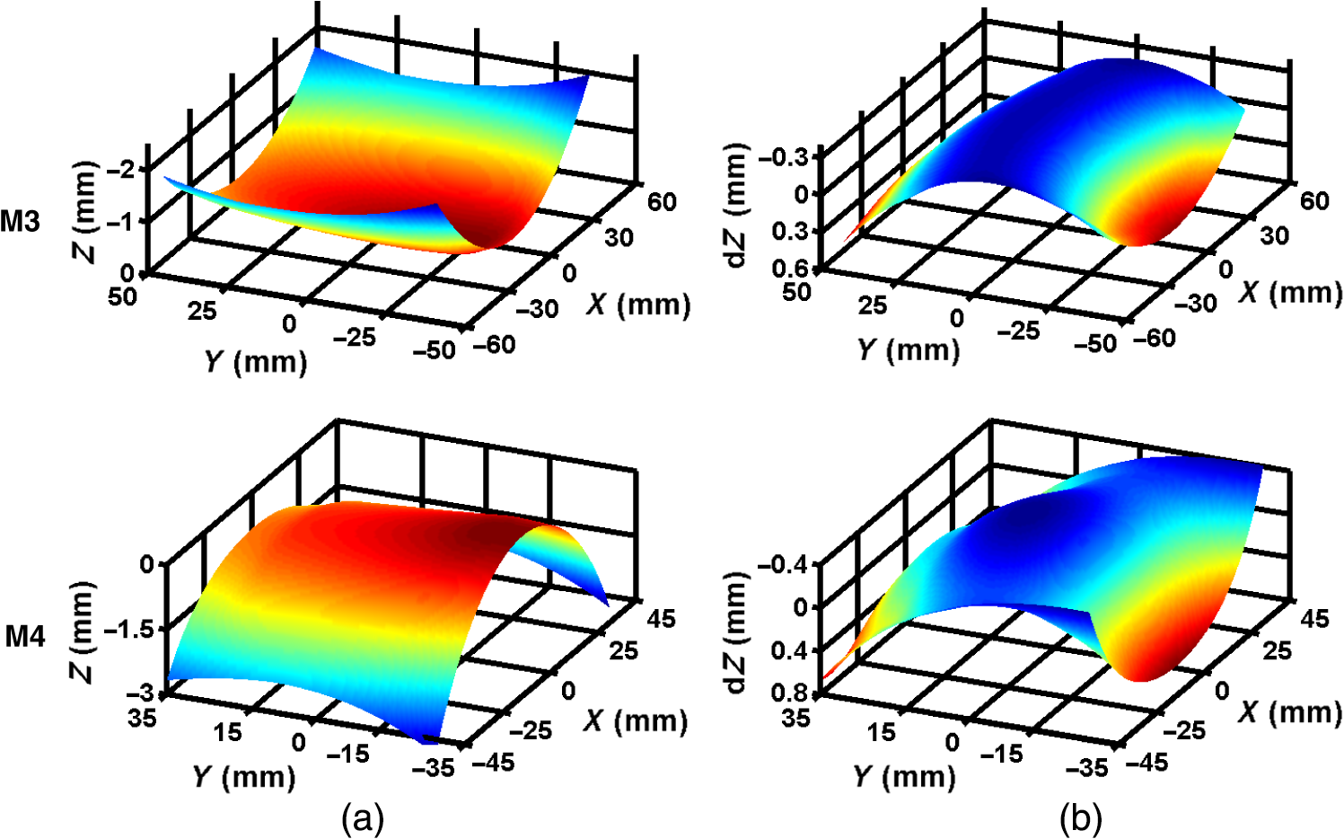 The performance of the two designs is shown in comparison in Fig. 11, where the spot diameters are plotted with field along the spectrometer entrance slit. The Korsch four-mirror variant has an average spot size of whereas the RC telescope with the two-mirror NURBS freeform corrector has an average rms spot diameter of . So the freeform design has reduced the spot sizes by 70% and has also eliminated the large tertiary mirror, saving its weight and structure and freeing up payload volume. 5.ConclusionThe two imaging freeform designs show the performance advantages of using NURBS mirror surfaces. For the three-mirror anastigmat, the spatial resolution improves by a factor of 4 compared with a conventional 16th-order aspheric design and factor of 2.5, compared with a 10th-order polynomial freeform design. The improvement was enabled by using the 4000 grid points in the NURBS freeform design, which resulted in different mirror shapes. The fabrication of a three-mirror anastigmat telescope incorporating these surfaces is described. For the 2-deg slit field imaging spectrometer telescope, the RC telescope with the two-mirror freeform corrector reduced the spot sizes by 70% over the field compared with a four-mirror Korsch telescope, and eliminated the large tertiary. This all-reflective corrector design illustrates how flexible NURBS surfaces can correct rapidly changing aberrations across the focal plane for large telescope systems. As freeform surfaces increase in aspheric complexity, NURBS surfaces provide the way forward in freeform design due to their local surface control and their ease of optimization with thousands of grid control points, demonstrated by these designs. AcknowledgmentsThe authors would like to thank Vicky Gauthier, Christopher Semisch, and Kristin Clark for their support of this work and for the funding provided through the Technology Office. Supporting the demonstration telescope engineering were Dmitry Tolpin for diamond turning, Alan Akerstrom for fabrication, and Lawrence Petrilli and Amanda Smith. This paper is based upon the work supported under Air Force Contract Nos. FA8721-05-C-0002 and/or FA8702-15-D-0001. Any opinions, findings, conclusions, or recommendations expressed in this paper are those of the author(s) and do not necessarily reflect the views of the U.S. Air Force. ReferencesK. Thompson and J. Rolland,
“Freeform optical surfaces,”
Opt. Photonics News, 23
(6), 30
–35
(2012). http://dx.doi.org/10.1364/OPN.23.6.000030 OPPHEL 1047-6938 Google Scholar
P. Jester, C. Menke and K. Urban,
“B-spline representation of optical surfaces and its accuracy in a ray trace algorithm,”
Appl. Opt., 50 822
–828
(2011). http://dx.doi.org/10.1364/AO.50.000822 APOPAI 0003-6935 Google Scholar
M. P. Chrisp,
“New freeform NURBS imaging design code,”
Proc. SPIE, 9293 92930N
(2014). http://dx.doi.org/10.1117/12.2073081 PSISDG 0277-786X Google Scholar
L. Piegl and W. Tiller, The NURBS Book, 2nd ed.Springer-Verlag, Berlin, Heidelberg
(1997). Google Scholar
O. Cakmakcil et al.,
“Meshfree approximation methods for free-form surface representation in optical design with applications to head-worn displays,”
Proc. SPIE, 7061 70610D
(2008). http://dx.doi.org/10.1117/12.798351 PSISDG 0277-786X Google Scholar
H. Chase,
“Optical design with rotationally symmetric NURBS,”
Proc. SPIE, 4832 10
(2002). http://dx.doi.org/10.1117/12.486490 PSISDG 0277-786X Google Scholar
J. Werner et al.,
“An optimization method for radial NURBS surfaces,”
in Deutschen Gesellschaft für Angewandte Optik Proc.,
(2013). Google Scholar
Solidworks 3DCAD is from Solidworks, Waltham, Massachusetts.Google Scholar
BiographyMichael P. Chrisp received his MSc and PhD degrees in optics and physics from London University. He is a senior staff member at Massachusetts Institute of Technology (MIT) Lincoln Laboratory. He is the author of twenty papers, ten patents, and one book chapter. His current research interests include the optical design of space imaging systems, imaging spectrometers, and nonuniform rational basis-spline freeform optics. He is a member of SPIE. Brian Primeau received his PhD in optical sciences from the University of Arizona in 2011. He is now at Ball Aerospace and carried out the work described here while at MIT Lincoln Laboratory. His current research interests include optical metrology, tolerancing, alignment, and system design including freeform optics. He is a member of SPIE. Michael A. Echter is an associate staff member at MIT Lincoln Laboratory and is concurrently pursuing his PhD in mechanical engineering through the University of Rochester, where he also received his MS and BS degrees. His current research interests include the optomechanical design of freeform optical systems, space-based imaging telescopes, and precision deployable telescopes. He is a student member of SPIE. |
|||||||||||||||||||||||||||||||||||||||||||||||||||||||||||||||||||||||||||||||||||||||||||||||||||||||||||||||||||