
|
|
1.IntroductionLaser damage due to laser-focusing on mirror surfaces made of metal easily destroys their optical properties. This is due to the laser-ablative processes generating harsh environmental conditions on the irradiated surfaces. In our case, translating the laser spot, and therefore, the ablation process repeatedly over a surface will eventually lead to surface roughening or even a larger-scaled unevenness over time. Both results are unwanted side effects in the context of laser-ablative propulsion (LAP). Some space missions for the evaluation of general relativity are based on a satellite encapsulating a test mass to shield it from small external forces. The satellite positioning system, e.g., for the Laser Interferometer Space Antenna (LISA) mission, is expected to need a positioning accuracy below 10 nm.1 This requirement restricts the forces which can be tolerated from mechanical components, e.g., installed in the thruster system. To build a thruster without any moving element usually appears to be an impossible task. In the light of LAP,2,3 this task, at least in theory, becomes feasible. The MICROLAS concept4 (micropropulsion by laser ablation) uses electro-optical beam-steering and allows to convert a solid propellant into a series of nNs scaled ablation plumes (Fig. 1). Therefore, the beam-steering does not incorporate any mechanical movement. Furthermore, the propellant itself stays static during thruster operation. Fig. 1MICROLAS scanning scheme. Displayed are the incident laser beam at an incidence angle , the target, the scanning grid with the scan directions and and the ablation plume being emitted from the processed cavity. 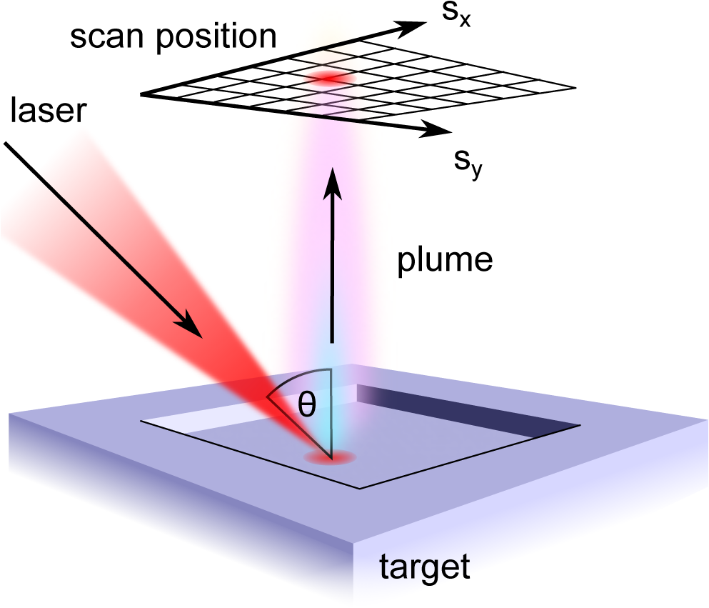 Hence, the MICROLAS concept can be imagined to be one solid arrangement. The access of new propellant is granted by removing the propellant layer by layer. Unwanted changes in surface roughness and unevenness due to the ablation process, therefore, would lead to a laser-induced propellant damage. The commonly unknown aspect in such a process consists of the behavior of the surface over time. Since surface properties and the ablation process are strictly linked to each other5,6 one can conclude from the previous statement, that the temporal evolution of thrust is unknown, too. Slowly changing surface properties, therefore, will lead to noise of the thrust system in the frequency range well below 1 Hz. In our recent work,4,7 we investigated the surface properties of gold and aluminum after ablation with a 10-ps laser source. Now, we changed the pulse duration to 0.5 ns and performed extensive ablation experiments. The newly generated results allow us to compare the surface characteristics after multiple layers of surface ablation in dependency of spot displacement , and laser fluence for the ultrashort-pulse and the short-pulse regime. 2.Theory2.1.Spallation and VaporizationThe significant differences in surface roughness after a single ablation event can be ascribed to the particular ablation mechanisms. Since for ultrashort laser pulses, almost the entire laser energy is temporarily stored in the electron gas before it is coupled into the ion lattice,8 stress confinement of the target provokes that spallation and, for higher fluences, phase explosion are the predominant mechanisms.9 The material is ablated when the rarefaction wave which follows on the initial shock wave exceeds the specific spall strength. Therefore, the heat affected zone of the propellant is rather small and the remaining target material is comparatively cold and exhibits a smooth surface. If the pulse duration is longer than the electron–phonon coupling time of the material, however, laser heating still continues during the laser pulse, which yields a rather large heat affected zone.10 This implies various thermal effects, e.g., vaporization and the formation of a crater rim. Taking into account the pulse durations and of the two laser systems in use and the material-specific electron–phonon coupling times,11 copper and gold have . This marks the so-called picosecond regime for for Cu, Au, and the nanosecond regime for , respectively. In contrast to this, for Al, is in the range of which might suggest some kind of transition. 2.2.Correlation Between Surface Roughness and Thrust NoiseTo further motivate the determination of the surface roughness, one might take a look at theoretical predictions correlating the surface roughness with the absorbed energy.12 As soon as multiple scattering takes place, the laser absorption is raised significantly, which in turn decreases the ablation threshold .5,6 The (cold) absorption on highly reflecting materials as, e.g., aluminum can be approximated linearly by the effective number of reflections.12 For a given surface correlation length and a Gaussian height distribution, this results in a linear correlation to surface roughness , easily doubling the absorbed laser intensity.12 With the above knowledge and a few assumptions, a linear approximation can be deduced to indicate the amount of thrust noise introduced. ( depicts the standard deviation of , its mean or expected value.) First, we may assume that the average surface roughness and the surface correlation length are of the same size. represents the characteristic width of the autocorrelation function of the surface profile.12 Keeping constant for all, introduces a linear shift of the absorbed fluence depending on the surface roughness . This again translates the fluence-dependent coupling coefficient . The coupling coefficient depicts the ratio of generated thrust to the average laser power used. Second, using the Sinko model,13 a realistic intermediate slope of half way to its maximizing fluence () can be deduced dividing by . Finally, adding the relation from Bergström et al.12 for aluminum, , leads to the following approximation: The approximation states that under relevant process parameters one may obtain a relative thrust noise proportional to the relative deviation in surface roughness. The surface roughness variations may be due to roughness variations in time as well as surface positions. In the latter case, an additional source of error has to be considered. The surface might have a large scale roughness or rather unevenness. Since the thrust vector typically points perpendicular to the local surface, this leads to a misaligned thrust vector, which primarily will generate thrust noise perpendicular to the desired thrust direction. Similar to the previous calculation, a simple geometric consideration leads to depending on the uncertainty in the slope of the surface in rad. To connect these approximations with, e.g., the LISA requirements of a power spectral density [] of , one has to know the frequency space over which the noise will be distributed. For the sake of the argumentation, we will assume now that white noise (WN) is generated with a constant starting from 0 Hz up to . In this case, the flowing relation has to be considered14 with , may not exceed , at which a thrust allows for a maximum relative error of 5%. Bearing these considerations in mind, we will focus on the surface roughness as a primary indicator for problematic constellations.3.Materials and Methods3.1.ExperimentsThe scanning of multiple layers of material was performed using hatching patterns. A hatching pattern describes the procedure of turning the scan direction , in our case by 10 deg, after every layer has been scanned. With this method, 18 layers were removed and the generated surface was analyzed using a white light interferometer (Veeco NT9100). While the hatching angle was fixed to 10 deg, the laser fluence, and therefore, the crater radius was varied. Furthermore, the line and spot displacement were kept equal and varied to create different amounts of ablation crater overlap (Fig. 2). Fig. 2Ablation pattern scheme.4 Parameters for a hatching scan are spot displacement , line displacement , hatching angle , and spot radius .  The laser incidence angle (Fig. 1) was set to 0 deg. This allowed to use a conventional scanning setup and access the entire target surface. Laser absorption and coupling coefficient show only a minor dependency up to an incidence angle of 60 deg.12 As a laser source, a solid-state 10-ps pulse duration system (Duetto, Time Bandwidth/Lumentum) was used, while a rather small microchip laser (PNP-B08010, Teem Photonics) was able to deliver a pulse duration of 0.5 ns. To omit laser power variations, a Faraday isolator was introduced after the microchip laserhead. Both laser systems emit at a wavelength of 1064 nm and are capable of delivering tens of microjoules pulse energy. Laser power was detected by a separated light beam and a pulse energy measuring head (PE9-F, Ophir). To calibrate the effective pulse energy available at the target, simultaneous power measurements with a second laser power head (12A-P, Ophir) placed in the target chamber were performed twice a day. With the microchip laser, a telescope was used to adjust the beam diameter. The laser spot diameter for the 10-ps system was 47 and for the 0.5-ns system. Before entering the scan head, a quarter-wave plate was introduced and adjusted to generate circularly polarized light. Circular polarization will prevent the results from being biased by asymmetries due to beam polarization. The beam then was redirected into the scan head (intelliSCAN 14, Scanlab) and focused by a telecentric -theta objective () through an antireflective (AR)-coated vacuum window. In the case of the 0.5-ns pulse duration, an AR-coated window was added within the vacuum chamber to prevent coating of the chamber window by the ablation plume. The focus was placed on the targets’ surface and scan experiments were performed at a vacuum below . As target materials, aluminum, copper, and gold were chosen. The surface was polished to optical mirror quality by KUGLER. 3.2.SimulationsHatching patterns were simulated by linear superposition of idealized single ablation crater profiles.4 The concept includes the introduction of an idealized ablation crater using the radially dependent fluence of a Gaussian laser spot to calculate a radially dependent depth The function can be fitted to the experimental or simulation data via parameters a and , where denotes the peak fluence of a Gaussian-shaped laser spot and the material threshold fluence. This function always leads to a parabolic profile and is defined for a laser fluence above the threshold (). The crater radius then defines the distance of the center to the rim of the crater with being the laser spot radius at relative peak intensity. This leads to the crater profiles depicted in Fig. 3. Placing these depth profiles in two-dimensional (2-D) hatching patterns (Fig. 2) and adding their depths linearly lead to an approximated simulation of pattern induced surface roughness. These virtual hatching patterns can be adapted to the physical parameters of the measurements and thereby allow to deduce and compare the expected surface roughness .Fig. 3Estimated ablation crater from simulation data. Fluence profiles with corresponding crater profiles (2-D simulation results) for laser ablation of gold with 6 and , resp. The crater diameters depend on the ablation threshold fluence and therefore vary with the laser pulse fluence, whereas the radius of the laser spot is kept constant. Laser parameters: , , circular polarization. 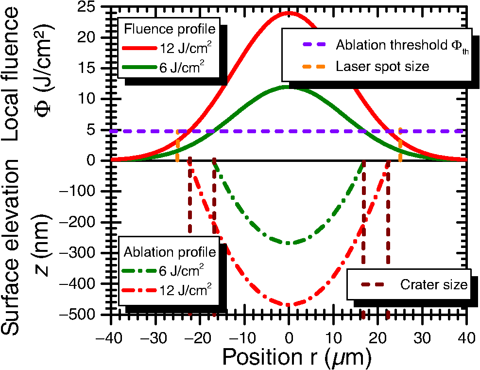 3.3.EvaluationFigure 1 shows the surface of a processed cavity. To determine the surface roughness, a region of interest was chosen and the average deviation from the mean value of all chosen pixel values was interpreted as the surface roughness . 4.Results and Discussion4.1.Fourier InterpretationIf the ablation depth can be added linearly to predict the performance of a chosen hatching pattern, a Fourier interpretation and prediction for the results can be performed. Figure 4 shows the Fourier transformation of the ablation depth of a single crater (similar to Fig. 3). It can be seen that the amplitude of the signal decays for higher spacial frequencies and . The Fourier representation of a perfectly flat surface would be given by one single signal at the zero frequency (). A simple hatching pattern as, e.g., a regular grid, can be interpreted as a folding of the crater with the grid. In Fourier space, this is equivalent to the multiplication of the Fourier spectrum of the crater profile (contour plot in Fig. 4) with the Fourier transformation of the hatching grid. Since the Fourier transformation of a regular grid with grid constant, results in a regular grid, with inversely proportional grid constants , a grid with a higher density or larger crater overlap (smaller ) will push the grid points away from the zero frequency (colored rectangles in Fig. 4). Due to the decay at higher frequencies and the multiplication in Fourier space, less and less amplitude next to the zero frequency will be accumulated and, due to the concentric rings of the FT crater profile, will produce modulations contributing to the surface roughness as shown in Fig. 5. Fig. 4Fourier transformation of the depth response for a crater simulated with a fluence of and a pulse duration of on aluminum. Top and right diagrams display cross sections through the central (zero) frequency in and direction. The rectangular markers in the color plot indicate the positions of the lowest grid frequencies of the Fourier transformed hatching grid pattern. The relative overlap of the corresponding hatching pattern is indicated in per cent on the right top diagonal. For visibility reasons, the rotated grids of the hatching pattern were omitted. 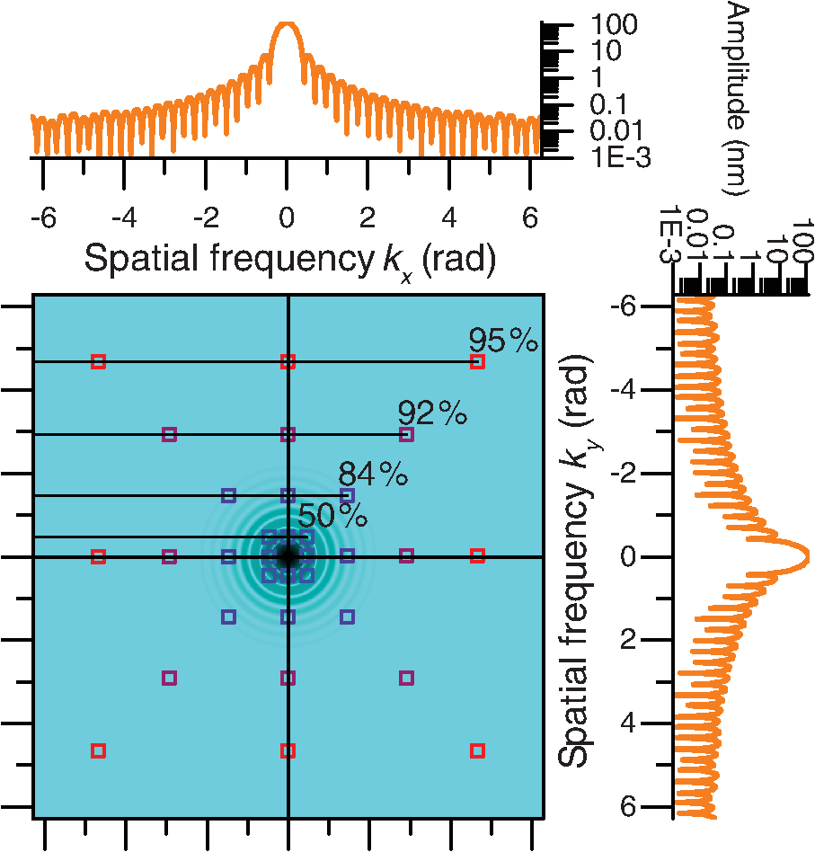 Fig. 5Relative surface roughness created by folding the ablation crater with the hatching grid using FFT filtering. Furthermore, the maximum relative amplitude at the Fourier grid multiplication points (omitting the zero frequency ) plotted over the crater overlap. Simulated pulse duration is 10 ps, laser wavlength 1064 nm, fluence of , and a spot radius of on aluminum.  Compared to earlier findings,4 a Fourier domain filter approach shows a similar behavior ( in Fig. 5). Furthermore, a strong correlation to the maximum amplitude in Fourier space (next to the zero frequency) after the grid folding process suggests that the inverse grid points closest to the zero frequency dominate the surface roughness (“normalized maximum” in Fig. 5). The Fourier transform of the crater profile (Fig. 4) shows radii with zero contribution. If the Fourier transformed grid points closest to the zero frequency roughly coincide with these areas, their missing contribution to the surface roughness creates a local minimum. This result is reproduced in the roughness plot of Fig. 5. 4.2.Roughness MeasurementsThe surface roughness clearly shows modulations plotted against spot displacement (Fig. 6) as well as the laser fluence (Fig. 6 left aluminum). Since there is a modulation visible, optimal parameters for the scanning process can be defined. This behavior can be deduced from the simulations of the hatching patterns (Fig. 5). The simulation results also suggest that these optima correlate linearly with the effective crater diameter calculated by Eq. (6). Therefore, it should be possible to plot curves through the roughness plots, which dominantly follow a path of minimum roughness (compare dashed lines in Fig. 6). From Fig. 5, it can be deduced that the first resonance can be expected at 42% crater overlap ( crater diameter). Using the corresponding ablation threshold and spot diameter in Eq. (6) as determined by single ablation crater Liu plots,15 we introduced separate graphs (dashed lines) in Fig. 6. Fig. 6Surface roughness of copper, gold, and aluminum treated with a hatching pattern and a laser pulse duration of 500 ps (left) and 10 ps (right). Dashed lines indicate expected optimum roughness, while the positions marked by an “x” indicate the parameter sets, which were experimentally investigated. 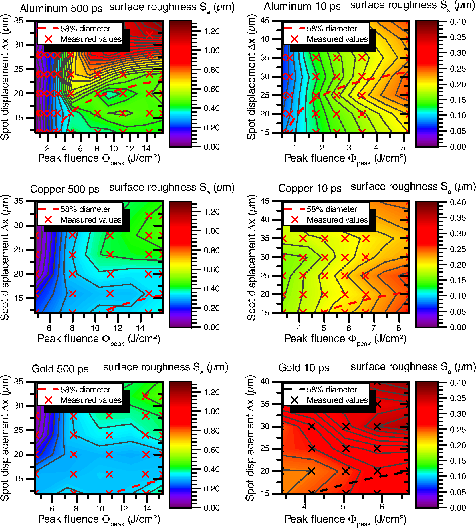 Spot displacements in both regimes are chosen slightly differently, since the spot diameter for both laser systems differed ( and ). Therefore, the curves of the 500-ps experiments are drawn for smaller displacements. Surprisingly, the expected behavior can be seen at least partially for aluminum in both pulse regimes as well as for copper at the 500-ps pulse duration. The other measurements differ distinctly from the expected behavior. The encountered differences can be explained by the incubation effect.5 This effect has a tendency to reduce the ablation threshold which, taking into account Eq. (6), should lead to an underestimation of the optimum spot displacement. This leads to curves that in the displayed plots (Fig. 6) always lie at lower spot displacements than the actually observed optimum. Despite the surface roughness, other aspects of the laser-ablative process have to be taken into account, too. Optimum specific impulse and laser impulse coupling coefficient do not necessarily coincide with the optimum of the surface roughness. These values depend on the applied laser fluence . For 500-ps pulses, we were able to observe a surface roughness which was almost independent from . These optimum spot displacement values, concerning the surface roughness, might allow to benefit from a freely chosen laser fluence. A surprising aspect in comparing the ultrashort-pulse ablation regime (here 10 ps) and the short-pulse (here 500 ps) ablation regime is the demonstration of similar roughness generated at the optimal spot displacement regions. Single ablation craters in the short-pulse regime, generated by vaporization and melting, typically lead to a chaotic raising of the crater rim. These effects lead to bigger surface modulations compared to the ultrashort-pulse regime dominated by spallation and phase explosion.4 The effect of applying multiple layers of densely placed ablation spots appears to compensate for this difference effectively. The last aspect visible in all roughness plots is a low surface roughness for low laser fluence. This behavior can be explained by the minor amount of material ablated at the threshold fluence and below. With no ablation taking place, the surface is not expected to become rough. Therefore, these values are excluded from the discussion. 5.Conclusion and OutlookThe ablation of the propellant surface poses an essential element in the MICROLAS concept. By this, not only thrust is generated, but new propellant also becomes accessible in a layer by layer manner. We were able to show that with 10-ps laser pulse duration as well as 500-ps laser pulse duration the surface roughness can be optimized by choosing an optimal spot density. Furthermore, we could show that, for well-chosen spot densities, the roughness changes by less than a factor of two when switching between the regimes. This result allows the system optimization to be focused on other relevant parameters as, e.g., the specific impulse. Here, simulations show a great benefit in choosing a short-pulse laser system.16,17 Since the measurements only include the ablation of 18 successive layers, future work will investigate the roughness change with longer laser irradiation times. The linear model would predict a steady rise of the surface roughness. Since physical effects as, e.g., melting of the local surface are involved in the ablation process, some kind of time-independent saturation may take place. If so, this again would be beneficial for the development of a MICROLAS thruster. AcknowledgmentsWe want to thank all staff at the DLR and IFSW which by their daily work made it possible to perform the work presented above. ReferencesR. Leach and K. Neal,
“Discussion of micro-newton thruster requirements for a drag-free control system,”
(2002). Google Scholar
G. Askar’yan et al.,
“Light-reaction acceleration of macro-particles of matter,”
ZhETF Pisma, 5 258
–260
(1967). Google Scholar
A. Kantrowitz,
“Propulsion to orbit by ground based lasers,”
Aeronaut. Astronaut., 10 74
–76
(1972). Google Scholar
S. Scharring et al.,
“The MICROLAS concept: precise thrust generation in the micronewton range by laser ablation,”
IAA Book Series on Small Satellite,
(2016). Google Scholar
P. Mannion et al.,
“The effect of damage accumulation behaviour on ablation thresholds and damage morphology in ultrafast laser micro-machining of common metals in air,”
Appl. Surf. Sci., 233
(1), 275
–287
(2004). http://dx.doi.org/10.1016/j.apsusc.2004.03.229 ASUSEE 0169-4332 Google Scholar
D. K. Sardar, M. F. Becker and R. M. Walser,
“Multipulse laser damage of GaAs surfaces,”
J. Appl. Phys., 62
(9), 3688
–3693
(1987). http://dx.doi.org/10.1063/1.339250 JAPIAU 0021-8979 Google Scholar
L. Pastuschka,
“Optimization of material removal for laser-ablative microthrusters,”
IFSW, University of Stuttgart,
(2015). Google Scholar
S. Anisimov, B. Kapeliovich and T. Perelman,
“Electron emission from metal surfaces exposed to ultrashort laser pulses,”
Zh. Eksp. Teor. Fiz, 66
(2), 375
–377
(1974). Google Scholar
L. V. Zhigilei, Z. Lin and D. S. Ivanov,
“Atomistic modeling of short pulse laser ablation of metals: connections between melting, spallation, and phase explosion,”
J. Phys. Chem. C, 113
(27), 11892
–11906
(2009). http://dx.doi.org/10.1021/jp902294m Google Scholar
B. N. Chichkov et al.,
“Femtosecond, picosecond and nanosecond laser ablation of solids,”
Appl. Phys. A, 63
(2), 109
–115
(1996). http://dx.doi.org/10.1007/BF01567637 Google Scholar
B. Hüttner and G. C. Rohr,
“On the theory of ps and sub-ps laser pulse interaction with metals: Ii. spatial temperature distribution,”
Appl. Surf. Sci., 126
(1), 129
–135
(1998). http://dx.doi.org/10.1016/S0169-4332(97)00592-8 ASUSEE 0169-4332 Google Scholar
D. Bergström, J. Powell and A. Kaplan,
“The absorption of light by rough metal surfaces—a three-dimensional ray-tracing analysis,”
J. Appl. Phys., 103
(10), 103515
(2008). http://dx.doi.org/10.1063/1.2930808 JAPIAU 0021-8979 Google Scholar
C. Phipps et al.,
“Review: laser-ablation propulsion,”
J. Propul. Power, 26
(4), 609
–637
(2010). http://dx.doi.org/10.2514/1.43733 JPPOEL 0748-4658 Google Scholar
M. D. Kochanczyk et al.,
“Power spectral density integration analysis and its application to large bandwidth, high precision position measurements,”
Proc. SPIE, 8458 84580H
(2012). http://dx.doi.org/10.1117/12.929349 PSISDG 0277-786X Google Scholar
J. Liu,
“Simple technique for measurements of pulsed Gaussian-beam spot sizes,”
Opt. Lett., 7
(5), 196
–198
(1982). http://dx.doi.org/10.1364/OL.7.000196 OPLEDP 0146-9592 Google Scholar
S. Scharring et al.,
“Low-noise thrust generation by laser-ablative micropropulsion,”
(2015). Google Scholar
S. Scharring, R.-A. Lorbeer and H.-A. Eckel,
“Numerical simulations on laser-ablative micropropulsion with short and ultrashort laser pulses,”
Trans. Jpn. Soc. Aeronaut. Space Sci., TJASAM 0549-3811 Google Scholar
BiographyRaoul-Amadeus Lorbeer received his diploma degree in physics from the University of Hanover in 2007 and his doctor’s degree from the same university in 2012. He is a research scientist at the Institute of Technical Physics at the German Aerospace Center (DLR). His current research interests are focused on laser-ablative thrust generation for aerospace applications, in particular for micropropulsion and space debris removal. Stefan Scharring received his diploma degree in physics from the University of Freiburg in 2000 and his doctor’s degree in aerospace engineering from the University of Stuttgart in 2013. He works as a senior scientist at the Institute of Technical Physics at the German Aerospace Center (DLR). His current research interests cover the field of laser–matter interactions and their aerospace applications, in particular for micropropulsion and space debris removal. Jan Pastow received his BEng degree engineering and design from DHBW Stuttgart in 2012 and his MSc degree in technology management from the University of Stuttgart in 2016. He works as a scientific assistant at the Institute of Technical Physics at the German Aerospace Center (DLR). Currently, he is continuing his research on laser-ablation propulsion from his master's thesis. Daniel Johannes Förster graduated in physics and mathematics at the University of Stuttgart in 2013. He is a research scientist at the Institut für Strahlwerkzeuge (Stuttgart Laser Technologies) at the University of Stuttgart. His current research interests cover fundamentals of laser-matter interaction and laser micromachining. Hans-Albert Eckel received his doctor’s degree in physics from the University of Kaiserslautern in 1996. He is head of the Studies and Concepts Department of the German Aerospace Center (DLR), Institute of Technical Physics, where he has worked since 1997. His research areas include high-power lasers, atmospheric propagation, laser matter interaction, and airborne- and space-related laser applications. Since 1998, he has been engaged in the assessment of future applications for laser propulsion. |


