|
|
1.IntroductionThe array of scientific and technological applications utilizing high-power/intensity laser pulses to deposit energy and modify solid-state materials is continuously expanding. The laser energy is coupled into the material to generate localized high temperatures and pressures while the material becomes thermodynamically unstable. The ensuing material response is associated with an explosive process that leads to material removal and mechanical damage of the surrounding volume. Measurements of dynamic parameters of these explosive processes (such as the generation and propagation of the shock wave and the ionized gas, and kinetics and distribution of ejected and redeposited particles as a function of laser parameters and energy deposited) have provided insight into the dynamics of the generated ejection plume.1–8 Experimental evidence and modeling suggest that the material is exposed to pressures of the order of 10 GPa and temperatures of the order of 1 eV.9–12 Considerably less information exists on the relaxation of the metastable superheated material and the surrounding “cold” material that was exposed to high pressures and stresses generated during the process. The relaxation process may include vaporization, particle ejection, radiative cooling, and phase transformation. This is a complex problem that is very challenging to describe in detail using current modeling tools. In the field of laser damage in optical materials for inertial confinement fusion (ICF)-class laser systems, the coupling of the laser energy to the optical material is unintentional and facilitated by the presence of some sort of absorbing defect. However, the ensuing physics is analogous to the general case of laser-induced ablation/breakdown. The process initially creates a volume of superheated material at near-solid density that exhibits extreme gradients of temperature and thermophysical property values, whereas relevant phase diagrams are not known. It is characteristic that by creating damage on the exit surface of an optic, the plasma front expands toward the bulk (upstream from the laser beam), thereby creating the proper conditions to generate a larger volume of superheated material that can aid in the execution of experiments to study its transient properties. The physics involved in this process, at the boundaries of warm-dense-mater-regime, is not well understood, although it is of fundamental importance for all related fields of use. We have recently presented work related to the relaxation of laser superheated (via nanosecond pulses) fused silica suggestive that the relaxation process involves a number of distinct phases that include the delayed explosive ejection of microscale particles for a duration of the order of after the pressure of the superheated material is reduced to .13 The present work focuses on providing a more-detailed characterization of the ejected particles as a means to probe the transient structure of the superheated material in fused silica. Specifically, we hypothesize that the morphology of the ejected particles generated during exit-surface damage in fused silica is governed by the state of the superheated material at the time of ejection of each particle. This in turn can help develop a better understanding of the relaxation process and dominant mechanisms and origin of the structural features of the resulting material modifications. In addition, this work helps to better understand the impact on adjacent optical elements that may be in the path of the ejected particles during damage initiation or growth. Specifically, we demonstrate that the temperature and kinetic energy of a subset of the ejected particles are sufficiently high to initiate irreversible modification on intercepting silica substrates. The observed modifications include mechanical damage of the substrate as well as tight attachment (fusion) on the substrate of segments of melted particles. 2.Experimental ArrangementA schematic diagram of the experimental setup is shown in Fig. 1. In brief, damage on the exit surface of a “donor” fused-silica plate was induced using 1064-nm, 10-ns full width half maximum (FWHM) intensity laser pulses having an estimated peak fluence on the exit surface of the order of . The beam was focused using a 10-cm-focal-length lens about 5 mm behind the exit surface of the donor sample to ensure damage initiation on the exit surface but not on the front surface or inside the bulk. The donor sample was positioned at an angle of about 45 deg with respect to the direction of laser beam propagation so that the resulting jet of particles (always formed in a direction orthogonal to the exit-surface plane, see Sec. 3) is offset from the laser beam propagation direction. This jet was subsequently intercepted by a second fused-silica substrate (the “collector” sample) having its surface nearly parallel to the surface of the donor sample. The two samples were separated by a distance of and shifted to avoid exposure of the collector sample to the pump laser beam. As a result, the molten particles (within the particle jet) are collected on the upper quadrant of the collector sample. All experiments were performed in ambient air. Fig. 1Experimental setup depicting the damaged particle collection geometry optimized to facilitate the collection of molten particles within the formed jet of high-speed ejected particles in ambient conditions. 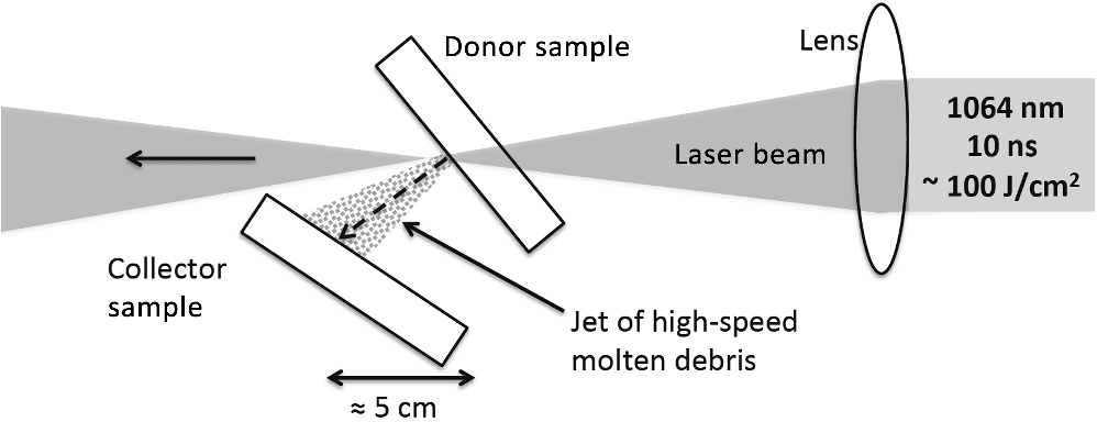 A “cloud” of particles was observed by naked eye (with proper illumination) after each laser exposure extending about 15 cm away from the donor sample. This cloud of particles was observed to follow the airflow in the laboratory environment. Therefore, particles from the debris cloud would also settle on other, more-distant locations of the collector sample; however, those collected debris particles primarily had the appearance of mechanically fragmented silica rather than melted material following exposure to high temperatures/pressures. The configuration shown in Fig. 1 was chosen after attempting various particle collection geometries because it favored the collection of particles that had been exposed to high temperatures and therefore undergone melting. Such particles exhibiting a plurality of morphologies [as revealed by scanning electron microscopy (SEM)] were predominantly observed within a -diameter region, where the particle jet was intercepted by the collector sample. On the other hand, fragmentation particles were observed over the entire surface of the collector sample. 3.Experimental ResultsWe first tested the underlying hypothesis concerning the particle collection geometry discussed above. Namely, the particle jet is formed orthogonally to the exit surface of the sample when irradiated by a laser beam at 45 deg with respect to its surface. Using a time-resolved microscope system described in detail elsewhere,14 we captured images of the jet produced using the pump geometry mentioned above and a typical example is shown in Fig. 2. In brief, using the same pump laser, the microscope system was positioned orthogonal to the laser beam propagation direction to enable side-view imaging of the sample’s surface while the sample was rotated 45 deg with respect to the laser beam propagation direction. The strobe light back-illumination was provided by 532-nm, 4.5-ns (FWHM) pulses from a frequency-doubled Nd:YAG probe laser. The temporal delay of the probe pulses with respect to the pump pulse was adjustable, thereby making it possible to capture images of the ejected particles in-flight at predetermined delays after exposure to the pump pulse. The exemplary image shown in Fig. 2 was captured with the probe pulse-delay at 700 ns showing the formed jet of ejected particles. As the camera shutter was open for and the bandpass filter for 532 nm was eliminated, the recorded image contained both the time-integrated plasma emission and time-resolved particle jet. In addition, a schematic depiction of the donor and collector samples, as well as the geometry of laser irradiation, is also superimposed in Fig. 2 to facilitate a better understanding of the excitation geometry. These results verified that a jet of ejected particles traverses vertical to the surface of the sample from the point of exit-surface laser-induced damage. Fig. 2Time-resolved image captured at 700-ns delay showing the formation of a jet of ejected particles traversing normal to the sample’s surface from the point of exit-surface laser-induced damage. A schematic depiction of the donor and collector samples (not to scale), as well as the geometry of laser irradiation, is superimposed for clarity. 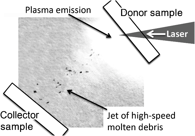 Recent work13 by our research team proposed that, following the superheating of a material volume via a laser pulse under excitation conditions similar to those presented in this study, the material relaxation process includes four discrete phases giving rise to ejected material with distinctive morphologies. These phases, along with their estimated pressure range/duration, include:
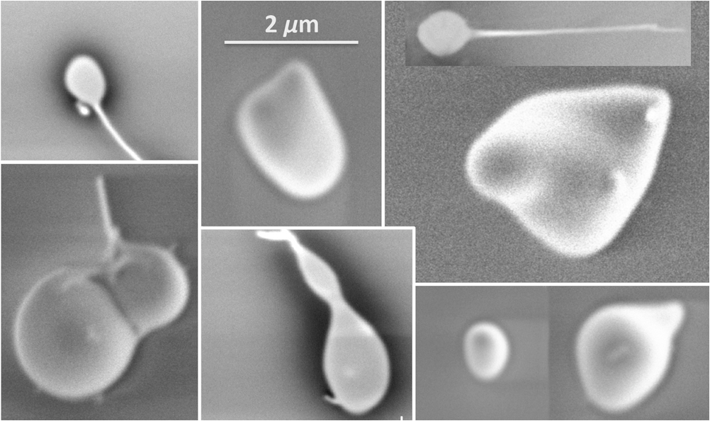
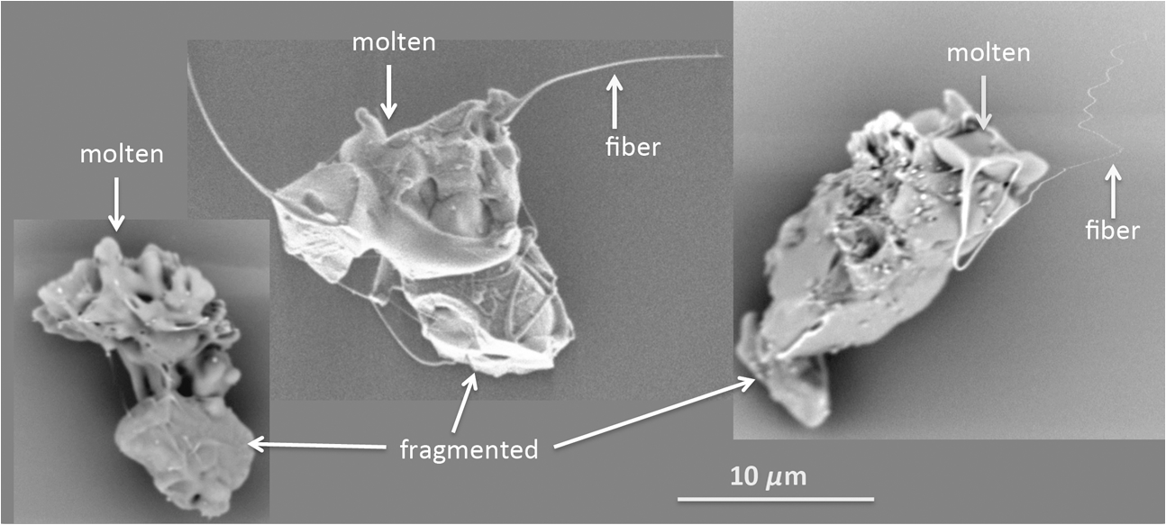
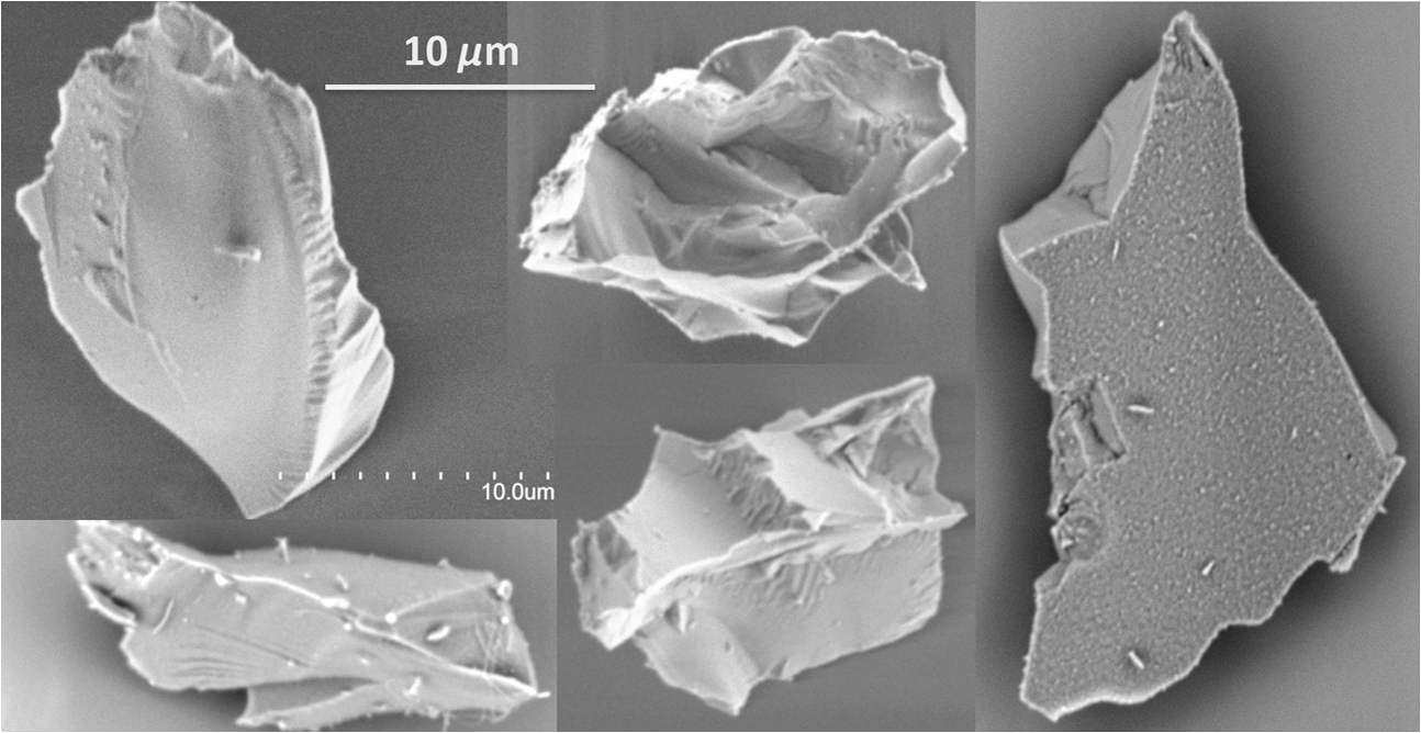
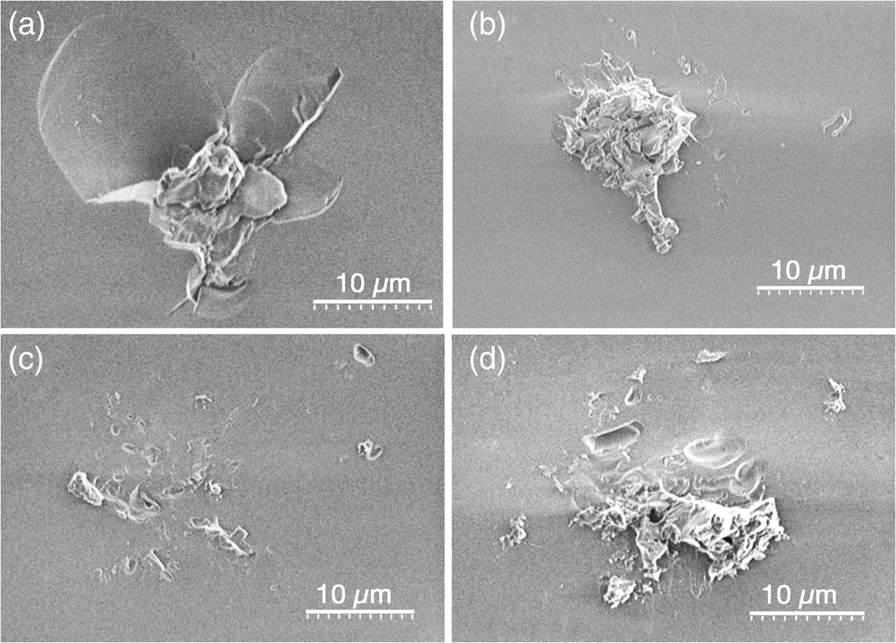
Microscopic particles are ejected only during phases 2 to 4, while the speed of the particles declines as the pressure and temperature of the superheated material decrease. Figure 3 shows the speed of the ejected particles and corresponding pressure of the superheated material as a function of the time of ejection (delay from the pump pulse) as presented in Ref. 13. The relationship between pressure and speed of the particles arises, to first-order approximation, from the fact that the internal energy of the particles remains unchanged during separation from the superheated material. Therefore, the kinetic energy of a particle is about equal to the work of the ejected material just before separation. Consequently, the pressure of the superheated material at the time of particle ejection is directly obtained from kinetic energy density of each particle. During the relaxation, the temperature of the superheated material decreases until a thermodynamically stable liquid phase is reached (at ). Previous work15 suggested that the temperature of ejected particles can be as high as . Therefore, we consider that the temperature of the superheated material during the material ejection process is in the range of to 3000 K. Consequently, the viscosity of the material continuously changes with delay time during the ejection process. This in turn should affect the spatial characteristics of the melted particles. The work of Doremus16 provides a good approximation of the viscosity of silica at the relevant temperature range. Accordingly, the particles were categorized in four types based on their physical characteristics. Fig. 3The speed of the ejected particles and corresponding pressure of the superheated material as a function of the delay time (from the pump pulse) of the particles’ ejection from the laser superheated material pool formed inside the surface of fused silica. The three phases of the material ejection process involving microscopic particles in correlation to the four types of particles ejected are also shown. 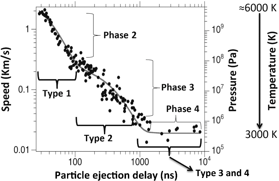 Type 1 particles correspond to the particles ejected during phase 2. These particles are small in size (as demonstrated in previous time-resolved imaging studies)17,18 and have speeds between about and . Representative examples of type 1 particles are shown in Fig. 4. They have the appearance of small liquid droplets having a diameter of the order of or less. Two or more attached droplets are often observed generating more-complex shapes. These particles were ejected during the explosive release of the confined superheated material (phase 2) and because of their low viscosity (expected to be similar to motor oil to maple syrup), the surface tension governs the shape of the particles, leading to nearly spherical particles. A fiber “tail” (or remnants of that) with diameter of the order of 100 nm is often observed. The fiber tail was conceivably formed during the separation from the liquid pool. The particles often have a partial appearance of splats, indicative that they have reached the collector sample while still in the liquid phase. As previously discussed,15 these hot ejected particles rapidly form a shell of colder material in the outer surface, aided by evaporative cooling, but their interior remains hot. This shell halts the evaporative cooling process, and the interior slowly cools thereafter via heat conduction, which has a much slower cooling rate. This enables the interior of these particles to remain very hot. On the other hand, the very narrow fibers formed during material separation cool down fast and can survive the flight through the air and impact on the collector sample. Type 2 particles correspond to the particles ejected during phase 3 and are larger-sized molten particles having initial speeds between and following their ejection from the superheated material. During this phase, the temperature changes significantly, from 15 to , and the corresponding viscosity changes from maple syrup-like to honey-like.16 In addition, the dynamic pressure (one half of the density times the velocity-squared) applied on the particles during their flight in air (where the experiments were performed) changes by 2 orders of magnitude as the speed varies from to . The ensuing aerodynamic stress experienced by the particles can cause modification of their shape in flight, thereby affecting the morphology of the collected particles with respect to their morphology at the time of separation from the superheated material. For this reason, we categorized the type 2 particles into three subgroups: 2a, 2b, and 2c. Representative examples of each type subgroup are shown in Figs. 5(a)–5(c), respectively. Fig. 5SEM images of type 2 particles. Because of the large spectrum of particles sizes and morphologies, they are categorized into three subgroups: (a) type 2a, (b) type 2b, and (c) type 2c. 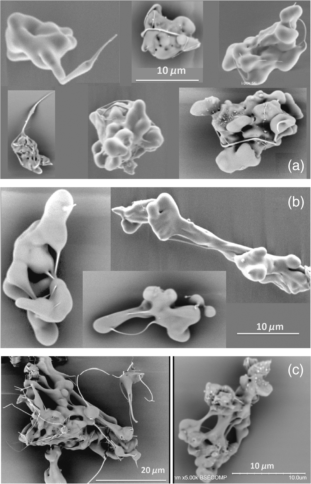 Type 2c particles are ejected at the latter stage of phase 3. As a result of the lower dynamic pressure they encounter during propagation in air (as a result of their lower speed) and their higher viscosity (lower temperature), type 2c particles better maintain the structure of the particle at the time of separation from the superheated material. Representative examples shown in Fig. 5(c) demonstrate a stretched foam-like structure. This structure may correspond to the network of bubbles and instabilities formed inside the superheated material during volume boiling. Therefore, we hypothesize that the morphology of the type 2c particles provides insight into the complex morphology of the superheated material. The structure is characterized by globules ( to in diameter) and interconnecting columns ( to in diameter). Multiple fibers originating from different parts of the particle are commonly observed. It must be noted that the formation of such larger type 2c particles (20 to in diameter) was enabled by the relatively large pool of superheated material (larger than the particles) under the excitation conditions used in the experiments. Such particles may not be observed in damage sites generated under ICF-class laser operational conditions. However, they provide insight into the possible structure of the superheated material at the later stage of phase 3. Figure 5(b) shows representative examples of type 2b particles. They are smaller in size and appear to be segments of type 2c particles. Specifically, the structure of globules and columns is preserved but not the foam-like appearance. In addition, globules interconnected with fibers indicate the separation from a more-complex and larger structure. Arguably, the smaller size of type 2b particles is caused by the higher pressure and lower viscosity at the time of their ejection. We therefore assume that the ejection took place during midstage of phase 3. The fact that the globules and columns of the type 2b particles are still largely preserved indicates that the dynamic pressure (arising from their ejection speed) applied on them was still sufficiently low and did not cause significant deformation during their flight (in air) to the collector sample. The type 2a particles are generated early during phase 3 of the material ejection process when the temperature of the superheated material is higher (and viscosity is lower) compared to the latter stages of phase 3 when types 2b and 2c particles are ejected. In addition, the speed of the particles is higher. The combination of lower viscosity and higher dynamic pressure causes deformation of the particles during their flight in air. Typical examples of type 2a particles are shown in Fig. 5(a). They are observed to have a complex outline with clearly visible globules but the foam-like structure has been lost. Dangling and interconnecting fibers are also commonly observed and are often wrapped around the particle, a signature that the particles were rotating during their flight. We propose that the higher dynamic pressure applied on type 2a particles causes modification of their shape, and in particular, the collapse of the foam-like structure observed in the lower-speed types 2b and 2c particles. The size of the globules is also slightly smaller compared to the corresponding size of types 2b and 2c particles, which is expected based on the lower viscosity of the superheated material earlier in phase 3 compared to the latter stages (when types 2b and 2c particles are generated). Indeed, as the periodicity of the structure of the superheated material during volume boiling (phase 3) may depend on the viscosity, the diameter of the globules (between 2 and ) and the interconnecting columns (between 0.5 and ) provides a signature of the changing viscosity. Types 3 and 4 particles arise from mechanical damage of the cold material surrounding the superheated region. The ejection speed of types 3 and 4 particles is less than . The initial pressure inside the superheated material is of the order of 10 GPa, which causes axial compressive stress on the surrounding cold material volume. The rarefaction wave that follows the shock wave causes a reduction of the medium’s density, leading to circumferential (hoop) stress that supports the generation of radial cracks.19 Release of the compressive stress eventually leads to axial tensile stress as the compressed material relaxes. This supports the generation of lateral cracks. This mechanism causes pulverization of the surrounding material volume, leading to the generation of fragmentation particles. The particles are ejected by stored stress and are released as the superheated material volume relaxes. The difference between types 3 and 4 particles is the origination location. Type 3 particles originate at the boundary of the liquid material pool; therefore, they contain molten material remnants. This aspect is illustrated in the representative images shown in Fig. 6. Fibers with diameters between and 300 nm are commonly observed, indicating that the separation took place while the material was still in the liquid phase. Type 4 particles originate from the adjoining pulverized region. Typical examples are represented by the SEM images shown in Fig. 7. Classic cleaved surfaces along with fragments that contained the polished surface of the substrate (example on right-hand side in Fig. 7) represent the typical morphology of type 4 particles observed. The proposed relaxation mechanism via sequential ejection of particles of different types was based on the distinct morphologies of the particles and the time-resolved images of the ejection process showing that the particles ejected early are faster and smaller, while particles that appear mechanically damaged fragments have the lowest speeds of ejection and trail the other particles.17,18 Additional evidence supporting the proposed sequence of particle ejection was obtained by further examination of larger-sized types 3 and 4 particles. Since the aerodynamic force acting opposite to the movement of the particles (drag) during propagation in air depends on the cross-sectional area of the particle, the deceleration of the ejected particles strongly depends on their size (surface to volume ratio) with smaller particles exhibiting higher deceleration (as the inverse of their radius for spherical particles). As a result, larger particles ejected at later times can catch up (during their flight in air) to smaller particles that were originally ejected earlier with higher speed. This is demonstrated in the typical examples shown in Fig. 8, where smaller particles visualized under SEM imaging are seen attached to the larger particles. Specifically, Fig. 8(a) shows, at higher magnification, a section of a type 3 particle, revealing that there are a large number of type 1 particles attached on its surface. These particles have the appearance of droplets, with a fiber “tail” and platelets having diameter of the order of or less. It is characteristic that type 1 (and, less commonly, type 2 particles, but never type 4 particles) are observed to attach to type 3 particles. This indicates that type 4 particles are ejected after the ejection of type 3 particles. On the other hand, it is commonly observed that larger type 4 particles have smaller type 4 particles attached to their surface, as well as type 1 particles. A typical example is shown in Fig. 8(b), where a section of a type 4 particle is shown. It is observed that on the cleaved surface of the particle there are smaller type 4 particles attached, having lateral dimensions of the order of 2 to . In addition, type 1 particles having diameter of the order of or less are also observed attached to the surface of the type 4 particle shown. This indicates that type 4 particles are ejected late in the process, following the ejection of all other types of particles. This analysis further supports the proposed relaxation mechanism via sequential ejection of different types of particles during the relaxation of the superheated and surrounding affected material. Fig. 8SEM images of larger particles suggest that smaller particles were attached during propagation in air. (a) A section of a type 3 particle containing a large number of type 1 particles attached on its surface. (b) A cleaved surface of a type 4 particle containing smaller type 1 and 4 particles attached. Additional details are provided in the text. 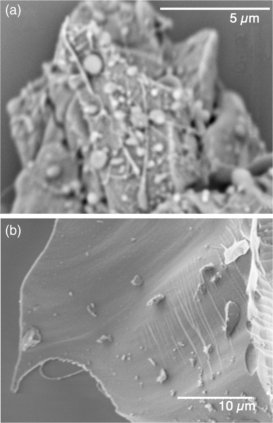 Although particles were typically observed to maintain their initial structure after impact on the collector substrate, areas on the surface of the collector sample that resembled a secondary debris zone around an impact location of a larger ejected particle were also frequently observed. A typical example is shown in Fig. 9(a), where three impact locations (denoted by 1 to 3) are included. The appearance of impact location 1 suggests that the particle broke into smaller pieces after colliding on the surface of the collector sample, creating secondary smaller particles in close proximity. This suggests that the original particle was still “soft” at the time of impact, allowing it to break into smaller pieces because of the exerted impact pressure. Similarly, locations 2 and 3 also exhibit debris fields; however, the original particles that broke upon impact appear to have been larger, as indicated by the larger number of secondary particles surrounding these locations. A higher-magnification image of location 3 is shown in Fig. 9(b). This image [rotated by 45 deg with respect to that shown in Fig. 9(a)] indicates significant changes in the substrate (denoted by 4 to 6). Specifically, feature 4 is a depression on the surface that was created by the removal of a flake. The image shows additional particles attached to the exposed surface of feature 4. This is assigned to additional particles that deposited during the multishot particle-collection experiment after the removal of the flake. Feature 5 shows the presence of a crack whereas feature 6 shows a flake still attached but raised with respect to the surface of the collector sample. There is also rubble material protruding from the surface within a radius of the order of originating from the impact particle. These results suggest that ejected particles can cause mechanical damage on the collector substrate because of the impact pressure. Fig. 9SEM images of the impact location of particles on the collector sample. (a) Lower-magnification image showing three impact locations (denoted by 1 to 3). (b) Higher-magnification images of impact location 3 showing features (4 to 6) associated with mechanical damage of the substrate. 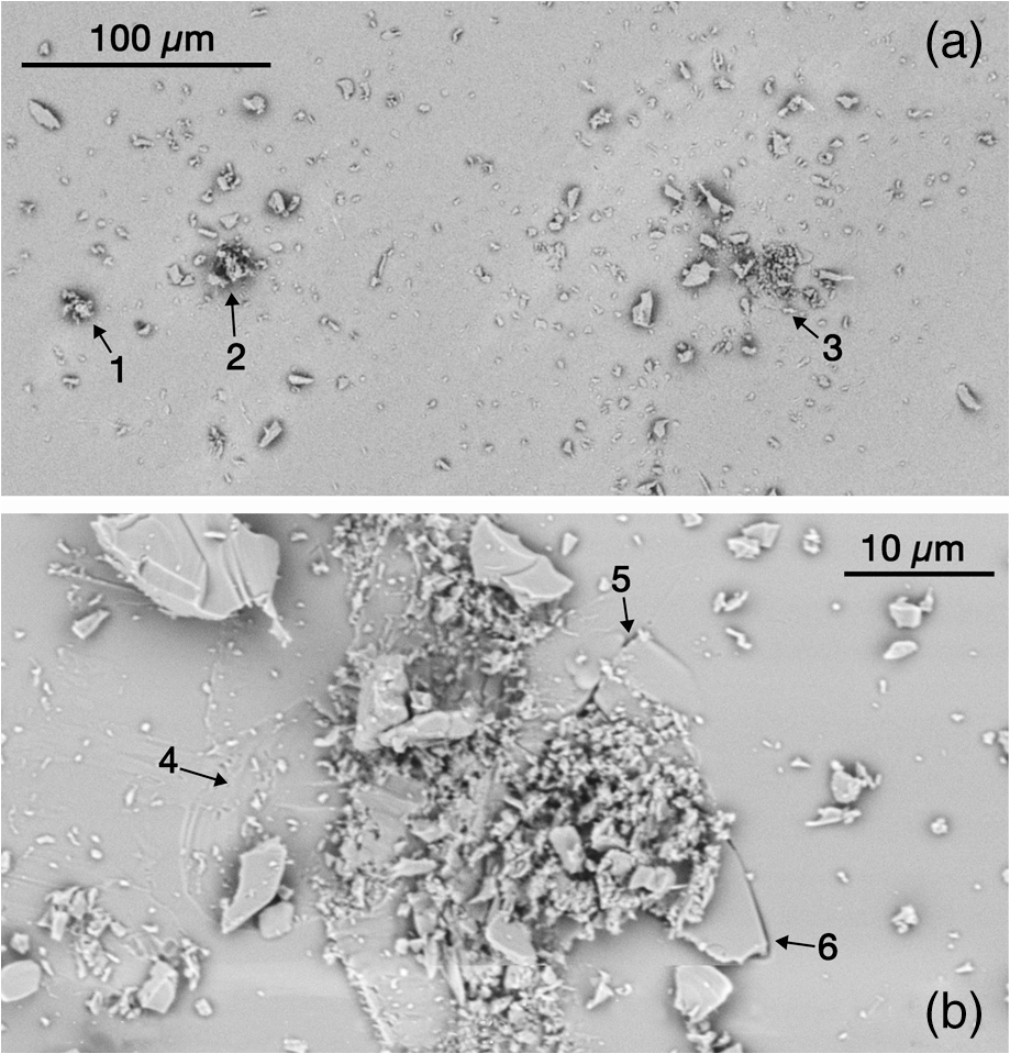 These secondary debris fields surrounding some of the impact locations are comprised of smaller fragments that do not resemble the appearance of any type of the particles discussed above. Instead, they encompass sharp edges and rough surfaces. We postulate that these fragments result from the disintegration of larger type 2 particles having higher speed while their surface has nearly solidified at the time of impact. This causes the fragmentation of the particle upon impact and the dispersion of fragments. Additional experiments were performed to further investigate the damage sustained on the collector substrate caused by the impact of the ejected particles. First, we attempted to remove the weakly attached particles by using compressed air; this step was partially successful in cleaning most, but not all, of the particles visible to the naked eye. We subsequently used drag wiping with methanol multiple times until no further removal of visible features was possible. A high-resolution optical image of the entire collector sample was performed using bright- and dark-field illumination. Figure 10(a) shows the dark-field image of the collector sample containing the nearly circular, -diameter area where the particle jet was intercepted (shown with dashed line). It can be appreciated that the vast majority of the scattering centers, associated with modification of the surface of the collector substrate, are within the circular area where the particle jet was intercepted. This indicates that the permanent modification of the substrate is associated with the impact of the high-speed ejected particles. Figure 10(b) shows a higher-resolution bright-field image near the center of the image shown in Fig. 10(a) revealing various morphologies of the induced modification/damage of the collector substrate. Fig. 10(a) Dark-field image of the collector sample (following cleaning by drag wiping with methanol multiple times) containing the nearly circular area where the particle jet was intercepted (dashed line). (b) A higher-resolution, bright-field image near the center of the image shown in (a) revealing various morphologies of the induced modification/damage of the collector substrate. 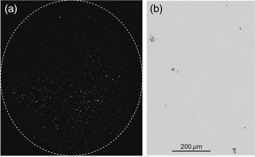 To better elucidate the morphologies of the induced modification of the collector substrate, the sample was also imaged using electron scanning microscopy. Examination of multiple sites suggests that there are two general types of modifications. These are (a) cracking usually accompanied by removal of fragments and (b) molten glass remnants attached on the surface. Characteristics example are shown in Fig. 11. Specifically, Fig. 11(a) shows an impact site where removal of material fragments (flakes) around the impact location is evident. This indicates that the pressure generated by the collision of the ejected particle on the collector substrate exceeded its fracture threshold. Figures 11(b) and 11(d) exemplify the second impact damage morphology associated with the fusion and tight attachment of at least a portion of the particle on the substrate. Figure 11(c) shows that the cleaning process removed the particle (except a small section) but the substrate has multiple scars that do not appear to be from the removal of a chip [such as that shown in Fig. 11(a)]. We hypothesize that the particle that created this site was relatively cold and as a result, the fusion with the substrate was minimal; this enabled the particle removal during wipe cleaning accompanied by additional shallow sections of the substrate at the points of partial fusion. 4.DiscussionThis study provides direct information regarding the morphology of the generated particles. In turn, the morphologies of the produced particles provide a fingerprint of the state of the material during its relaxation. The shapes and sizes of the particles correlate to their location and time of ejection while the shape of the molten particles correlates with the transient viscosity and pressure of the superheated material. The “frozen” nodular and columnar features may be related to instabilities inside the superheated material during volume boiling. Such particles are expected to be generated during laser-induced damage on silica optics used in ICF-class laser systems. The experiments were designed to generate a larger volume of superheated material. This made it possible to observe larger ejected particles deemed as type 2c particles. Such particles may not be generated during laser-induced damage initiation at ICF-class laser operational conditions. However, it is well accepted that such laser systems operate with a number of “growing” damage sites during operation. These sites absorb a sufficiently large amount of energy18 to support the formation of a larger pool of superheated material, thereby generating type 2c particles. The particles investigated in this work are ejected well after the termination of the laser pulse, and they are associated with the intrinsic response of the material to its localized superheating. It is therefore expected that the generation of these particles is independent for a wide range of excitation conditions (laser energy, wavelength, pulse duration, and excitation geometry) as demonstrated in part in Ref. 13. The dominant parameters are expected to be the spatial dimensions and the initial temperature and pressure of the superheated material volume, which, in turn, determines the relative contribution of each type of particles generated during the explosive relaxation of the material. In addition, the observed behaviors are not expected to be unique to fused silica. Instead, similar response is expected from other transparent solid-state materials with adaptations related to the individual material thermophysical and thermomechanical properties. The results also suggest that ejected particles having higher speeds can cause impact damage on adjacent optics. The presence of optical components at short separation distances is typical in ICF-class laser systems. Furthermore, the section of the laser handling the higher laser harmonics (that are more susceptible to damage initiation and damage growth) is in a reduced-pressure environment that would support the traversing of the particles from the one (damaging) optics to the neighboring optic with minimal kinetic energy loss. As a result, additional damage on the neighboring optic from impact in addition to contamination by the ejected particles is anticipated. Both of these secondary effects can lead to damage-initiation and growth sites20–22 as well as be the origin of phase objects and light-scattering centers.23 AcknowledgmentsThis work was performed under the auspices of the U.S. Department of Energy by Lawrence Livermore National Laboratory under Contract No. DE-AC52-07NA27344. ReferencesF. W. Dabby and U.-C. Peak,
“High-intensity laser-induced vaporization and explosion of solid material,”
IEEE J. Quantum Electron., 8 106
–111
(1972). http://dx.doi.org/10.1109/JQE.1972.1076937 IEJQA7 0018-9197 Google Scholar
A. Miotello and R. Kelly,
“Laser-induced phase explosion: new physical problems when a condensed phase approaches the thermodynamic critical temperature,”
Appl. Phys. A, 69 S67
–S73
(1999). http://dx.doi.org/10.1007/s003399900296 Google Scholar
N. M. Bulgakova and A. V. Bulgakov,
“Pulsed laser ablation of solids: transition from normal vaporization to phase explosion,”
Appl. Phys. A, 73 199
–208
(2001). http://dx.doi.org/10.1007/s003390000686 Google Scholar
P. Lorazo, L. J. Lewis and M. Meunier,
“Thermodynamic pathways to melting, ablation, and solidification in absorbing solids under pulsed laser irradiation,”
Phys. Rev. B, 73 134108
(2006). http://dx.doi.org/10.1103/PhysRevB.73.134108 Google Scholar
E. Leveugle et al.,
“Making molecular balloons in laser-induced explosive boiling of polymer solutions,”
Phys. Rev. Lett., 98 216101
(2007). http://dx.doi.org/10.1103/PhysRevLett.98.216101 PRLTAO 0031-9007 Google Scholar
R. F. Wood et al.,
“Dynamics of plume propagation and splitting during pulsed-laser ablation,”
Phys. Rev. Lett., 79 1571
–1574
(1997). http://dx.doi.org/10.1103/PhysRevLett.79.1571 PRLTAO 0031-9007 Google Scholar
S. S. Harilal et al.,
“Internal structure and expansion dynamics of laser ablation plumes into ambient gases,”
J. Appl. Phys., 93 2380
–2388
(2003). http://dx.doi.org/10.1063/1.1544070 JAPIAU 0021-8979 Google Scholar
Z. Chen and A. Bogaerts,
“Laser ablation of Cu and plume expansion into 1 atm ambient gas,”
J. Appl. Phys., 97 063305
(2005). http://dx.doi.org/10.1063/1.1863419 JAPIAU 0021-8979 Google Scholar
Q. Ma et al.,
“Experimental investigation of the structure and the dynamics of nanosecond laser-induced plasma in 1-atm argon ambient gas,”
Appl. Phys. Lett., 103 204101
(2013). http://dx.doi.org/10.1063/1.4829628 APPLAB 0003-6951 Google Scholar
A. Salleo et al.,
“Laser-driven formation of a high-pressure phase in amorphous silica,”
Nat. Mater., 2 796
–800
(2003). http://dx.doi.org/10.1038/nmat1013 NMAACR 1476-1122 Google Scholar
C. H. Li et al.,
“Structural modification in amorphous silica after exposure to low fluence 355 nm laser irradiation,”
Nucl. Instrum. Methods B, 269 544
–549
(2011). http://dx.doi.org/10.1016/j.nimb.2011.01.005 NIMBEU 0168-583X Google Scholar
M. J. Matthews et al.,
“Synchrotron radiation infrared microscopic study of non-bridging oxygen modes associated with laser-induced breakdown of fused silica,”
Appl. Phys. Lett., 99 151109
(2011). http://dx.doi.org/10.1063/1.3651755 APPLAB 0003-6951 Google Scholar
S. G. Demos et al.,
“Relaxation dynamics of nanosecond laser superheated material in dielectrics,”
Optica, 2 765
–772
(2015). http://dx.doi.org/10.1364/OPTICA.2.000765 Google Scholar
R. N. Raman, R. A. Negres and S. G. Demos,
“Time-resolved microscope system to image material response following localized laser energy deposition: exit surface damage in fused silica as a case example,”
Opt. Eng., 50 013602
(2011). http://dx.doi.org/10.1117/1.3526689 Google Scholar
R. N. Raman et al.,
“Characterization of ejected fused silica particles following surface breakdown with nanosecond pulses,”
Opt. Express, 20
(25), 27708
–27724
(2012). http://dx.doi.org/10.1364/OE.20.027708 OPEXFF 1094-4087 Google Scholar
R. H. Doremus,
“Viscosity of silica,”
J. Appl. Phys., 92 7619
–7629
(2002). http://dx.doi.org/10.1063/1.1515132 JAPIAU 0021-8979 Google Scholar
R. N. Raman, R. A. Negres and S. G. Demos,
“Kinetics of ejected particles during laser-induced breakdown in fused silica,”
Appl. Phys. Lett., 98 051901
(2011). http://dx.doi.org/10.1063/1.3549193 APPLAB 0003-6951 Google Scholar
S. G. Demos, R. N. Raman and R. A. Negres,
“Time-resolved imaging of processes associated with exit-surface damage growth in fused silica following exposure to nanosecond laser pulses,”
Opt. Express, 21 4875
–4888
(2013). http://dx.doi.org/10.1364/OE.21.004875 OPEXFF 1094-4087 Google Scholar
S. G. Demos et al.,
“Material response during nanosecond laser induced breakdown inside of the exit surface of fused silica,”
Laser Photonics Rev., 7 444
–452
(2013). http://dx.doi.org/10.1002/lpor.201200100 Google Scholar
R. A. Negres et al.,
“Probability of growth of small damage sites on the exit surface of fused silica optics,”
Opt. Express, 20
(12), 13030
–13039
(2012). http://dx.doi.org/10.1364/OE.20.013030 OPEXFF 1094-4087 Google Scholar
P. E. Miller et al.,
“Fracture-induced subbandgap absorption as a precursor to optical damage on fused silica surfaces,”
Opt. Lett., 35 2702
–2704
(2010). http://dx.doi.org/10.1364/OL.35.002702 OPLEDP 0146-9592 Google Scholar
R. N. Raman et al.,
“Damage on fused silica optics caused by laser ablation of surface-bound microparticles,”
Opt. Express, 24 2634
–2647
(2016). http://dx.doi.org/10.1364/OE.24.002634 OPEXFF 1094-4087 Google Scholar
M. J. Matthews et al.,
“Phase modulation and morphological evolution associated with surface-bound particle ablation,”
J. Opt. Soc. Am. B, 30 3233
–3242
(2013). http://dx.doi.org/10.1364/JOSAB.30.003233 JOBPDE 0740-3224 Google Scholar
BiographyStavros G. Demos is currently a senior scientist at the Laboratory for Laser Energetics, University of Rochester. He was previously a staff scientist at Lawrence Livermore National Laboratory for 19 years. His research interests include understanding the fundamentals and dynamics of laser energy deposition in defects structures and ensuing material transient properties and modifications. He has also been involved in the field for biomedical photonics including the development of spectroscopic microscopy and endoscopy techniques and instrumentation. |