|
|
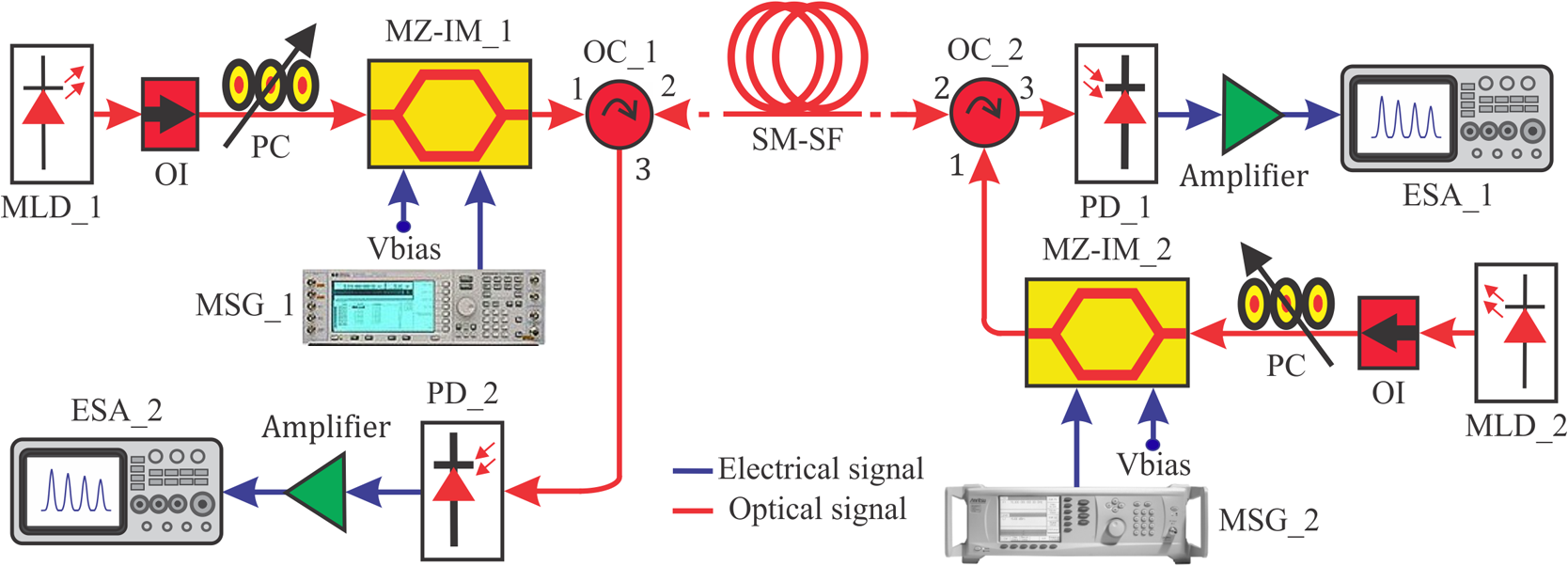
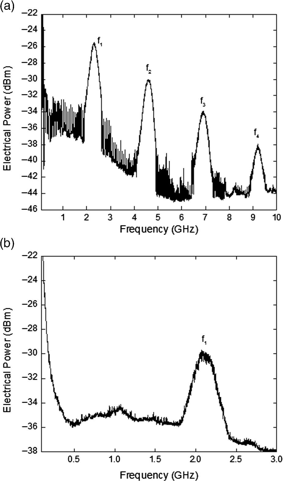
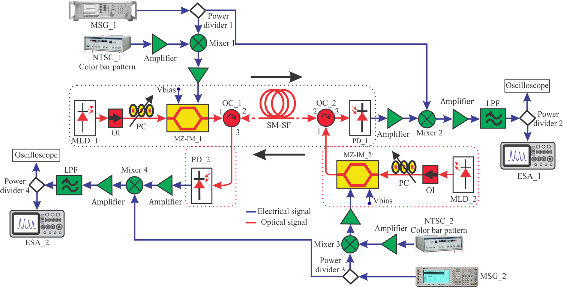
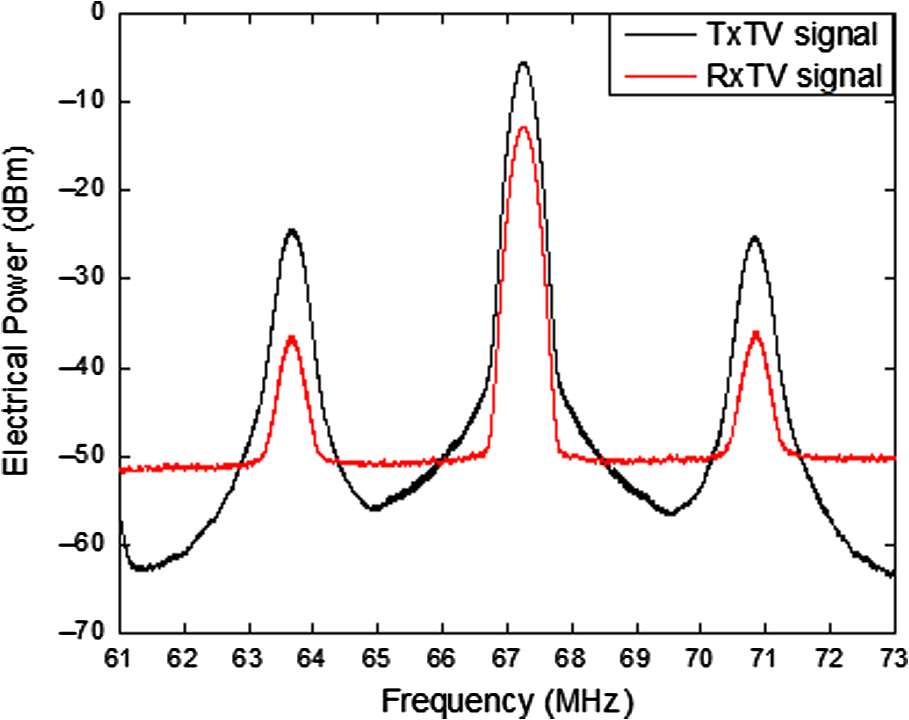
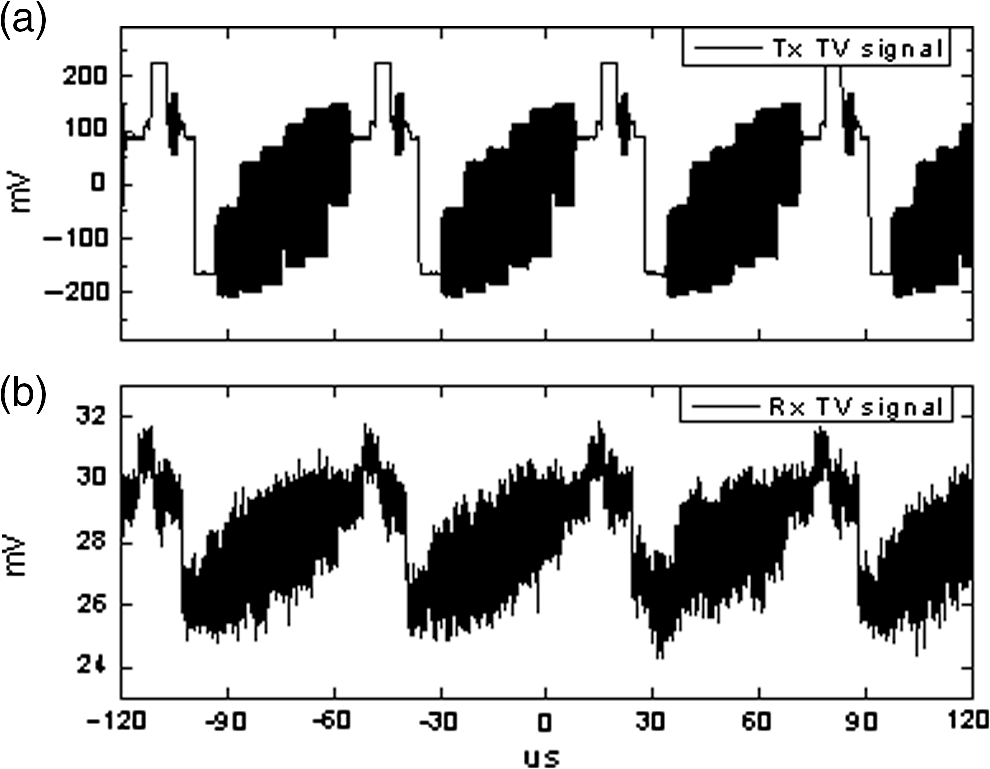
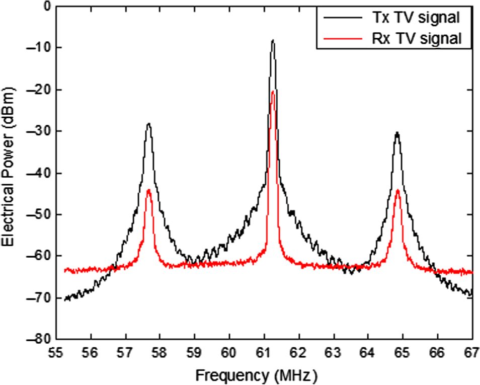
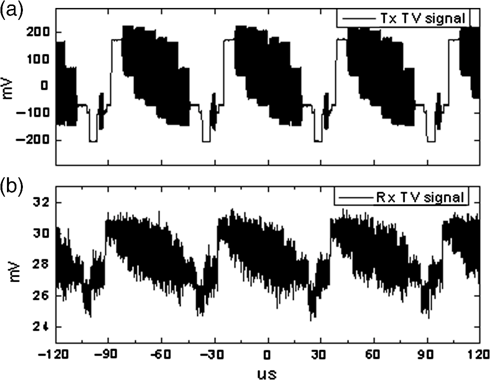
1.IntroductionCurrently, there is an increased need of more simultaneous signal-processing functions directly in the optical domain.1 A solution to this demand is the microwave photonic filters (MPFs) that allow interaction between microwave RF signals and optical signals directly in the optical domain. The advantages of MPFs are low loss, high bandwidth, immunity to electromagnetic interference, tunability, and reconfigurability2 providing a wide range of applications in network architectures, such as3 fiber-to-the-node, fiber-to-the-curb (FTTC), fiber-to-the-building, fiber-to-the-home, and radio-over-fiber.4 Considering these advantages, in the literature, there are multiple MPF architectures published. For instance, in Ref. 5, a MPF based on a distributed feedback laser and a fiber Bragg grating is described; in Ref. 6, a Sagnac loop is used; and in Ref. 7, a fiber optic of 20.70 km is employed as a delay line to obtain filtering of microwave signals. Recently, in Ref. 8 a bidirectional 10-GHz MPF architecture, as shown in Fig. 1, is proposed. Its frequency response in the range of 0.01 to 10 GHz is composed of four filtered bandpass windows centered at , , , and . Basically, these filtered microwave bandpass windows are obtained considering the free-spectral range () of a multimode laser diode (MLD), the length () of an optical fiber, and its associated chromatic dispersion parameter (). These parameters allow the central frequency () of the filtered microwave bandpass windows to be calculated by means of the relationship , where is an integer A detailed explanation of the principle of operation of the bidirectional 10-GHz MPF is given in Ref. 8. Figure 2(a) shows the frequency response recovered by photo detector 1 (PD_1) for the left-to-right direction. Due to technical limitations, as mentioned in Ref. 8, Fig. 2(b) depicts only the filtered bandpass windows centered at , which are recovered by PD_2 for the right-to-left direction. Reference 8 established the following hypothesis: “potentially the filtered bandpass windows can be used as electrical carriers to transmit services, such as video, voice, and data.” Now, the main goal of this work is to demonstrate the use of the filtered microwave bandpass window located around 2 GHz as an electrical carrier to transmit simultaneous analog TV signals of 67.25 (channel 4) and 61.25 MHz (channel 3) in both directions. Although we describe only the experiment corresponding to the filtered bandpass centered at 2 GHz, it is important to note that the other bandpass windows can potentially be used as electrical carriers. Moreover, tuning of the filtered bandpass windows can be obtained by selecting the appropriate optical parameters. At this point, it should be noted that the originality of this electro-optical system resides in the advantageous use of the chromatic dispersion parameter exhibited by the optical fiber to obtain the filtering effect. To the best of our knowledge, this is the first time that a bidirectional MPF is used in simultaneous transmission of analog TV signals. This paper is organized as follows: Sec. 2 is devoted to describing the experimental setup and showing the results that validate the bidirectional transmission of TV signals; Sec. 3 presents the main technical limitations, as well as the perspectives of future applications for this topology. 2.Experimental Setup and ResultsFigure 3 illustrates the experimental setup assembled to carry out the transmission of analog TV signals coded on the filtered microwave bandpass window located around 2 GHz in both directions. The goal is to transmit simultaneous analog TV signals of 67.25 and 61.25 MHz, from left to right and from right to left, respectively. Reviewing Fig. 3, it is clearly distinguishable that dotted boxes correspond to the bidirectional MPF architecture previously depicted in Fig. 1, and the other elements are the additional electronic equipment and radio-frequency devices. At this point, it is very important to notice that the filtered bandpass windows used as electrical carriers in the left-to-right and right-to-left directions are located at 2.31 and 2.08 GHz, respectively. This difference is justified by the use of electro-optical devices from distinct manufacturers, as is explained in Ref. 8. In the following, the procedure for the bidirectional transmission is described in detail, taking into account the direction. 2.1.Transmission of an Analog TV Signal in the Left-to-Right DirectionIn the first step, the MLDs (operated by temperature controllers to guarantee the stability of their optical parameters to thermal fluctuations) used in this experiment are optically characterized by means of an optical spectrum analyzer. For this case, MLD_1 (Thorlabs, model S1FC1550) at an optical power (OP) of 1.25 mW gives , , and . In order to avoid reflections to the source and to maximize the modulator output OP, it is necessary to use an optical isolator (OI) and a polarization controller (PC), respectively. The polarized light is injected to Mach–Zehnder intensity modulator 1 (MZ-IM_1) (Photline, model MXAN-LN-20, insertion loss of 2.7 dB, operating wavelength of 1530 to 1580 nm, and ). The microwave signal generator MSG_1 (Anritsu, model MG3692, 0.01–20.0 GHz) provides an electrical signal of 2.31 GHz at a power of 5 dBm. This signal is divided through a splitter (power divider 1); part of this electrical signal is transmitted through cable to demodulate the signal, and the rest is mixed (mixer 1) with an amplified analog National Television System Committee (NTSC_1) TV signal of 67.25 MHz. The mixed electrical signal is applied to the RF port of MZ-IM_1 in order to modulate the light emitted by MLD_1. Then, the optical output of MZ-IM_1 is launched to Port1 of an optical circulator (OC_1) passing to Port2, where it is coupled into a coil of (available in our laboratory) of single-mode standard fiber (SM-SF), which exhibits and at . At the end of the optical link, the light is injected to Port2 of OC_2 passing to Port3, which is connected to a fast PD (PD_1, MITEQ, model DR-125G-A, bandwidth of 13 GHz and ). The electrical signal delivered by PD_1 is amplified and mixed (mixer 2) with the demodulated signal to suppress the carrier signal of 2.31 GHz. Finally, after a stage of amplification and low pass filtering (LPF), the recovered analog TV signal is passed through power divider 2 and is connected to an electrical spectrum analyzer (ESA_1, Anritsu, model MS2830A-044, 9 kHz to 26.5 GHz) or to an oscilloscope (Keysight DSA V084A, 8 GHz, ). Figure 4 shows the measured electrical spectrum of the transmitted and recovered TV signals, showing a SNR of 49.66 and 37.62 dB, respectively. The time-domain waveforms of standard NTSC corresponding to the transmitted (upper) and recovered (lower) signals measured with an oscilloscope are depicted in Fig. 5. It is important to note that the optical circulators used in this experiment have the following optical specifications: wavelength range 1525 to 1610 nm, isolation , directivity , and return loss . 2.2.Transmission of an Analog TV Signal in the Right-to-Left DirectionThe optical source used is MLD_2 (Thorlabs, model LPS-1550-FC), which at an gives , , and . The description for this transmission direction is similar to the case previously described. The main differences are the use of MZ-IM_2 (JDSU, model AM-150, insertion loss of 5.0 dB, operating wavelength 1540 to 1560 nm, and ) as well as MSG_2, whose main limitation is its frequency range of operation (Agilent, model E4425B, 250 kHz to 3.0 GHz). Thus, the light issued from MLD_2 passes through the OI and the PC and is injected to MZ-IM_2. The electrical signal at the output of MSG_2 is divided (power divider 3) in order to feed MZ-IM_2 and to generate the demodulated signal. The resulting mixed (mixer 3) electrical signal between MSG_2 of 2.08 GHz () and NTCS_2 TV signal of 61.25 MHz is connected in the RF port of MZ-IM_2. The modulated optical signal at the output of MZ-IM_2 is launched to Port1 of OC_2 passing to Port2, where it is connected into the bobbin of SM-SF for its return in the left direction. Then the light is attached to Port2 of OC_1 passing to Port3 in order to be launched to PD_2 (MITEQ, model DR-125G-A, bandwidth of 13 GHz and ). The recovered electrical signal at the output of PD_2 is amplified and passed onto an electrical mixer (mixer 4) in order to be added to an electrical carrier of 2.08 GHz that is generated by MSG_2 and transmitted through cable. Finally, after an amplifier and a LPF, the recovered analog TV signal is connected to power divider 4, where it can be attached to ESA_2 or to an oscilloscope. Figure 6 displays the spectrum of the TV signal of 61.25 MHz transmitted and recovered, with a power level of () and (), respectively. Figure 7 depicts the time-domain waveforms of standard NTSC obtained through an oscilloscope, where upper and lower traces correspond to the transmitted and recovered signals. 3.ConclusionsWe have successfully demonstrated a practical application of a bidirectional MPF to transmit simultaneous analog TV signals coded on filtered microwave bandpass windows. Through a series of experiments, the feasibility of the hypothesis posed at the beginning of this work was successfully validated. In particular, the analog TV signals of 67.25 and 61.25 MHz were coded on the filtered microwave bandpass windows centered at 2.31 and 2.08 GHz. Acceptable SNR values were obtained for each case, as is reported in Ref. 9. The key interest of this bidirectional MPF resides in the advantageous use of the chromatic dispersion parameter associated with the optical fiber to obtain the filtering effect. Moreover, the filtered microwave bandpass windows are used as electrical carriers. Undoubtedly, this experimental scheme can be exploited using the other filtered microwave bandpass windows, that is, , , and . Note that the use of different fiber lengths allows tuning the filtered microwave bandpass windows that obey the relationship . Unfortunately, due to the unavailability of different lengths () of optical fibers, this last affirmation was not corroborated. Future work will be devoted to testing the proposed bidirectional MPF for different optical fiber lengths in order to use different filtered microwave bandpass windows as electrical carriers. We also anticipate that a full exploitation of the proposed bidirectional MPF can be achieved by the use of a digital pattern generator in order to transmit digital signals and measure parameters, such as bit error rate and eye diagram penalties. The good results obtained in this experiment potentially point to using this topology in access networks where the distance is . In summary, the proposed electro-optical architecture here reported demonstrated a good robustness and stability for the simultaneous transmission of analog TV signals. AcknowledgmentsThis work was supported by the Mexican Consejo Nacional de Ciencia y Tecnología (CONACyT), Project No. 154691. One of the authors, A. G. Correa-Mena, wishes to thank the CONACyT for the student scholarship number 335148. ReferencesJ. Capmany et al.,
“Microwave photonic signal processing,”
J. Lightwave Technol., 31 571
–586
(2013). http://dx.doi.org/10.1109/JLT.2012.2222348 Google Scholar
J. Capmany, B. Ortega and D. Pastor,
“A tutorial on microwave photonic filters,”
J. Lightwave Technol., 24 201
–229
(2006). http://dx.doi.org/10.1109/JLT.2005.860478 Google Scholar
Z. Jia, J. Yu and G. Chang,
“A full-duplex radio-over-fiber system based on optical carrier suppression and reuse,”
IEEE Photonics Technol. Lett., 18 1726
–1728
(2006). http://dx.doi.org/10.1109/LPT.2006.879946 Google Scholar
S. Li et al.,
“A novel tunable all-optical incoherent negative tap fiber optic transversal filter, based on a DFB laser diode and fiber Bragg gratings,”
IEEE Photonics Technol. Lett., 12 1207
–1209
(2000). http://dx.doi.org/10.1109/68.874237 IPTLEL 1041-1135 Google Scholar
Y. Gao et al.,
“Novel tunable microwave photonic notch filter using a coupler based Sagnac loop,”
Opt. Commun., 281 1476
–1479
(2007). http://dx.doi.org/10.1016/j.optcom.2007.11.064 OPCOB8 0030-4018 Google Scholar
I. E. Zaldívar-Huerta et al.,
“Experimental transmission in a fiber-radio system using a microwave photonic filter at 2.8 GHz,”
IEICE Electron. Express, 10 1
–10
(2013). http://dx.doi.org/10.1587/elex.10.20130028 Google Scholar
I. E. Zaldívar-Huerta et al.,
“Demonstration and experimental evaluation of a bi-directional 10-GHz microwave photonic filter,”
Opt. Laser Technol., 83 76
–80
(2016). http://dx.doi.org/10.1016/j.optlastec.2016.03.023 Google Scholar
M. Kowalczyk and J. Siuzdak,
“Multi-channel AM video transmission beyond the baseband of multimode fiber,”
Microwave Opt. Technol. Lett., 52 435
–438
(2009). http://dx.doi.org/10.1002/(ISSN)1098-2760 MOTLEO 0895-2477 Google Scholar
BiographyAna Gabriela Correa-Mena received her BS degree in electronics and telecommunications engineering from the Universidad Tecnica Particular de Loja (Ecuador) in 2008 and her MS degree in electrical engineering from Pontifícia Universidade Católica do Rio de Janeiro (Brazil) in 2013. She is currently a PhD student in electronics from the Instituto Nacional de Astrofísica, Óptica y Electrónica (INAOE) (México). Her areas of research are optical fiber communication systems and microwave photonics. She is an IEEE member. Ignacio E. Zaldivar-Huerta received his BS degree in electronics engineering from the Universidad Autónoma de Puebla (México) in 1992, his MS degree in microelectronics from INAOE (México) in 1995, and his PhD degree in sciences for engineering from the Université de Franche-Comté (France) in 2001. Since 2002, he has been with the Department of Electronics of the INAOE. His research interests are optical fiber communication systems and electro-optic devices. He is an SPIE and IEEE member. José Humberto Abril-García received his BS degree in computer systems engineering in 2003 and his MS degree in computer science with a specialty in software engineering in 2008 from Instituto Tecnológico de Hermosillo, México. He is currently working toward his PhD degree at the Universidad de Sonora, México. His current research interests include communication systems, microwave, and systems simulations. Alejandro García-Juárez received his BS degree in electronics engineering from Universidad Autónoma de Puebla, México, in 1998 and his MS and PhD degrees in optics with a specialty in optoelectronic systems from INAOE (México) in 1999 and 2005, respectively. He is currently a titular professor–researcher with the Department of Research in Physics at the Universidad de Sonora, México. His current research interests are primarily in optical fiber communication systems, microwave photonics, and hybrid wireless visible light communication systems. Alicia Vera-Marquina received her BS degree in electronics engineering from the Universidad Autónoma de Puebla, México, in 1994 and her MS and PhD degrees in optics from INAOE (México) in 1997 and 2001, respectively. She has currently a researcher with the Department of Physics at the Universidad de Sonora, México. Since 2006, she has been a member of SPIE. Her research fields are digital optical processing, silicon-based optoelectronics, and electronic device design. |