|
|
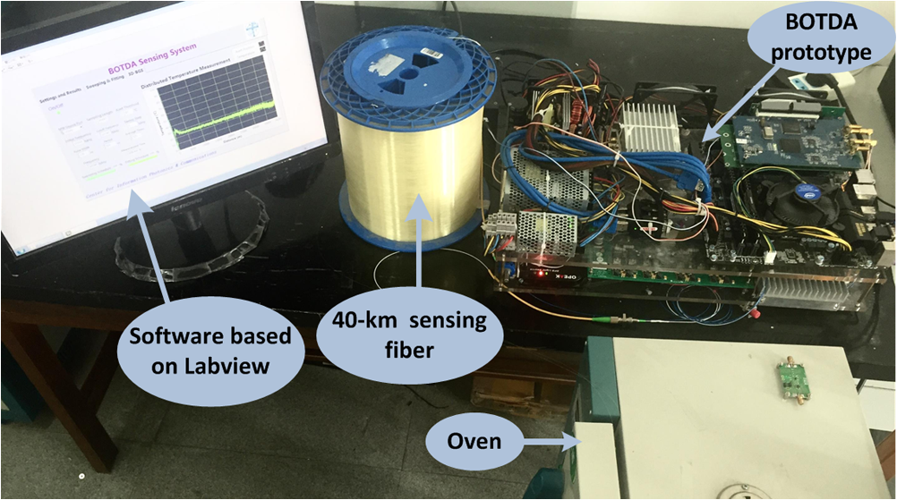
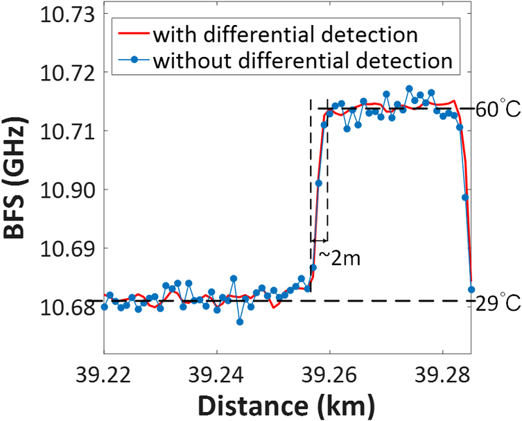
1.IntroductionDistributed optical fiber sensors based on Brillouin scattering have attracted widespread attention because of their characteristic abilities to achieve high-performance strain and temperature measurements over long distances.1–3 Among these Brillouin fiber sensor techniques, the Brillouin optical time-domain analysis (BOTDA) based on stimulated Brillouin scattering (SBS) exploits the dependence of the BFS parameter on strain and temperature, achieving highly accurate measurements over distances of more than several tens of kilometers.4,5 Aiming for higher measurement accuracy, longer sensing distance, and higher spatial resolution, many efforts such as pulse coding, Raman amplification, and frequency comb have been devoted to improve the signal-to-noise ratio (SNR) and reduce measurement time of the BOTDA sensors.6–9 Recently, coherent detection as a new method has been proposed, in which a local light beat and a probe light beam propagate through a photodetector (PD) by generating a GHz carrier to carry the Brillouin gain spectrum (BGS), resulting in significant SNR improvement ( typically) because of strong baseband noise perturbation reduction.10 To simultaneously generate local light and probe light in a coherent BOTDA sensor, double-sideband (DSB), phase modulation (PM), and intensity modulation (IM) are normally used. However, DSB modulation is very sensitive to chromatic dispersion (CD) of the sensing fiber, causing PM–IM conversion and power fading, and further introducing crosstalk in the measured BGS.11–14 Recently, we have proposed a coherent BOTDA sensing scheme with single-sideband (SSB) modulation to reduce the effect of CD.15 By taking advantage of this approach, CD can be suppressed significantly. In addition, a LogD instead of an inphase/quadrature demodulator is applied in the proposed scheme. As normally used in coherent BOTDA sensors, the LogD not only can reduce half of the measurement time but also can cancel BGS distortion caused by phase jitter. Thus, this scheme is promising for prototype integration because of its high stabilities and low complexities. Nevertheless, the generated BOTDA time trace in this scheme is normally composed of an ultrahigh level of the DC component (hundreds of millivolts typically) added to a periodic and ultralow level of Brillouin gain signal (several millivolts typically). To reconstruct the BGS from a weak Brillouin gain signal, a data acquisition (DAQ) card should have an adjustable measurement range and vertical DC offset, making the DAQ process time-consuming, unstable, and expensive. Therefore, to realize precise Brillouin gain signal acquisition with a DAQ card that has a fixed measurement range and DC offset, the ultrahigh DC component must be canceled and the weak Brillouin gain signal should be amplified to suitable amplitude. Otherwise, the amplifier used in the signal amplification (SA) circuit may easily reach the saturation state of the DAQ card because of the ultrahigh level of the DC component. In this paper, a new method is proposed to remove the DC component dynamically. A microwave signal with tunable frequencies and another equal-power microwave signal at a fixed frequency are used to modulate the laser source light and to generate the probe light and reference light, respectively. Only the probe light can sweep the Brillouin gain region, while the reference light is out of the Brillouin gain region. Subsequently, the beat note signal between the local light and probe light can carry Brillouin gain information. However, the beat note signal between the local light and the reference light has no Brillouin gain. Then, the powers of the local light and probe light are detected by two LogDs, respectively, after frequency downconversion. The detected signals are sent to a differential amplifier, and the excess DC component can be removed to obtain the “pure” Brillouin gain signal, which is further amplified by the SA circuit. The SNR of the weak Brillouin gain signal has been enhanced from (i.e., without differential amplification) to (i.e., with differential amplification). Moreover, obvious quantization errors are avoided. Finally, a BFS accuracy of is obtained at the end of a 40-km sensing fiber. 2.Detection PrincipleAs mentioned above, a LogD has been employed in our SSB IM coherent BOTDA sensor to reduce measurement time and overcome the effect of phase jitter. (Detailed theoretical analysis of this mechanism is expatiated in Ref. 14.) However, the ultrahigh-level DC component always exists in the time trace and limits SA of the weak Brillouin gain signal. For the purpose of eliminating the excessive DC component, we propose a differential detection method based on the SSB probe light, as shown in Fig. 1. Two microwave signals with different frequencies are generated to modulate the laser source light. Then, a reference light and a probe light are set at the same power. However, unlike the probe light that sweeps the Brillouin gain region of the pulsed pump light, the reference light is out of the Brillouin gain region. Thus, the intensity of the beat note signal between the local light and reference light (i.e., ) is the same as the DC component, i.e., the intensity of the beat note signal between the local light and the probe light (i.e., ) in the absence of Brillouin gain. By further sending the envelopes (obtained through the two LogDs) of these two signals to a differential amplifier, the DC component can be dynamically canceled and the weak Brillouin signal can be obtained by the DAQ card. More detailed analysis will be presented in the following paragraphs. Fig. 1Principle of differential detection. (a) Schematic diagram of the differential detection for coherent BOTDA sensor based on SSB probe light, where PD and LogD denote photodetector and logarithmic detector, respectively. (b) Frequency spectrum and waveform in the probe and detection process, where is the frequency of laser source light (i.e., local light), is the frequency of pulsed pump light with a 200 MHz frequency upshift to the local light, and are the frequency of the generated microwave signals to modulate the EOM, is the output voltage of the PD at the frequency of , is the output voltage of the PD at the frequency of , and is the output voltage of the differential amplifier.  As shown in Fig. 1(a), the source light (i.e., ) generated by the laser is split into two beams; one of the beams (i.e., signal ) is modulated by an acousto-optic modulator (AOM) to generate the pump pulsed light [i.e., or signal in Fig. 1(b)] with a 200 MHz optical frequency upshift [Fig. 1(b)], while the other beam (i.e., signal ) is modulated by an electro-optic modulator (EOM) to realize SSB modulation. Two microwave signals with different frequencies within (i.e., ) and out of (i.e., ) the BGS range [Fig. 1(b)] are generated to modulate the EOM. Because of the SSB modulation, signal consists of a carrier frequency of (i.e., the local light) and sideband frequencies including (i.e., the probe light) and (i.e., the reference light). At the output of the circulator before the PD, the optical field is where , is the BFS, and are the complex amplitudes of the local light and probe light, respectively, is the amount of Brillouin gain centered at the frequency , is the phase shift of Brillouin gain, is the local Brillouin gain, and is the Brillouin linewidth. The output voltage of the PD at the frequency [i.e., signal in Fig. 1(b)] is where and are the sensitivity and resistance of the PD, respectively. The output voltage of the PD at the frequency [i.e., signal in Fig. 1(b)] is The signal is sent to a LogD1 to reconstruct the BGS and decode the BFS. After amplitude normalization, the output voltage of LogD1 [i.e., signal in Fig. 1(b)] can be written as where is the conversion coefficient between the input power and the output voltage of LogD1. The first term of Eq. (4) is the DC component denoted by , i.e., , and the second term is the Brillouin gain signal denoted by , i.e., . The signal should be precisely sampled to reconstruct the BGS for the sensing fiber. Unfortunately, its amplitude is extremely weak, and thus, signal should be amplified with high gain to ensure that signal is strong enough to be sampled by the DAQ card without quantization errors. However, signal at the high level of hundreds of millivolts typically prohibits the amplification process because the amplifier may easily reach its saturation state. To remove the DC component, signal is sent to another LogD2. The output voltage of LogD2 [i.e., signal in Fig. 1(b)] after amplitude normalization can be written as The signals and are sent to a differential amplifier with a gain of . Then, the signal [signal in Fig. 1(b)] can be expressed as Thus, the DC component is almost removed and the weak signal can be amplified, resulting in more accurate DAQ.3.Experimental SetupFigure 2 shows the experimental configuration. A tunable distributed feedback laser with a center wavelength of 1549 nm and peak output power of 10 dBm was employed as the optical source. The laser source light was divided into two branches by a 50:50 optical coupler. One of the branches was modulated by an AOM with an extinction ratio of 50 dB to generate the pulsed pump light with a peak power of 18 dBm after being sent to an erbium-doped fiber amplifier. Before being sent to the sensing fiber, a polarization scrambler before the circulator was utilized to alleviate polarization-dependent fluctuations for the Brillouin effect between the pump and probe signals. Fig. 2Experimental setup of the proposed coherent BOTDA sensor with DC component cancellation (path a), while path b shows the case without DC compensation. EDFA, erbium-doped fiber amplifier; PS, polarization scrambler; VCO, voltage-controlled oscillator; and BPF, bandpass filter. 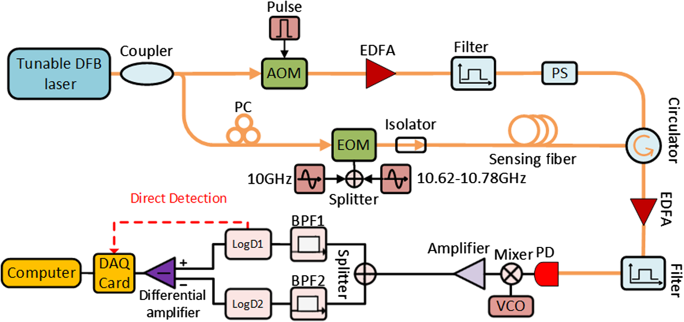 The other branch was first modulated by an intensity EOM that biased at the quadrature point and is driven by two microwave sources. The corresponding two upper optical sidebands were filtered out by a fiber Bragg grating to realize SSB modulation, and the remaining two lower optical sidebands and laser source light worked as the probe light, reference light, and local light, respectively [Fig. 1(b)]. One of the microwave sources (i.e., ) was tuned from 10.62 to 10.78 GHz with 2-MHz step to ensure that the probe light could sweep the Brillouin gain region, and the other one (i.e., ) was fixed at 10 GHz to ensure that the reference light was out of the Brillouin gain region. The powers of the local light, probe light, and reference light were 0, , and , respectively. After interacting with the pump light, all of the probe light, reference light, and local light were sent to the PD. The PD output signals (i.e., 10, 10.62 to 10.78 GHz) were frequency down-converted to intermediate signals (i.e., 200, 820 to 980 MHz) through a mixer, whose local signal was generated by a voltage-controlled oscillator at 9.8 GHz output frequency. Then, a splitter was employed to split the intermediate signals into two paths, and the 200, 820 to 980 MHz signals were selected by bandpass filters BPF1 and BPF2, and decoded by LogD1 and LogD2, respectively. The decoded signals were sent to the differential amplifier to remove the DC component and to amplify the weak Brillouin signal. Finally, the amplified Brillouin signal was sampled, averaged, and stored by a DAQ card with sampling rate and 12-bit resolution. The stored data were further processed by a computer. The prototype based on the proposed scheme is shown in Fig. 3. A single-mode fiber with a BFS of 10.68 GHz at room temperature was used as the sensing fiber, and a fiber at its end was placed in the oven for heating. The LogDs used (Model AD8317) had a responding time of and a demodulation bandwidth of , which could ensure a spatial resolution of . 4.Results and Discussions4.1.Measurement of the Long-Distance FiberTo verify the validity of differential detection, a sensing fiber was tested in the laboratory at room temperature (29°C). The width of the modulated optical pulse was 25 ns with a period of . At each sweep frequency point, a 4000 times average was implemented by the DAQ card to improve the SNR. Moreover, a comparative experiment was also conducted without using the differential detection (i.e., path bin Fig. 2). Figure 4 shows the measured Brillouin time traces for a sensing fiber at a sweeping frequency of 10.68 GHz. In the case without DC cancellation, as shown in Fig. 4(a), the measured Brillouin time trace exhibits a shape of “stairs,” which was caused by a significantly large quantization error. Even worse, because of the large DC component (), it was impossible to amplify the weak Brillouin signal to reduce the quantization error. However, in the case with DC cancellation, as shown in Fig. 4(b), times amplification can be used to amplify the weak Brillouin gain signal after the DC component elimination, i.e., the effective Brillouin signal was amplified from to , resulting in obvious quantization error reduction. Fig. 4Measured BOTDA time traces (a) without DC cancellation and (b) with DC cancellation along sensing fiber at the sweeping frequency of 10.68 GHz. 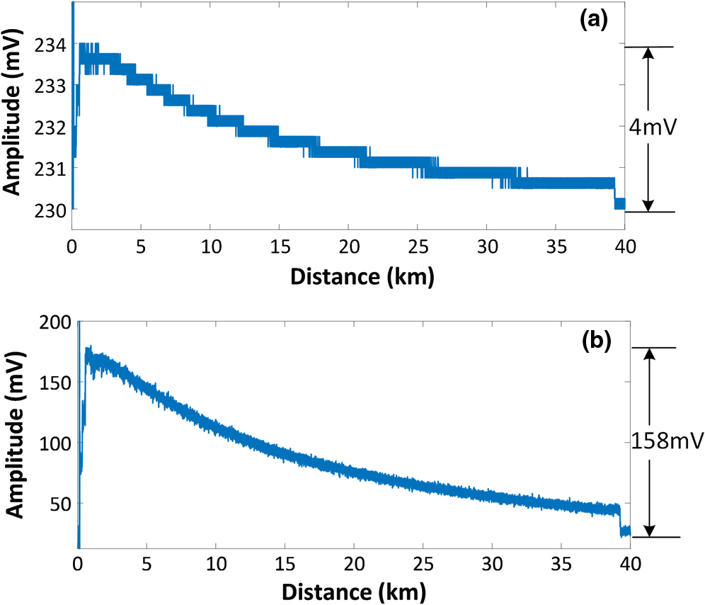 Note that there is still a small DC component (about 25 mV) as shown in Fig. 4(b). This DC component is caused by many factors: (1) the power mismatch between the fixed microwave signals (for reference signal generation) and the tunable microwave signals (for probe signal generation), the powers of the tunable microwave signals cannot keep fixed at different frequencies due to the output power ripples of the microwave signal generator, so there normally exists power mismatch between these two microwave signals; (2) response difference of the EOM, PD, and LogD at different frequencies; and (3) the inherent unbalance of the differential operational amplifier. The remaining DC component can be further decreased by using a microwave signal generator with flatter power output, by using EOM, PD, and LogDs with flatter response and by choosing a differential operational amplifier with reduced inherent unbalance. To quantify the SNR enhancement, after subtracting the DC component in the measured BOTDA time traces, we calculated the SNR for each trace using the equation where is the amplitude of the BOTDA signal when the Brillouin gain is minimum (at the end of the sensing fiber) and is the variance of the noise floor in the BOTDA time trace.14 The result showed that the SNR is enhanced from to .Figure 5 shows the measured BGS at the 2000 and 39,250 m distances without and with differential amplification and their Lorentz fitting curves. In the case with differential amplification, the measured BGS (i.e., blue lines) can match their fit cures (i.e., red lines) at both the near-fiber end (e.g., 2000 m) and far-fiber end (e.g., 39,250 m). However, in the case without differential amplification, the blue lines cannot match well with the red lines, especially at the far-fiber end, where evident BGS distortion and broadening were observed. 4.2.Temperature Measurement at Far-Fiber EndFigure 6 shows the decoded BFS at the far-fiber end from 39,220 to 39,285 m. A testing fiber at the end was placed in an oven and heated up to 60°C, while the rest of the sensing fiber was at room temperature (29°C). The spatial resolution has been estimated using the 10% to 90% rising edge of the decoded BFS to be .16 In addition, the measured BFS in the case with differential detection showed less fluctuation than that in the case without differential detection, i.e., the peak-to-peak jitter decreased from 7.0 to 2.5 MHz. By calculating the standard deviation of the BFS, we found the frequency accuracies without and with differential detection are 1.9 and 0.8 MHz, respectively, implying that the temperature/strain measurement accuracies have been enhanced by times because of the reduced quantization error. 5.ConclusionA differential detection method based on SSB probe light was proposed to remove the DC component dynamically and improve the SNR before DAQ in a BOTDA system. The main principle is to introduce two microwave signals of different frequencies — one is amplified by SBS and the other is not — to modulate the probe beam. The excess DC component was eliminated when the two microwave signals were sent to the differential interrogation part. Therefore, the “pure” Brillouin gain signal is further amplified by the SA high gain circuit with around 40 times amplification. The measured Brillouin time trace shows that the “stairs” induced by the quantization error was canceled greatly with the differential detection scheme. The SNR is enhanced by up to . The implemented BOTDA prototype system showed that the measurement accuracy of the BFS is improved by 2.5 times from to at the end of a 40-km sensing fiber. This proposed differential detection method simplifies the system and ensures real-time signal processing, which is promising and practical for future instrument implementation based on SSB modulated BOTDA systems. AcknowledgmentsThe work was supported in part by the International Science and Technology Cooperation Program of China (No. 2014DFA11170), National Natural Science Foundation of China (No. 61475128), Key Grant Project of Chinese Ministry of Education (No. 313049), and Fundamental Research Fund for the Central Universities (No. 2682014RC22). We would also like to thank Editage ( www.editage.com) for English language editing. ReferencesT. Horiguchi et al.,
“Development of a distributed sensing technique using Brillouin scattering,”
J. Lightwave Technol., 13
(7), 1296
–1302
(1995). http://dx.doi.org/10.1109/50.400684 JLTEDG 0733-8724 Google Scholar
X. Bao and L. Chen,
“Recent progress in Brillouin scattering based fiber sensors,”
Sensors, 11
(4), 4152
–4187
(2011). http://dx.doi.org/10.3390/s110404152 SNSRES 0746-9462 Google Scholar
W. Zou, Z. He and K. Hotate,
“Experimental investigation on Brillouin scattering property in highly nonlinear photonic crystal fiber with hybrid core,”
Opt. Express, 20
(10), 11083
–11090
(2012). http://dx.doi.org/10.1364/OE.20.011083 OPEXFF 1094-4087 Google Scholar
W. Li et al.,
“Differential pulse-width pair BOTDA for high spatial resolution sensing,”
Opt. Express, 16
(26), 21616
–21625
(2008). http://dx.doi.org/10.1364/OE.16.021616 OPEXFF 1094-4087 Google Scholar
Y. Dong, X. Bao and W. Li,
“Differential Brillouin gain for improving the temperature accuracy and spatial resolution in a long-distance distributed fiber sensor,”
Appl. Opt., 48
(22), 4297
–4301
(2009). http://dx.doi.org/10.1364/AO.48.004297 APOPAI 0003-6935 Google Scholar
M. A. Soto, S. Le Floch and L. Thévenaz,
“Bipolar optical pulse coding for performance enhancement in BOTDA sensors,”
Opt. Express, 21
(14), 16390
–16397
(2013). http://dx.doi.org/10.1364/OE.21.016390 OPEXFF 1094-4087 Google Scholar
H. Liang et al.,
“High-resolution DPP-BOTDA over 50 km LEAF using return-to-zero coded pulses,”
Opt. Lett., 35
(10), 1503
–1505
(2010). http://dx.doi.org/10.1364/OL.35.001503 OPLEDP 0146-9592 Google Scholar
X. Jia et al.,
“Experimental demonstration on 2.5-m spatial resolution and 1°C temperature uncertainty over long-distance BOTDA with combined Raman amplification and optical pulse coding,”
IEEE Photonics Technol. Lett., 23
(7), 435
–437
(2011). http://dx.doi.org/10.1109/LPT.2011.2107551 IPTLEL 1041-1135 Google Scholar
C. Jin et al.,
“Scanning-free BOTDA based on ultra-fine digital optical frequency comb,”
Opt. Express, 23
(4), 5277
–5284
(2015). http://dx.doi.org/10.1364/OE.23.005277 OPEXFF 1094-4087 Google Scholar
A. Zornoza, M. Saguesand and A. Loayssa,
“Self-heterodyne detection for SNR improvement and distributed phase-shift measurements in BOTDA,”
J. Lightwave Technol., 30
(8), 1066
–1072
(2012). http://dx.doi.org/10.1109/JLT.2011.2168808 JLTEDG 0733-8724 Google Scholar
X. Lu et al.,
“Brillouin distributed fibre sensing using phase modulated probe,”
Proc. SPIE, 8794 87943P
(2013). http://dx.doi.org/10.1117/12.2026792 PSISDG 0277-786X Google Scholar
J. Hu et al.,
“A BOTDA with break interrogation function over 72 km sensing length,”
Opt. Express, 21
(1), 145
–153
(2013). http://dx.doi.org/10.1364/OE.21.000145 OPEXFF 1094-4087 Google Scholar
Z. Li et al.,
“Coherent BOTDA sensor with intensity modulated local light and IQ demodulation,”
Opt. Express, 23
(12), 16407
–16415
(2015). http://dx.doi.org/10.1364/OE.23.016407 OPEXFF 1094-4087 Google Scholar
X. Tu et al.,
“Vector Brillouin optical time-domain analysis with heterodyne detection and IQ demodulation algorithm,”
Photonics J., 6
(2), 6800908
(2014). http://dx.doi.org/10.1109/JPHOT.2014.2306835 Google Scholar
Z. Li et al.,
“Coherent BOTDA sensor with single sideband modulated probe light,”
Photonics J., 8
(1), 6800908
(2016). http://dx.doi.org/10.1109/JPHOT.2016.2518866 Google Scholar
M. A. Soto et al.,
“Optimization of a DPP-BOTDA sensor with 25 cm spatial resolution over 60 km standard single-mode fiber using simplex codes and optical pre-amplification,”
Opt. Express, 20
(7), 6860
–6869
(2012). http://dx.doi.org/10.1364/OE.20.006860 OPEXFF 1094-4087 Google Scholar
BiographyLiyang Shao received his PhD degrees in 2008 from Zhejiang University, China. He was a postdoctor with Hong Kong Polytechnic University and Carleton University in Canada. In 2012, he was granted the Endeavor Research Fellowship from Australian government. In 2013, he joined in Southwest Jiaotong University as a full professor. In 2015, he was granted “the Thousand Talents Plan” (Young Professionals). His research interests include fiber grating and sensors, distributed fiber optic sensing, microwave photonics for sensing, smart sensing systems for railway industry. |