|
|
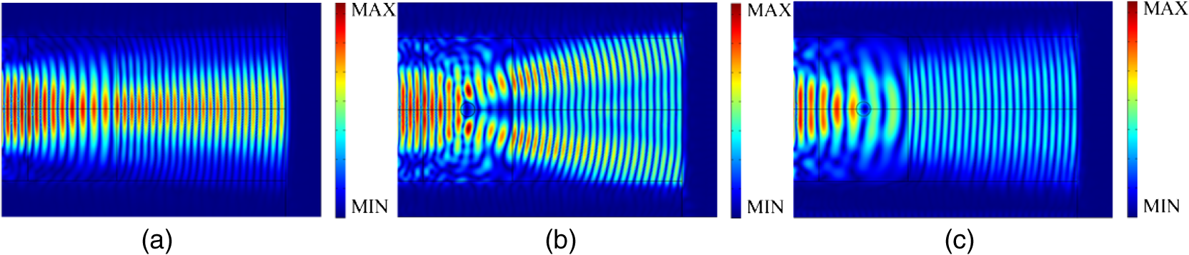
1.IntroductionThe coordinate transformation method, proposed for electromagnetic waves controlling and manipulating metamaterials by Leonhardt and Pendry et al., has been extended to elastic waves in recent years.1–4 Due to zero- and first-order approximation method itself and the impedance mismatch in the materials, the scattering phenomena, which refers to the frequency changes as waves pass through the media, is caused in the material design of wave propagation control.5 Generally, the operating mechanism of elastic waves is more complicated and difficult to control than electromagnetic waves.3 Furthermore, according to the existing control theory of wave propagation, some assumptions about the characteristics of the material, such as the anisotropy of the medium parameters, the continuity in the radial direction, and lossless dielectric are necessary but difficult to implement in practice. It is common that scattering exists in material designs of wave propagation control, including the directional cloak design of elastic waves. To reduce the scattering effects, many methods that simplify the sets of medium parameters or lower the complexity of the parameters are utilized.6–8 However, as a precondition, these scattering phenomena should be described adequately and grasped accurately, which, especially on the material boundary, only relies on macroscopic observation of the time domain waveform for qualitative conclusions without quantitative analysis.9 In analyzing the dynamic behavior and characteristics of the elastic media, the complexity and computational burden can be reduced by the models of homogeneous materials,10,11 which are inhomogeneous in practice.12 The deformation mechanisms of waves are complex in media, often elastic, plastic, nonlinear, and anisotropic. Meanwhile, the resulting models, based on material composition, structure, temperature, stress paths, history, and so on, are generally applied under strict conditions. Since scattering phenomena lead to spatial frequency changes, the fractional Fourier transform (FRFT)13,14 is a mathematically suitable tool to analyze scattering phenomena in both time and frequency domains and even in more complex scenarios of the propagation medium. Based on the FRFT analysis of scattering phenomena, we established the correspondence between the maximum matching order of transformation and the scattering, and provided the basis for assessing the material design of elastic wave propagation control. 2.Directional Cloak Design of Elastic WavesIt is complex and difficult to give a completely accurate description of the elastic waves’ control under normal conditions. But in some applications, the first-order approximate equations are sufficient. The governing equations of elastodynamics are where is the second-order stress tensor in a certain direction, is the frequency, is the density, is the displacement vector, and is the fourth-order elasticity tensor. Removing the tensor item and then obtaining Navier’s equation about the displacement of elastic wave controlIts first-order approximation is written as (without summation) where is the size of an element. As Eq. (3) is difficult to solve, it can be simplified to by zero-order approximation with symmetric elasticity tensor.In fact, Eq. (4) is proper only for high-frequency waves or slowly varying materials. That is, this approximation method can be used to design corresponding materials, which also results in scattering phenomena. The coordinate transformation method to design elastic wave propagation control devices is shown in Refs. 15 and 16. We provide the design method of linear change materials as follows. To ensure the materials change linearly in the design, we use an undetermined coefficients method to solve the transformation relationship, which is expressed as When the materials change from 1 to multiples of transformations, e.g., , the equation can be obtained.The factor of change materials can then be obtained by solving this equation. The material parameters of elastic waves vary in accordance with the above equations, and then the corresponding linear change materials can be obtained by the transformation method. In linear change materials, the spatial frequency of an elastic wave also varies linearly as it passes through the medium. The simulation results about the signal propagation with linear change media are shown in Fig. 1, where the constant scaling factor and the background media is structural steel with material parameters , , and . The obstacle has material parameters , , and . 3.Analysis of Fractional Fourier Transform and Its Scattering Effects on Directional Cloaks3.1.Fractional Fourier TransformThe scattering effect leads to the change of signal spatial frequency in dielectric materials, i.e., instantaneous frequency changes as the space varies. To analyze the nonstationary signal spatial frequency change, we use the FRFT method, a signal analysis tool with better convergence that is more focused on energy than the Fourier transform.13 The FRFT of a signal is defined by where is the rotation angle, is the fractional order of transformation, and is the transformation kernel.This means that the signal is expanded into a set of orthogonal basis of the transform kernel function space. Then the domain is the so-called fractional Fourier domain. The FRFT degenerates to a classical Fourier transform when . 3.2.Estimation Performance Comparison between Fractional Fourier Transform and Short Time Fourier TransformAn example illustrates that the FRFT has better convergence than the STFT with the following general quintic polynomial (the signal to match), as shown in Fig. 2 Fig. 2Fitting results of FRFT and STFT on a general quintic polynomial. (a) The original signal, (b) STFT estimation, and (c) FRFT estimation. 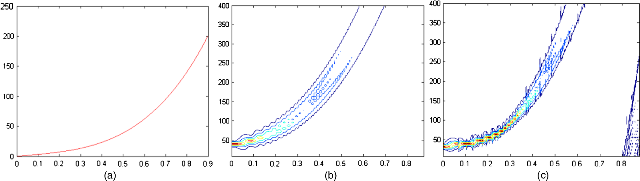 Figure 2(a) is the original polynomials to fit. Figures 2(b) and 2(c) are the fitting results with STFT and FRFT, respectively. As can be seen from the figures, FRFT has better focused features and a better estimation performance than STFT. 3.3.Fractional Fourier Analysis and ResultsTo transform the above spatial domain waveforms into the fractional Fourier domain, substitute the signals acquired from the materials into Eq. (7), and then get the spatial frequency diagram, as shown in Fig. 3. The fractional order change in the transformation is a search process to find the greatest undulation in frequency. We use a method, the so-called “first-rough and after-accurate scale,” to improve the frequency accuracy: first, scan the whole rotation angle range to find the rough maximum in the transform domain with a big fractional order step, then search the accurate maximum near the rough maximum with a small fractional order step. Fig. 3Analysis of scattering effects on directional cloaks. Horizontal: (a) without obstacles, (b) with obstacles but without cloaks, and (c) with both obstacles and cloaks. Vertical: (d) waveforms of intermediate position in the designed inhomogeneous materials; (e) 3-D diagrams of FRFT signals in (d) column, where -label is the transformation angle, -label is the original signal, and -label is the FRFT result; and (f) matching order of FRFT results. 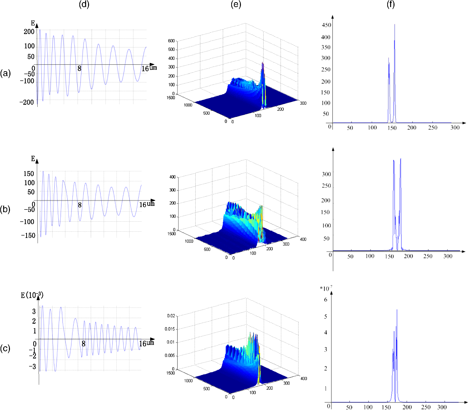 Figure 3(d) shows the signal waveform of the elastic wave propagation in the middle of the linear change materials. In the scenario of linear design changes of 1 to 2 times and without obstacles, the spatial frequency of the elastic wave in the middle of materials changed linearly. It is found from the waveforms in the middle of linear change elastic materials that the waveform is changed linearly. The frequency modulation rate is changed from [the basic waveform without obstacles as shown in Figs. 3(d)–3(a)] to [with the obstacle in the materials as shown in Figs. 3(d)–3(b)], and is improved to with the designed obstacle and cloak [Figs. 3(d)–3(c)]. The signal modulation frequency rate is greatly changed when there is no cloak. And when the cloak design is added, the signal is improved and is closer to the original signal. The three-dimensional (3-D) diagram of above signals FRFT is shown in Fig. 3(e). When there are no obstacles in the medium, the waveform is a linear frequency modulated signal. When there is an obstacle, the frequency modulation rate is changed. But after adding the cloak, it is better compared with the design without cloaks. Three cases of FRFT results with matching order are shown in Fig. 3(f). This figure shows that it is smooth in the spatial FRFT domain in the absence of obstacles [Figs. 3(f)–3(a)], and new frequency components are increased in the case of with obstacles [Figs. 3(f)–3(b)]. Nevertheless, the increased parts become focused with both obstacle and cloak scenarios [Figs. 3(f)–3(c)]. From the above results, whether in spatial domain diagrams or in FRFT transform domain diagrams, it can be seen that the signals are significantly improved after the cloak is added. 4.ConclusionBased on the method of the continuum theory, an elastic wave approximation cloak can be designed to improve the signals interrupted by obstacles. But scattering phenomena occur in the propagation process. FRFT is a suitable tool used in the signal processing with scattering variable parameters. FRFT clearly plays a very important role in the variable parameters signal processing, as it can not only analyze the change of signals and evaluate the design of material parameters, but also quantitatively illustrate the results of the transformation, thus providing support for the evaluation of the design methods. This paper studies the design of a simple device and the theoretical analysis using the zero- and first-order approximation method. In practical applications, it is required to further consider the impact of material factors, such as the size and shape effects on the scattering. AcknowledgmentsThis work was supported by the National Natural Science Foundation of China (61301089, 61471045, 61421001 and 61575022), Natural Science Research Fund of Education Department of Henan Province (15A140044), and Basic & Advanced Technology Research Fund of Henan Province (162300410200). ReferencesU. Leonhardt,
“Optical conformal mapping and dielectric invisibility devices,”
Science, 56
(12), 1
–4
(2006). SCIEAS 0036-8075 Google Scholar
J. B. Pendry, D. Schurig and D. R. Smith,
“Controlling electromagnetic fields,”
Science, 312
(5781), 1780
–1782
(2006). http://dx.doi.org/10.1126/science.1125907 SCIEAS 0036-8075 Google Scholar
Z. Chang, J. Hu and G. K. Hu,
“Transformation method and wave control,”
Acta Mech. Sin., 26
(6), 889
–898
(2010). http://dx.doi.org/10.1007/s10409-010-0386-8 LHHPAE 0567-7718 Google Scholar
X. Z. Hai,
“The form-invariance of wave equations without requiring a priori relations between field variables,”
Sci. China Phys. Mech. Astron., 57
(12), 2285
–2296
(2014). http://dx.doi.org/10.1007/s11433-014-5592-0 Google Scholar
J. Hu, X. Liu and G. Hu,
“Constraint condition on transformed relation for generalized acoustics,”
Wave Motion, 50
(2), 170
–179
(2009). http://dx.doi.org/10.1016/j.wavemoti.2012.08.004 WAMOD9 0165-2125 Google Scholar
A. M. AlMuhaidib et al.,
“Finite difference elastic wave modeling including surface topography,”
SEG Technical Program Expanded, 2941
–2946 ,
(2011). Google Scholar
M. Brun, S. Guenneau and A. B. Movchan,
“Achieving control of in-plane elastic waves,”
Appl. Phys. Lett., 94
(6), 061903
(2009). http://dx.doi.org/10.1063/1.3068491 APPLAB 0003-6951 Google Scholar
J. Mei et al.,
“Theory for elastic wave scattering by a two-dimensional periodical array of cylinders: an ideal approach for band-structure calculations,”
Phys. Rev. B, 67
(24), 841
–845
(2003). http://dx.doi.org/10.1103/PhysRevB.67.245107 PRBMDO 1098-0121 Google Scholar
J. Lee,
“Analysis of elastic wave scattering problems using volume integral equation method,”
J. Mech. Sci. Technol., 22
(22), 228
–239
(2008). http://dx.doi.org/10.1007/s12206-007-1113-7 Google Scholar
G. Labate, L. Matekovits and M. Orefice,
“Inverse scattering homogenization method for conformal metamaterial structures,”
in 2015 IEEE Int. Symp. on Antennas and Propagation and USNC/URSI National Radio Science Meeting,
63
–64
(2015). http://dx.doi.org/10.1109/APS.2015.7304417 Google Scholar
X. Lu, J. Hu and R. Tao,
“Enhanced fractional Fourier lens with isotropic transformation media,”
Opt. Eng., 52
(6), 060501
(2013). http://dx.doi.org/10.1117/1.OE.52.6.060501 Google Scholar
M. Tsang and D. Psaltis,
“Magnifying perfect lens and superlens design by coordinate transformation,”
Phys. Rev. B, 77
(3), 035122
(2008). http://dx.doi.org/10.1103/PhysRevB.77.035122 PRBMDO 1098-0121 Google Scholar
R. Tao, F. Zhang and Y. Wang,
“Fractional power spectrum,”
IEEE Trans. Signal Process., 56
(9), 4199
–4206
(2008). http://dx.doi.org/10.1109/TSP.2008.925579 Google Scholar
A. Sohn,
“Fractional Fourier transforms and their optical implementation. II,”
J. Opt. Soc. Am. A Opt. Image Sci., 37
(11), 2130
–2141
(1993). http://dx.doi.org/10.1364/JOSAA.10.002522 Google Scholar
J. Hu, Z. Chang and G. Hu,
“An approximate method for controlling solid elastic waves by transformation media,”
Physics, 84
(20), 201101
(2010). http://dx.doi.org/10.1103/PhysRevB.84.201101 PHYSGM 1943-2879 Google Scholar
C. Zheng et al.,
“Controlling elastic waves with isotropic materials,”
Appl. Phys. Lett., 98
(12), 121904
(2011). http://dx.doi.org/10.1063/1.3569598 APPLAB 0003-6951 Google Scholar
|