|
|
1.IntroductionFizeau interferometers with transmission flats or spherical references and mechanical phase shifts are among the most successful commercial optical interferometers and have a measurement repeatability better than 0.1-nm root-mean-squares (RMS). For better quality control, we are expecting to further improve the repeatability. Several systematic error sources1 can degrade the measurement repeatability. For instance, the intensity of a stabilized He–Ne laser source slowly varies periodically; its variation during a single phase measurement of 0.5 s, for example, is almost linear, with a relative amplitude variation of . However, this variation contributes to the degradation of the repeatability by and can also be compensated for using error-compensating algorithms.2,3 A spatially nonuniform phase shift across the observing aperture is common for a spherical test with a high numerical aperture (NA).4 Many error-compensating algorithms have been derived that can suppress these linear detuning errors in the phase modulation.4–9 For highly reflective test surfaces, such as silicon spheres () or metal-coated mirrors, multiple reflections and the correlation between the detuning error and the higher-order harmonic fringe signals become dominant error sources that have been discussed by several authors.6,9–12 Internally scattered light is another source of systematic error. Multiple reflections inside the collimator commonly produce circular fringes in the center of the observing aperture. Dust, point defects, and imperfect coatings in the polarization beam splitter or other components can also produce additional noise fringes or speckle patterns. A number of techniques have been reported to reduce the phase measurement error caused by the noise from scattered light.13–19 The noise fringes can be reduced by decreasing the lateral coherence length of the illuminating laser beam via transmission through a rotating ground glass diffuser13,15 or a rotating prism.14 In these techniques, the obliquely scattered rays inside the interferometer have their phases temporally averaged so that the interference fringes between the scattered rays and the reference beam reduce to the direct current (DC) offset. After the lateral coherence reduction, only paraxial reflections from the scattering points can produce interference fringes with the reference beam. These residual reflections cannot be eliminated in the ordinary phase-shift measurement because they are synchronized with the fundamental fringe signal. When the position of the dominant noise source is obvious, the noise can be reduced by temporally modulating the noise source position. Iijima16 demonstrated that noise from the stray light scattered from the aperture plate in a point-diffraction interferometer can be averaged by vibrating the plate along the optical axis. Nakayama et al.17 proposed a dual-phase-shift scheme (DPS), in which the object-reference surface pair was translated along the optical axis with respect to the collimator and other optical components to further modulate the signal phase. The measured phases at the different positions were averaged to reduce the scattered light noise. Synchronized DPS were proposed,18,19 in which the test surface is translated at a different speed from that of the reference surface during the phase measurement. The signal and noise fringes are then modulated with different frequencies in the observed interferogram, which is similar to source wavelength tuning interferometry. The signal phase can be separated from the noise components in the frequency space. These two DPS effectively reduce the reflection noise, especially noise from the multiple reflection inside the collimator. However, translating the reference and object surfaces together requires a sophisticated mechanical stage that is able to maintain the beam alignment during the translation. In this paper, we propose another DPS, in which only the test surface is translated between two successive phase measurements.20 Instead of using a pair of translations, this scheme is relatively simple and needs only a common piezoelectric transducer for object positioning. However, in this case, the spatial nonuniformity of the object’s phase shift should be taken into account in spherical surface testing, which is not necessary for the DPS from Ref. 17. Moreover, because the test surface is out of the null position of the confocal configuration during the translation, an additional primary aberration occurs in the measured phase. We show that the linear combination of the measured phases from several different object positions can eliminate the phase error caused by the nonuniform phase shift. We also show that symmetrical sampling of the object phases with respect to the null position can cancel the additional spherical aberrations. Experimental results demonstrate that the new dual-phase-shift analysis and the reduction of the lateral coherence length can efficiently decrease the internal reflection noise and compensate for the phase errors associated with the object positioning. 2.Dual-Phase-Shift Scheme in a Fizeau Interferometer2.1.Phase Modulation of the Test SurfaceFigure 1 shows the optical setup of the dual-phase-shift Fizeau interferometer. The source is a stabilized He–Ne laser with a wavelength of . The output from the source is transmitted through a rotating ground glass diffuser and a multimode fiber to reduce the lateral coherence of the beam. The detail of the lateral coherence reduction will be discussed in Sec. 2.3. The beam output from the fiber is then collimated, transmitted through a polarizer, and reflected by a polarization beam splitter. The beam is transmitted through a quarter-wave plate to change its polarization from linear to circular, expanded by a relay lens to 60 mm in diameter, and collimated to illuminate a reference transmission spherical surface and the test surface of an object. The reflections from both surfaces (we call “reference beam” and “object beam” respectively) return along the original path are transmitted through the quarter-wave plate again to attain an orthogonally linear polarization, pass through the polarization beam splitter, and combine to form interference fringes on the CMOS camera (Baumer, ). The test and reference surfaces are placed horizontally. Fig. 1Optical setup of the dual-phase-shift Fizeau interferometer for testing a spherical surface, where MO, POL, PBS, QWP, and PZT are the microscope objective, polarizer, polarization beam splitter, quarter wave plate, and piezoelectric transducer, respectively.  The reference surface is translated along the optical axis by a piezoelectric transducer (PZT1) in order to introduce phase modulation. Then, 13 interference images are recorded during the phase modulation over equal time intervals. The relative phase step between each frame is designed to be 60 deg. The object phase was calculated by a 13-frame phase-shifting algorithm that will be described in Sec. 2.2. In addition to the ordinary phase shift of the reference surface, the test surface is also translated by another transducer (PZT2) to introduce a relative phase shift of into the signal phase. We now discuss the elimination of noise fringes generated by a scattering point (“dust” or “multiple reflection” as shown in Fig. 1). For the convenience of the discussion, we represent the multiple reflection from the collimator as scattered light. Due to the reduction of the lateral coherence of the illuminating beam, only the paraxial component of the scattered light can interfere with the reference and object beams. Because we have three reflected beams: the reference beam, the object beam, and the reflection from the collimator, a combination of the three interference fringes is formed on the detector with an intensity defined by where and are the phase modulations introduced by the reference translation (by PZT1) and the object translation (by PZT2), respectively, and , , and are the interference phases between the reference and the object, between the reference and the collimator, and between the collimator and the object, respectively. The phase is the signal to be detected. For simplicity of the mathematical expression, we will henceforth abbreviate the spatial coordinates of and .First, we fix the object position () and execute a phase-shift measurement. During the phase shift of the reference surface, the first and last terms on the right-hand side of Eq. (1), including the amplitudes and , are constant and are eliminated by the 13-frame phase-shift calculation. Omitting these two DC terms, Eq. (1) can be rewritten as where phase is defined by During the phase-shift measurement, the phase modulation parameter is varied in equal phase steps of and the phase is detected by the 13-frame phase-shift algorithm. We can generally assume that the noise amplitude is much smaller than the signal amplitude and that . Expanding Eq. (3) in terms of the power of and keeping only the linear term givesUsing the approximation for gives the measured phase as Next, we translate the object by a fraction of the wavelength to modulate the phase . We then fix the object position again and execute the phase-shift measurement to obtain another phase . Then, we repeat the object translation and the phase-shift measurement. We denote the measured phase by at the th position of the object, where the parameter is denoted by .Finally, we construct a linear combination of the measured phases and expect to obtain the correct signal phase . Here, we introduce a spatial coefficient () and replace the phase-shift by () , because the amount of phase shift is not spatially uniform in the spherical test. For spherical objects, the optical path length along the marginal ray does not decrease by the same amount along the axial ray but rather decreases by a factor of , where is the NA of the test surface. The linear combination then becomes where we used the approximations and . We note that the coefficient depends on the position in the observing aperture and that the phase is arbitrary depending on the position of the scattering center.In order to obtain the correct object phase, the sampling amplitudes should satisfy the following six simultaneous equations: There are a number of solutions for the amplitudes depending on the phase shifts . Here, we assume that the amplitudes and the phase shifts satisfy the symmetric and antisymmetric relations, respectively, i.e., and for . The six equations then reduce to Eqs. (7), (8), and (12). Table 1 shows examples of the solutions for small .Table 1Phase-shift values for the object translation and the sampling amplitudes of the linear combinations.
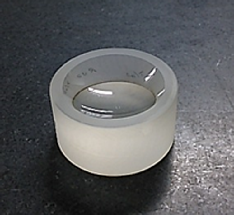
It is interesting to note that the simple average of the measured phases () is not the optimal solution for noise elimination. The minimum solution is three positional sampling () with a relative phase shift of . If the confocal position corresponds to a bright fringe pattern, we should shift the test surface by a quarter wavelength to the two neighboring dark fringe positions. We note that the present sampling amplitudes generally increase the susceptibility to random noise compared with the simple average with equal weight. The susceptibility to random uncorrelated noise is proportional to the root of the amplitude sum . For seven frames (), as an example, the susceptibility is, from Table 1, larger by 9.6% than that of the simple average. For spherical tests, the neutral position, , corresponds to the confocal position of the reference and test surfaces. The translation of the test surface from the confocal position (null fringe position) generally causes additional primary spherical aberration in the interference fringes. However, it is shown in the Appendix that the aberration increases linearly with the translation distance. Therefore, if the sampling of the object phases is symmetrical with respect to the neutral position, the aberrations can cancel each other out. In this experiment, we have assumed that the signal phases are summed up with symmetrical amplitudes (i.e., and ). The spherical aberration of the ’th signal phase can efficiently cancel with that of the ()’th signal phase. 2.2.13-Frame -Step Phase-Shift Algorithm for the Phase MeasurementAt each position in the observing aperture, the signal phase was calculated with a new 13-frame 60 deg-step phase-shifting algorithm. Although a triangle sampling window is immune to the spatial nonuniformity of the phase shift,21 it is more sensitive to harmonic noise compared with common sampling windows, such as the Hann or Hamming window.5 So, we derived a new sampling window to mitigate the harmonic noise using the averaging technique.1,7 An 11-sample triangle window is defined by . If we average the three windows with a relative shift of one sample, the resultant window becomes If we describe the phase shift by , for , the sampling amplitudes for the denominator and the numerator of the new algorithm are given by and , respectively. The resultant algorithm is obtained as where is the intensity of the ’th interference fringes.2.3.Reduction of Lateral Coherence LengthThe reflected or diffracted light from the scattering point is generally not paraxial, but it is distributed within a certain angle. The oblique component of the diffracted light can interfere with the reference beam and also with diffracted light from other scattering points. This multiple-beam interference noise is difficult to eliminate using the present phase-shift measurement because the amount of phase shift received by these oblique components is different from the designated value for the axial beam component. A common technique to eliminate the noise from the obliquely scattered light is the reduction of the lateral coherence length.13 In Fig. 1, the highly coherent beam output from the laser source is transmitted through a rotating ground glass diffuser and introduced to the interferometer through a multimode fiber. The transmitted light is randomized in its phase distribution along the observing aperture. A speckle pattern is then observed on the detector. When the ground glass is rotated, the intensity distribution of the speckle pattern changes very quickly during the frame capturing time of the detector. The correlation of the intensities at two arbitrary points on the detector becomes zero as a result of this time averaging, unless the two points are close enough to be within a single granule of the speckle pattern. Therefore, the coherence length in the lateral direction on the detector is effectively reduced to the order of the speckle size, as a result of the time averaging. Because the speckle granule size is inversely proportional to the NA of the extended light source, the lateral coherence length is inversely proportional to the core diameter of the multimode fiber. In this experiment, we used two multimode fibers of 200- and diameter, which generate lateral coherence lengths of 30 and 10 pixels on the detector, respectively. 3.ExperimentsFigure 1 shows the optical setup for the measurement. A spherical concave glass surface of 40-mm diameter and 30-mm radius of curvature (), shown in Fig. 2, is compared with the reference of a transmission spherical surface of 22-mm diameter (). The test object was placed horizontally and aligned in the confocal plane of the reference surface. The temperature within the laboratory was 23°C. After transmitting through the rotating ground glass diffuser and the multimode fiber of core diameter, the lateral coherence length of the illuminating beam was reduced to on the detector. At the confocal (null fringe) position of the test surface, the object phase was measured by shifting the reference surface with PZT1 and calculated using the 13-frame algorithm as shown in Eq. (14). Figure 3(a) shows the observed raw interferogram. The diameter of the test surface in the figure corresponds to 617 pixels on the detector. The analysis of the phase calculation was executed within its 90% diameter. Figure 3(b) shows the calculated phase distribution obtained after subtracting the first 36 Zernike polynomial terms and leaving the residual noise components. The phase errors caused by internal dust are indicated by the small red circles. We also indicate the phase error due to multiple reflections inside the collimator by the large red circle. The RMS phase values over the full aperture and within the three red circles were calculated to be 1.07-nm RMS and 1.57 nm, respectively. Fig. 3Observed raw interferogram of a spherical concave object, and measured phase map obtained after subtracting the 36 Zernike components: (a) observed raw interferogram where the phase calculation was executed within the 90% of the diameter shown by the white circle and (b) measured phase map where the scale bar denotes .  The test surface was translated out of the confocal position by along the optical axis and was then translated in the counter direction six times in equal steps of in order to change the phase of the interferogram by 90 deg each step. After each translation, the object phase was measured with the phase-shift measurement, and seven measured phases were obtained. Figure 4 shows the primary spherical aberrations (the eight Zernike coefficient) for the measured seven-phase distribution as a function of the test surface position. From the figure, it can be seen that the spherical aberrations increase linearly with the translation distance (or object phase shift ). The averaged spherical aberration over the seven positions () is , which shows good agreement with the aberration at the null position of . Therefore, we see that the symmetrical positioning of the test surface can balance and cancel out the additional spherical aberrations. Fig. 4Measured primary spherical aberrations for the spherical concave test object as a function of the test surface position.  The DPS object phase was calculated by summing the seven measured phases with the sampling amplitudes given in Table 1 for As a comparison, a simple averaged phase was also calculated, defined by Figures 5(a) and 5(b) show the calculated DPS phase and the averaged phase, respectively. By comparing with the result of single-positional measurement shown in Fig. 3(b), we see that the residual noise for full aperture was reduced from 1.07- to 0.76-nm RMS and to 0.89-nm RMS, respectively. The residual noise within the red circles was reduced from 1.57- to 0.87-nm RMS and to 1.49-nm RMS, respectively. It can also be observed that both the multiple reflection noise (as shown by the large red circle in the figure) and the dust noise (as shown by small red circles in the figure) are decreased more efficiently in the DPS phase than in the simple averaged phase. Fig. 5Dual-phase shift and simple averaged phases calculated from the seven phase measurements after subtracting the 36 Zernike components where the scale bar denotes (lateral coherence ): (a) Dual-phase shift and (b) seven-frame average. 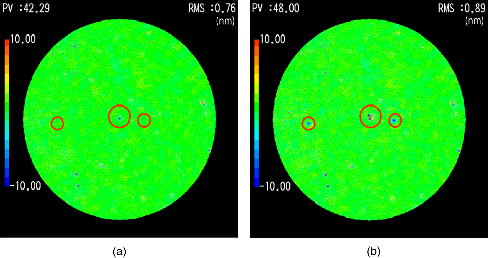 Table 2 shows the measurement repeatability for the single, seven-frame average and seven-frame DPS measurements. The repeatability was defined by over the 20 times measurements. The detector noise and background light noise was measured by a flatness test, which was smaller than 0.006-nm RMS. The repeatability after removing the tilt and defocus has similar values of for three measurements. This is because the aberration caused by the random motion in the mechanical translation of the test and reference surfaces is dominant compared with the scattered light noise. After removing the Zernike 36 components, the repeatability seems to improve with the present technique. Table 2Measurement repeatabilities 2σ for the single, seven-frame average and seven-frame dual-phase shift measurements calculated from 20 time measurements.
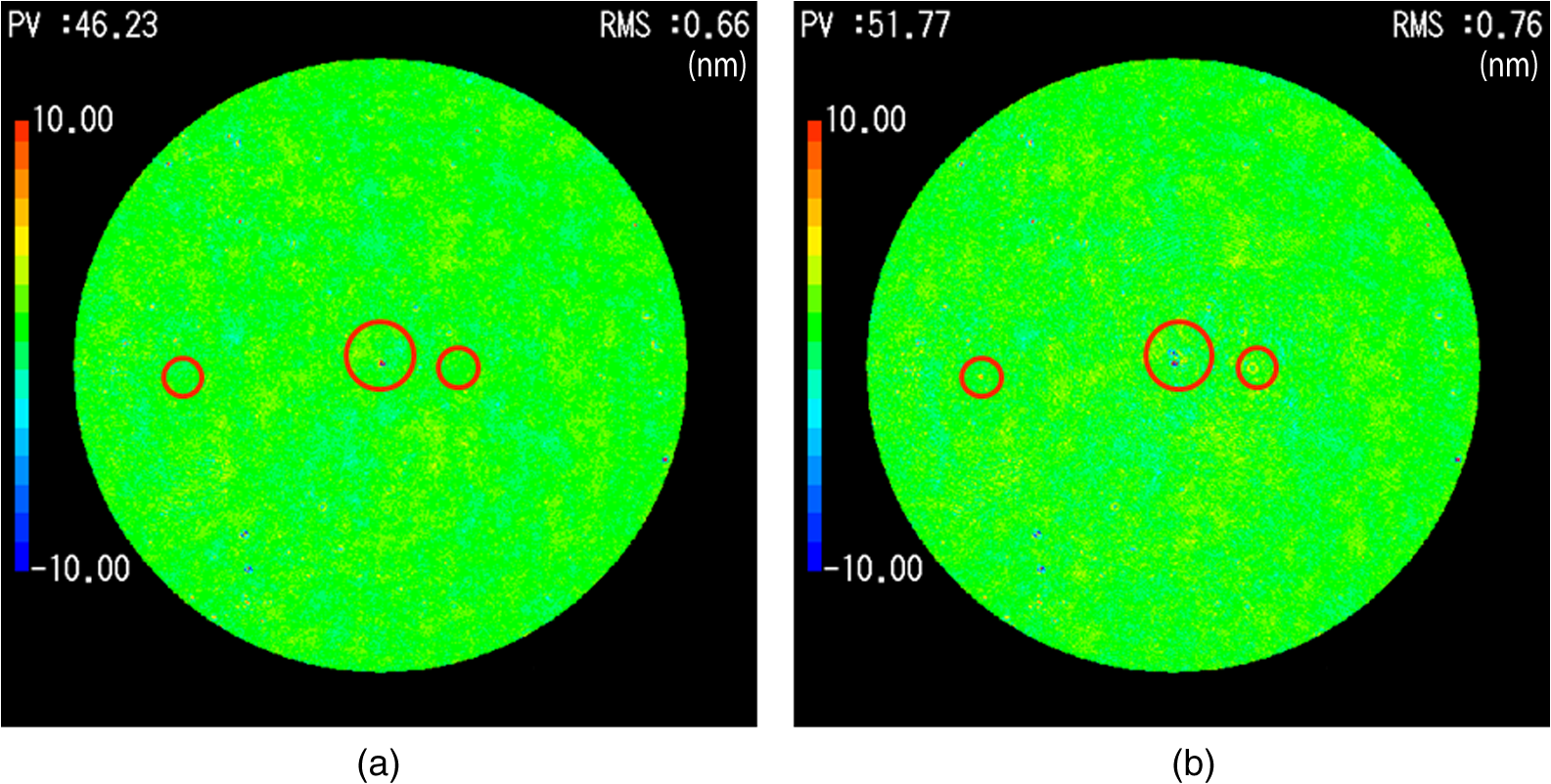
It is interesting to compare the present DPS technique with the conventional lateral coherence reduction technique. It was already discussed in Sec. 2.3 that the coherence length in the direction normal to the optical axis can be changed if we change the diameter of the extended source within which the phase distribution can be regarded as random. In this experiment, the extended source diameter is determined by the core diameter of the multimode fiber (see Fig. 1). We replaced the multimode fiber and changed the core diameters from 200 to , which reduces the lateral coherence length from 30 to 10 pixels on the detector. We repeated the same seven positional measurements as shown in Figs. 5(a) and 5(b). Figures 6(a) and 6(b) show the measured DPS phase and the averaged phase, respectively, for a lateral coherence length of 10 pixels. Compared with the results for a coherence length of 30 pixels [see Figs. 5(a) and 5(b)], the residual noise for full aperture was greatly reduced by both techniques, dropping to 0.66- and 0.76-nm RMS, respectively. Note that the multiple reflection noise (shown in the large red circle) is again not reduced efficiently by the simple averaging technique, whereas it is almost entirely removed by the present DPS technique. Therefore, we can conclude that the lateral coherence reduction reduces the scattering light noise but does not perfectly remove it. 4.DiscussionThe experimental results have shown that the present dual-phase-shift technique combined with conventional lateral coherence reduction can efficiently reduce the noise due to internally scattered light in the measured phase. However, we also observed that residual phase errors still remain that cannot be eliminated by the present technique. Here, we discuss the limitations of our technique. The origins of the noise can be identified if we can rotate each optical component around the optical axis relative to the other components. We rotated the reference surface, the test surface, and the microscope objectives by 90 deg (see Fig. 1), repeated the dual-phase shift measurements, and compared the results with the result shown in Fig. 5(a). Figure 7 shows the classified noise indicated by several color circles, which remains in the measurement of Fig. 5(a). The microscope objectives had no effect on the noise. The noises indicated by blue and orange circles are caused by the scattered light from the reference and the test surfaces, respectively. We can easily understand that the noise originating from the reference and the test surfaces cannot be eliminated, as it cannot be distinguished from the reference and the test surface profiles. The noise indicated by the yellow circle seems to come from the other optical components inside the interferometer, such as the collimator, the relay lens, the beam splitter, or imaging optics. The reflection beams from the reference and the test surfaces receive the same disturbance along the optical path to the detector, which causes no phase error to first order. However, there is higher-order interference component. Fig. 7Origins of the scattered light noise in the phase map measured by 7-frame dual-phase shift. Errors indicated by the blue and orange circles are caused by dusts on the reference surface and on the test surface, respectively. Errors indicated by yellow circles are from the other components of the interferometer. 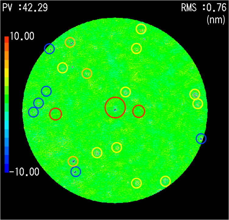 Figure 8 shows the schematic relationship between the lateral coherence length and the scattered light from the point defect existing in the intermediate optical components. The scattered light from the defect is distributed within a large angle. Scattered light at an angle of cannot produce interference fringes with the reference beam because they go beyond the laterally coherent region. The light scattered directly back toward the detector (shown by the blue lines) can combine with the reference beam to produce interference fringes whose elimination by the present dual-phase shift technique was already discussed. Fig. 8Schematic diagram of scattered light from the point defect and the lateral coherence length inside the interferometer. The first-order scattered light is indicated by blue lines and the second-order scattered light is indicated by red lines.  There is, however, higher-order scattered light, which has not yet been discussed. Second-order scattered light refers to the component that was reflected from the reference or test surface and then scattered by the defect. Figure 8 shows an example of second-order scattered light. Part of the reference beam is scattered at a small angle by the defect into the lateral coherence region (shown as the red lines in Fig. 8). This scattered light can interfere with the object beam and produce noise fringes. Similarly, the object beam is scattered by the defect into the coherence region and produces interference fringes with the reference beam. These two noise fringes are synchronized with the phase-shift parameter , and thus cannot be separated from the signal fringes by the present technique [see Eq. (1)]. The relative magnitude of these second-order fringes compared with the first-order noise fringes is on the order of , where is the reflection index of the reference and test surface. From Fig. 8, we can easily see that the second-order noise fringes decrease as the lateral coherence length decreases. Therefore, the present dual-phase shift technique is complementary to the conventional lateral coherence reduction technique for eliminating the internal scattered light noise. However, we also have to note that for small-aperture spherical lens testing, it is generally difficult to reduce the lateral coherence length to zero because of the limitation from the Lagrangian invariance theorem. 5.ConclusionsThe noise arising from internal scattering of light by dust, multiple reflections, and imperfect coating of the optical components degrades the measurement repeatability in a Fizeau interferometer. A new DPS is proposed in which the test surface is translated along the optical axis between successive phase-shift measurements, in addition to the ordinary phase-shift movement of the reference surface. A linear combination of the measured phases at different object positions is constructed to cancel the noise amplitudes in the measured phase. The spatial nonuniformity in the phase-shift increment arising in spherical tests is compensated for by suitable choices of the sampling amplitudes. The experimental results demonstrated that the present technique combined with the conventional lateral coherence reduction technique can efficiently reduce the phase errors caused by scattered light. It was also shown that the present technique is complementary to the conventional lateral coherence reduction method. AppendicesAppendixHere, we show that the spherical aberration increases linearly with the translation distance of the test surface. Figure 9 shows the ray components that transmit through the reference spherical surface at point , which are then converged to point and are reflected by the test spherical surface at point . Points and are the centers of the reference and test surfaces, respectively, and point is the converging point of the reflected rays. If we denote the vertex of the reference surface by and draw a sphere wavefront with center and radius , the reflected ray travels across this sphere and the reference surface at points and , respectively. Fig. 9Spherical aberration caused by the translation of the test surface out of the confocal position. The center of the test surface is shifted by distance from the center of the reference surface. Line DF is parallel to the optical axis HC.  The distance DE is the optical path difference between the marginal ray and the axial ray. If we note the axial distance DF between the reference surface and the sphere, the optical path difference DE can be expanded as to the distance ratio to give where is the NA of the reference surface, is the radial distance from the axis, , is the radius of curvature of the reference, and is the translation distance of the test surface from the confocal position.The first term in the right-hand side of Eq. (17) is a defocus component, which does not affect the aberration. The second term is the third-order spherical aberration. Noting that the translation is much smaller than the radius , the spherical aberration is reduced to From Eq. (18), we see that the aberration is linearly proportional to the translation distance .ReferencesJ. Schwider et al.,
“Digital wavefront measuring interferometry: some systematic error sources,”
Appl. Opt., 22 3421
–3432
(1983). http://dx.doi.org/10.1364/AO.22.003421 APOPAI 0003-6935 Google Scholar
R. Onodera and Y. Ishii,
“Phase-extraction analysis of laser-diode phase-shifting interferometry that is insensitive to changes in laser power,”
J. Opt. Soc. Am. A, 13 139
–146
(1996). http://dx.doi.org/10.1364/JOSAA.13.000139 JOAOD6 0740-3232 Google Scholar
Y. Surrel,
“Design of phase-detection algorithms insensitive to bias modulation,”
Appl. Opt., 36 805
–807
(1997). http://dx.doi.org/10.1364/AO.36.000805 APOPAI 0003-6935 Google Scholar
P. de Groot,
“Phase-shift calibration errors in interferometers with spherical Fizeau cavities,”
Appl. Opt., 34 2856
–2863
(1995). http://dx.doi.org/10.1364/AO.34.002856 APOPAI 0003-6935 Google Scholar
P. de Groot,
“Derivation of algorithms for phase-shifting interferometry using the concept of a data sampling window,”
Appl. Opt., 34 4723
–4730
(1995). http://dx.doi.org/10.1364/AO.34.004723 APOPAI 0003-6935 Google Scholar
K. Hibino et al.,
“Phase shiftings for nonsinusoidal waveforms with phase-shift errors,”
J. Opt. Soc. Am. A, 12 761
–768
(1995). http://dx.doi.org/10.1364/JOSAA.12.000761 JOAOD6 0740-3232 Google Scholar
J. Schmit and K. Creath,
“Extended averaging technique for derivation of error-compensating algorithms in phase-shifting interferometry,”
Appl. Opt., 34 3610
–3619
(1995). http://dx.doi.org/10.1364/AO.34.003610 APOPAI 0003-6935 Google Scholar
M. Servin, J. C. Estrada and J. A. Quiroga,
“The general theory of phase shifting algorithms,”
Opt. Exp., 17 21867
–21881
(2009). http://dx.doi.org/10.1364/OE.17.021867 OPEXFF 1094-4087 Google Scholar
P. de Groot,
“Correlated errors in phase-shifting laser Fizeau interferometry,”
Appl. Opt., 53 4334
–4342
(2014). http://dx.doi.org/10.1364/AO.53.004334 APOPAI 0003-6935 Google Scholar
P. B. Clapham and G. D. Dew,
“Surface-coated reference flats for testing fully aluminized surfaces by means of the Fizeau interferometer,”
J. Sci. Instrum., 44 899
–902
(1967). http://dx.doi.org/10.1088/0950-7671/44/11/303 JSINAY 0368-4253 Google Scholar
B. Zhao and Y. Surrel,
“Phase shifting: six-sample self-calibrating algorithm insensitive to the second harmonic in the fringe signal,”
Opt. Eng., 34 2821
–2822
(1995). http://dx.doi.org/10.1117/12.211676 Google Scholar
Y. Kim et al.,
“Surface profile measurement of a highly reflective silicon wafer by phase-shifting interferometry,”
Appl. Opt., 54 4207
–4213
(2015). http://dx.doi.org/10.1364/AO.54.004207 APOPAI 0003-6935 Google Scholar
P. S. Fairman et al.,
“300-mm-aperture phase-shifting Fizeau interferometer,”
Opt. Eng., 38 1371
–1380
(1999). http://dx.doi.org/10.1117/1.602180 Google Scholar
T. Kumagai, K. Hibino and Y. Nagaike,
“Dual phase-shift schemes for internal-reflection noise reduction in a spherical Fizeau interferometer,”
Proc. SPIE, 9960 99600C
(2016). http://dx.doi.org/10.1117/12.2237494 PSISDG 0277-786X Google Scholar
K. Hibino et al.,
“Phase-shifting algorithms for nonlinear and spatially non-uniform phase-shifts,”
J. Opt. Soc. Am. A, 14 918
–930
(1997). http://dx.doi.org/10.1364/JOSAA.14.000918 JOAOD6 0740-3232 Google Scholar
BiographyToshiki Kumagai is an optical engineer at the Olympus Corporation, Department of Equipment Technology. His current work includes the development of optical interferometers and the design and measurement of optical components. Kenichi Hibino is a research scientist at the National Institute of Advanced Industrial Science and Technology. He received his BS and MS degrees in physics from the University of Tokyo in 1979 and 1981, respectively, and his PhD in engineering from the University of Tokyo in 1998. His current research interests include optical interferometry, holography, and length metrology. |