|
|
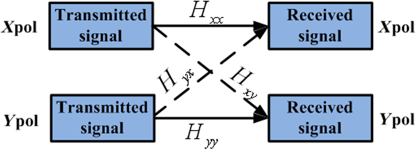
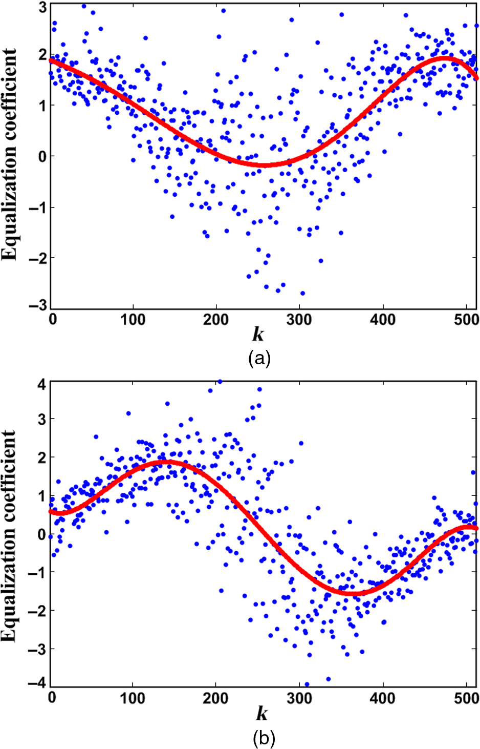
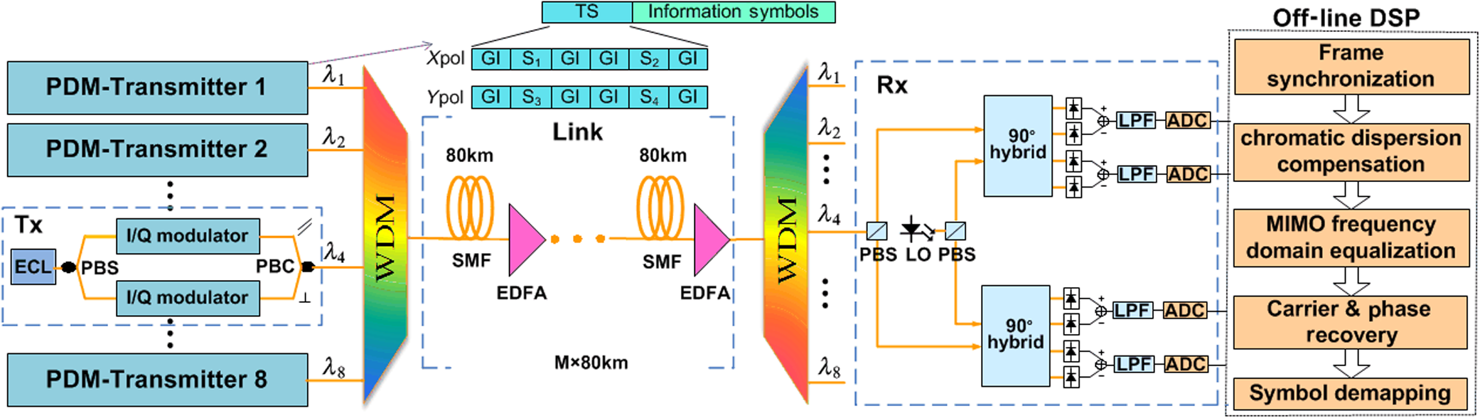
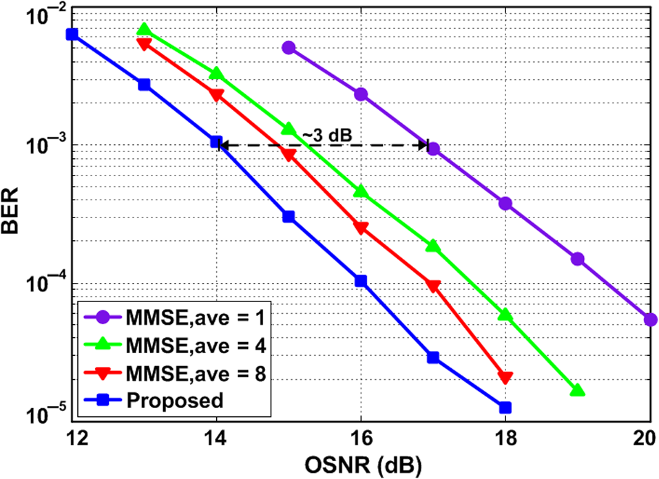
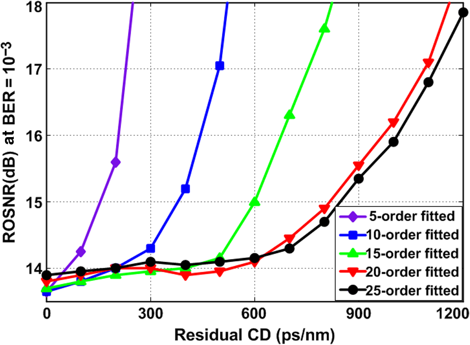
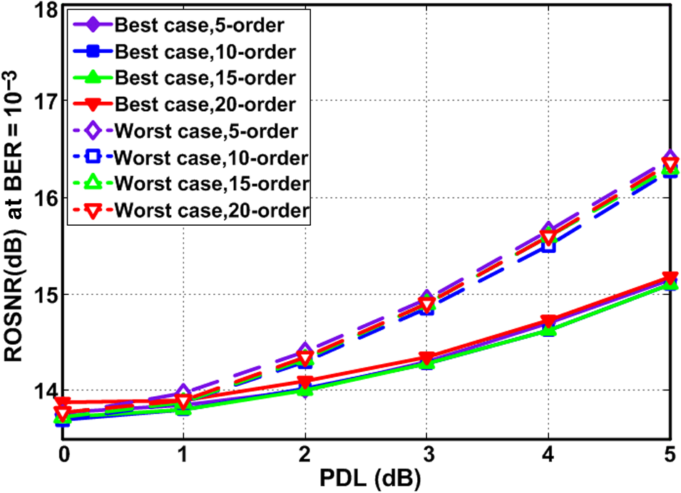
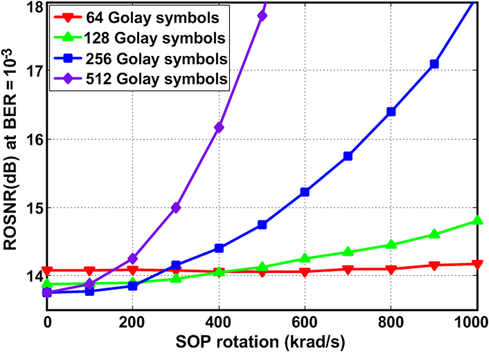
1.IntroductionPolarization-division multiplexing (PDM) and wavelength-division multiplexing (WDM) have enabled high spectrum efficiency and channel capacity in optical transmission systems.1–3 In coherent optical transmission systems, polarization multiplexed signals are usually demultiplexed by using coherent detection and further recovered through digital signal processing (DSP). Due to its low computational complexity, frequency-domain equalizer (FDE) has been widely employed in digital coherent receivers.4–6 Considering the time-varying channel induced by the transmission link, channel estimation before performing FDE is usually required, and one of the most effective estimation approaches is periodical transmission of known training sequences (TSs).7 Therefore, the FDE algorithms assisted by data-aided channel estimation, such as zero-forcing (ZF) equalizer and minimum mean-square-error (MMSE) equalizer, have attracted increasing interests. ZF equalizer can eliminate the crosstalk based on a weighted matrix. Such a method is relatively simple but does not consider the channel noise. Therefore, MMSE equalizer is proposed considering the channel noise, and a better equalization performance is obtained.8 Generally, the noise processed by the MMSE frequency-domain (FD) fractionally spaced equalizer (FSE) is assumed as additive white Gaussian noise (AWGN). However, due to the suppression of filters, the noise transmitted into the MMSE FD-FSE is no longer white but colored.9,10 In this case, the conventional MMSE FD-FSE based on AWGN would degrade the system performance. Therefore, an autocorrelation matrix of filtered noise is introduced into MMSE FDE to cope with colored noise in a known channel.11 On the other hand, MMSE FD-FSE for an unknown channel is studied as well by introducing knowledge of the optical and electrical filtering at the receiver.12 In this paper, an enhanced MMSE FD-FSE for the PDM coherent optical transmission system is proposed in the presence of colored noise. The 2-norm of the estimated channel matrix and polynomial fitting of equalization coefficients are introduced to mitigate the colored noise without requiring knowledge of the optical and electrical filtering. The proposed scheme is demonstrated in an WDM PDM-quadrature phase shift keying (QPSK) transmission system over a 1200-km single-mode fiber (SMF) link. Simulation results show that improvement of equalization performance is achieved compared to conventional MMSE FD-FSE at the bit error rate (BER) of . 2.System ModelPDM is an effective way to improve the transmission capacity, which makes the coherent optical transmission system equivalent to a multiple-input multiple-output system13 as shown in Fig. 1. Typically, the transmitted channel that is assumed to be linear or weakly nonlinear can be described by a matrix . is dependent on the transfer functions of the pulse shaper, chromatic dispersion (CD) effect, polarization mode dispersion (PMD) effect, polarization-dependent loss (PDL) effect, optical and electrical filtering, etc.12 Usually, the channel matrix contains four submatrices (i.e., , , , and ), and each submatrix is an diagonal matrix. The diagonal elements of submatrices denote the transfer function of the corresponding channel. In addition to the linear and nonlinear distortions of the channel, the transmitted signals could also be deteriorated by channel noise that is assumed as AWGN.14 Therefore, the received signals in FD can be expressed as where and . and represent -point fast Fourier transform (FFT) of the blocks of the time-domain transmitted signals and received signals, respectively. denotes the transpose of the matrix. indicates the FD noise of the -polarization and -polarization, which has been filtered by optical and electrical filters. Both , and are matrices.Typically, optical and electrical filters are widely employed to reduce noise. In this case, the filtered noise at the input of the MMSE FD-FSE is no longer white but colored. To accurately describe such filtered noise , the frequency response of filtering is also applied to the noise, and can be expressed as where , , where denotes the null matrix. Submatrix is an diagonal matrix and its diagonal elements denote the frequency response of optical and electrical filtering. is the FD channel noise of the -polarization and -polarization before filtering, which is usually assumed as AWGN.The equalized FD signal can be obtained by employing FDE and expressed as where is the equalization matrix that contains four submatrices (i.e., , , , and ), and all of the submatrices are diagonal matrices, in which each diagonal element denotes the equalization coefficient of the corresponding frequency component. After equalization, is converted into a time-domain signal by inverse FFT. Finally, the transmitted signals can be reconstructed by using carrier phase recovery and decision.3.Enhanced Fractionally Spaced EqualizationAs is well known, the FSE can realize low-timing phase sensitivity and reduce noise enhancement over symbol spaced ones.9 The enhanced MMSE FD-FSE is designed based on the detected signal12 that can be expressed as where , , where expresses the aliasing terms that appear due to downsampling and means that the first and second half diagonal elements of the submatrix have been mutual exchanged.MMSE FD-FSE is usually utilized to minimize the value of mean-square-error, and the error between the transmitted signal and the detected signal is given as Therefore, the cost function based on containing equalization matrix can be defined as where indicates the expectation value. and denote complex conjugate and complex conjugate transpose of the matrix, respectively. is a identity matrix. Since the transmitted signal is statistically independent of the channel noise, the last two terms in Eq. (6) are equal to 0.15 Thus, Eq. (6) can be simplified as where denotes the trace of the matrix, is the signal power, and is the channel noise power.To obtain the MMSE solution of , gradient calculation is defined by the partial derivative of the cost function as By setting the partial derivative of the cost function to zero, the matrix can be written as where represents the inverse of the matrix.After matrix operation, the MMSE fractionally spaced equalization matrix for each frequency tone () can be calculated as where , . is the frequency response of the optical and electrical filtering for each frequency tone, SNR represents the signal-to-noise ratio, indicates the absolute value operation, and is a channel matrix for frequency tone .To simplify the equalization matrix, the term in Eq. (10) can be approximately replaced by . In this case, the equalization matrix can be rewritten as where would require the knowledge of the optical and electrical filtering,10 which is hard to obtain in practical systems. Actually, the norm of the channel matrix is approximate to the frequency response of the optical and electrical filtering.10,12 Thus, the equalization matrix can be defined as where , which is the 2-norm of the channel matrix.The derivation of Eq. (12) is based on the fact that the channel matrix is irrelevant to the channel noise. However, in practical systems, the estimated channel matrix is distorted by channel noise. Furthermore, the 2-norm of the estimated channel matrix is also affected. Especially in the high-frequency component (corresponding to the stopband of filters), the value of is too small and leads to enlargement of the noise effect. Therefore, we introduce polynomial fitting to mitigate the noise effect to equalization coefficients. The polynomial fitting of equalization coefficients is shown in Fig. 2, with the blue dots being the calculated equalization coefficients corresponding to variable before fitting and the red curve being the polynomial fitting. The transmission distance is 1200 km and the optical SNR (OSNR) is 17 dB. Since the equalization coefficients are complexes, the real and imaginary parts of the equalization coefficients are fitted, respectively. The coefficients of p-order polynomial with variable are discovered to close to (i.e., ) in the sense of least squares. For Fig. 2, the order and points of polynomial fitting are 5 and 512, respectively. When the coefficients of the polynomial are discovered, the equalization coefficients of corresponding to variable can be obtained from the fitted polynomial, and then the noise effect can be effectively mitigated. 4.Simulation and ResultsFigure 3 shows the simulation setup for an WDM PDM-QPSK coherent optical transmission system using a VPI platform. Throughout the simulations, eight external cavity lasers with 100-kHz linewidth are operated on a 100-GHz frequency grid extending from 1550.4 to 1556 nm. The QPSK signal is generated by driving the IQ modulator with a binary 28-Gbaud electrical signal. The transmission link is composed of (i.e., ) spans of SMF that have dispersion parameter of , PMD parameter of , attenuation of , and nonlinear coefficient of . The fiber loss of each span is completely compensated using an erbium-doped fiber amplifier. At the receiving end, eight channels are separated by WDM demultiplexer, and the fourth channel is utilized to evaluate the system performance. The signal and the local oscillator (LO) are combined at the polarization diversity hybrid and then photodetected by the balanced photodetector. The wavelengths of LO are identical with the lasers at the transmitting end. After filtering by low-pass filters (i.e., Bessel filter, fifth order, 19 GHz), the electrical signals are digitized to two samples per symbol and processed by off-line DSP module. At first, CD compensation is implemented by the FD dispersion equalization. Subsequently, channel estimation is applied based on TS. The TS consists of two sequences and for -polarization (or and for -polarization), each of which has 256 Golay symbols,7 as inserted in Fig. 3. After each periodically transmitted TS, 12,288 information symbols are followed. As the channel estimation is accomplished, FD-FSE for polarization demultiplexing is employed. The FFT size of the equalizer is 512, and a 50% overlap save method is used. Finally, carrier phase recovery and symbol demapping are applied. To evaluate the influence of fitting order, the equalization performances of proposed scheme with different fitting orders in QPSK system after 1200-km transmission are shown in Fig. 4. A low-order polynomial (i.e., 3-order) cannot accurately fit the equalization coefficients, thus the equalization performance obviously declines. As the fitting order is increased, the equalization performance is promoted accordingly. When the fitting order rises to 5, the equalization coefficients are fitted accurately, and similar equalization performance is obtained compared to the 10-order and 15-order fittings, respectively. However, the polynomial fitting would slightly increase computational complexity. The computation complexity caused by polynomial fitting is real multiplications and () real additions, respectively. is the polynomial order. Considering the trade-off of computational complexity and equalization performance, a 5-order polynomial fitting is adopted, and about two real multiplications and two real additions per symbol for each frame are increased, respectively. Fig. 4Equalization performances of proposed scheme with different fitting orders after 1200-km transmission. 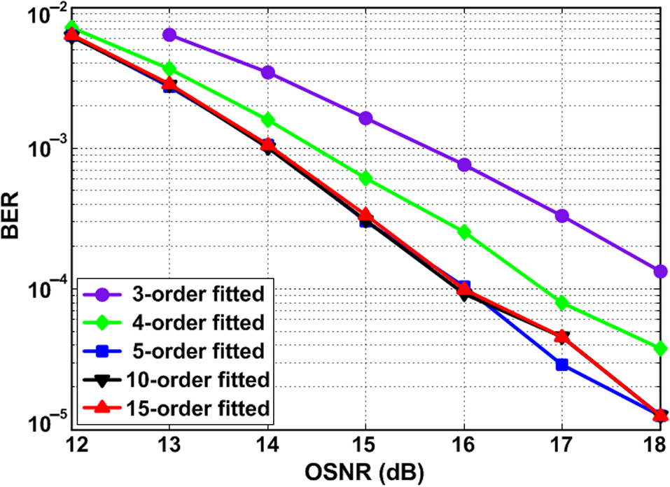 The equalization performances with different equalization schemes in a QPSK system after 1200-km transmission are calculated in Fig. 5. To suppress the noise effect, a simple and normally used approach is the linear averaging over several received training headers, which requires repeating the same TS and, therefore, further increases the overhead ratio.16 To evaluate the equalization performances with different equalization schemes, conventional MMSE FD-FSE with 4-time and 8-time averaging of channel estimation is simulated as a reference. With the same TS size, the proposed scheme (i.e., 5-order and 512-points fitting) can obtain improvement of equalization performance compared to conventional MMSE FD-FSE with one-time channel estimation at the BER of . Meanwhile, the equalization performance of the proposed scheme outperforms that of the conventional MMSE FD-FSE with 8-time averaging of channel estimation, and 87% of the overhead is reduced. The tolerance curves with respect to the residual CD of the proposed scheme are shown in Fig. 6. The residual CD leads to fluctuation of equalization coefficients. Therefore, a low-order fitting cannot completely match with the larger fluctuation of equalization coefficients when the residual CD increased. As shown in Fig. 6, higher-order polynomial fitting can obtain better tolerance with residual CD since the fluctuation has been matched. With the same required optical signal-to-noise ratio (ROSNR), the tolerable residual CD (i.e., ROSNR is 14.25 dB) of the 5-order and 20-order are 100 and , respectively. However, when the residual CD is small, a too high-order fitting would excessively track local variations of equalization coefficients caused by noise. Therefore, the equalization performance of the proposed scheme would slightly degrade. For the 20-order and 512-point polynomial fitting, about seven real multiplications and seven real additions per symbol for each frame are increased, respectively. The tolerance curves with respect to PMD of the proposed scheme are shown in Fig. 7. Analogous to residual CD, PMD also causes the fluctuation of equalization coefficients, and higher-order polynomial fitting can obtain better tolerance with differential-group delay (DGD). For a 5-order fitting, the proposed scheme can tolerate 15-ps DGD (i.e., ROSNR is 14.25 dB). Meanwhile, the tolerable DGDs for 10-, 15-, and 20-order fittings are 42, 59, and 72 ps, respectively. For both residual CD and DGD, since the fluctuation of equalization coefficients has been basically matched, the improvements of tolerance are limited when the fitting order rises to 25. Figure 8 shows the tolerances with respect to PDL of the proposed scheme with different fitting orders. For a PDM signal, the worst and best performance degradations occur when a PDM signal is 0 deg and 45 deg aligned to the axes of a PDL element, respectively.17 Therefore, to comprehensively investigate the effect of PDL on the proposed scheme, both the worst and best cases are considered. Since PDL does not cause fluctuation of equalization coefficients, similar equalization performances are obtained by different fitting orders. With a 5-dB PDL value, the OSNR penalty is about 1.4 and 2.6 dB in the best and worst cases, respectively. From the above analysis, only residual CD and PMD cause fluctuation of equalization coefficients. In fact, the DGD in long-haul coherent optical system is relatively small18,19 and can be tolerated by lower-order fitting. The order of fitting is mainly determined by residual CD. For system compensating CD well, a lower-order fitting is enough otherwise a higher-order fitting is required. With an identical overhead ratio, a longer TS would obtain a better equalization performance since it has more accurate channel estimation and equalization. However, the polarization tracking capability declines result from the longer length of the frame. In contrast, a shorter TS leads to a decreased equalization performance and better polarization tracking capability. To investigate the effect of polarization rotation speed, 64, 128, 256, and 512 Golay symbols are considered. Corresponding information symbols are adjusted to ensure identical overhead ratio. It should be noted that the TS consists of two Golay sequences for each polarization. Tolerances with respect to the state of polarization (SOP) rotation of the proposed scheme with different TS sizes are shown in Fig. 9. The order of fitting is 5. When the SOP rotation is , the best equalization performance is obtained by the proposed scheme with 256 Golay symbols, and a 0.3-dB improvement is achieved compared to the 64 Golay symbols case. Because the maximum polarization rotation speed in a commercial system is ,20 the polarization tracking performance of the proposed scheme with 256 Golay symbols can satisfy most coherent optical transmission systems. Considering the trade-off of equalization performance and polarization tracking capability, 256 Golay symbols are the optimum selection. For the system where the SOP changes ultrafast, the proposed scheme with 64 Golay symbols can be adopted since it has excellent polarization tracking capability. It should be noted that conventional MMSE FD-FSE with a shorter TS would also lead to a slight equalization performance degradation. 5.ConclusionAn enhanced MMSE FD-FSE with 2-norm of the estimated channel matrix and polynomial fitting has been proposed and investigated in an WDM PDM-QPSK transmission system in the presence of colored noise. Simulation results show that improvement of equalization performance is achieved compared to conventional MMSE FD-FSE. AcknowledgmentsThis research was supported by the National Natural Science Foundation of China (Nos. 61335005, 61325023, 61275068, and 61401378) and the Artificial Intelligence Key Laboratory of Sichuan Province (No. 2016RYJ05). ReferencesZ. Y. Chen et al.,
“Transmission of multi-polarization-multiplexed signals: another freedom to explore?,”
Opt. Express, 21
(9), 11590
(2013). http://dx.doi.org/10.1364/OE.21.011590 OPEXFF 1094-4087 Google Scholar
Y. Pan et al.,
“Transmission of three-polarization-multiplexed DPSK signals over 300-km fiber link,”
Opt. Lett., 41
(7), 1620
–1623
(2016). http://dx.doi.org/10.1364/OL.41.001620 OPLEDP 0146-9592 Google Scholar
Z. Y. Chen et al.,
“A highly flexible polarization demultiplexing scheme for short-reach transmission,”
IEEE Photonics J., 7
(6), 7905108
(2015). http://dx.doi.org/10.1109/JPHOT.2015.2497584 Google Scholar
M. Kuschnerov et al.,
“Data-aided versus blind single-carrier coherent receivers,”
IEEE Photonics J., 2
(3), 387
–403
(2010). http://dx.doi.org/10.1109/JPHOT.2010.2048308 Google Scholar
S. Faruk and K. Kikuchi,
“Adaptive frequency domain equalization in digital coherent optical receivers,”
Opt. Express, 19
(13), 12789
(2011). http://dx.doi.org/10.1364/OE.19.012789 OPEXFF 1094-4087 Google Scholar
O. Z. Chahabi et al.,
“Efficient frequency domain implementation of block-LMS/CMA fractionally spaced equalization for coherent optical transmissions,”
Photonics Technol. Lett., 23
(22), 1697
–1699
(2011). http://dx.doi.org/10.1109/LPT.2011.2166257 Google Scholar
A. V. Tran et al.,
“ optical coherent Pol-Mux single carrier system with frequency domain equalization and training sequences,”
Photonics Technol. Lett., 24
(11), 885
–887
(2012). http://dx.doi.org/10.1109/LPT.2012.2190052 Google Scholar
A. Lobato et al.,
“Maximum-likelihood detection in few-mode fiber transmission with mode-dependent loss,”
Photonics Technol. Lett., 25
(12), 1095
–1098
(2013). http://dx.doi.org/10.1109/LPT.2013.2257724 Google Scholar
B. J. Li et al.,
“Linear MMSE frequency domain equalization with colored noise,”
in IEEE 66th Vehicular Technology Conf.,
1152
–1156
(2007). http://dx.doi.org/10.1109/VETECF.2007.249 Google Scholar
F. Pittala et al.,
“Low-complexity training-aided MIMO frequency domain fractionally-spaced equalization,”
in Optical Fiber Communications Conf. and Exhibition,
(2014). http://dx.doi.org/10.1364/OFC.2014.Th2A.42 Google Scholar
S. O. Arık, D. Askarov and J. M. Kahn,
“Adaptive frequency domain equalization in mode-division multiplexing systems,”
J. Lightwave Technol., 32
(10), 1841
–1852
(2014). http://dx.doi.org/10.1109/JLT.2014.2303079 JLTEDG 0733-8724 Google Scholar
F. Pittala et al.,
“Training-aided frequency domain channel estimation and equalization for single-carrier coherent optical transmission systems,”
J. Lightwave Technol., 32
(24), 4849
–4863
(2014). http://dx.doi.org/10.1109/JLT.2014.2358933 JLTEDG 0733-8724 Google Scholar
Y. Han and G. F. Li,
“Coherent optical transmission using polarization multiple-input multiple-output,”
Opt. Express, 13
(19), 7527
–7534
(2005). http://dx.doi.org/10.1364/OPEX.13.007527 OPEXFF 1094-4087 Google Scholar
C. Zhu et al.,
“Digital signal processing for training-aided coherent optical single-carrier frequency domain equalization systems,”
J. Lightwave Technol., 32
(24), 4110
–4120
(2014). http://dx.doi.org/10.1109/JLT.2014.2364078 JLTEDG 0733-8724 Google Scholar
S. Reinhardt,
“Einträgerübertragung mit Frequenzbereichsentzerrung,”
Erlangen, Germany
(2007). Google Scholar
C. Zhu et al.,
“Low-complexity fractionally-spaced frequency domain equalization with improved channel estimation for long-haul coherent optical systems,”
in Optical Fiber Communications Conf. and Exhibition,
(2013). Google Scholar
C. Xie,
“Polarization-dependent loss induced penalties in PDM-QPSK coherent optical communication systems,”
in Optical Fiber Communications Conf. and Exhibition,
(2010). Google Scholar
C. B. Czegledi et al.,
“Modified digital backpropagation accounting for polarization-mode dispersion,”
in Optical Fiber Communications Conf. and Exhibition,
(2017). Google Scholar
J. Y. Wang, C. J. Xie and Z. Q. Pan,
“Matched filter design for RRC spectrally shaped Nyquist-WDM systems,”
Photonics Technol. Lett., 25
(23), 2263
–2266
(2013). http://dx.doi.org/10.1109/LPT.2013.2285227 Google Scholar
Z. Xiao et al.,
“ICI mitigation for dual-carrier superchannel transmission based on m-PSK and m-QAM formats,”
J. Lightwave Technol., 34
(23), 5526
–5533
(2016). http://dx.doi.org/10.1109/JLT.2016.2624758 JLTEDG 0733-8724 Google Scholar
BiographyMing Hao received his MS degree from the University of Electronic Science and Technology of China in 2011. He is currently working toward his PhD in the Center for Information Photonics and Communications, Southwest Jiaotong University, China. Meanwhile, he is a lecturer at the School of Automation and Information Engineering, Sichuan University of Science and Engineering. His research interests include digital signal processing (DSP) and high-speed optical transmission. Lianshan Yan received his PhD from the University of Southern California, Los Angeles. He is currently a full professor at Southwest Jiaotong University, Chengdu, China. He is the author and coauthor of more than 200 papers published in prestigious journals and conference proceedings, including seven invited journal papers and more than 30 invited talks. He is a fellow of the Optical Society of America (OSA) and a senior member of the IEEE. Anlin Yi received his PhD in communication and information system from Southwest Jiaotong University, Chengdu, China, in 2013. He is now with the School of Information Science and Technology, Southwest Jiaotong University. His current interest involves optical signal processing and high-speed optical transmission. Lin Jiang received his BS degree in electrical and information engineering from Tibet University, Lhasa, China, in 2012. He is currently working toward his PhD at Southwest Jiaotong University. His interests include the application of DSP technologies to optical communication systems. Yan Pan received his BS degree in physics from Yangtza University, JingZhou, China, in 2012. He is currently working toward his PhD at Southwest Jiaotong University. His interest involves microwave photonics and optical fiber communication systems. Wei Pan received his PhD from Southwest Jiaotong University, Chengdu, China, in 1999. He is a professor and the Dean of the School of Information Science and Technology, Southwest Jiaotong University. He has published over 100 research papers. His current research interests include semiconductor lasers, nonlinear dynamic systems, and optical communication. He is a member of the OSA and the Chinese Optical Society. Bin Luo received his PhD from Southwest Jiaotong University, Chengdu, China, in 1995. He is currently a professor at the School of Information Science and Technology, Southwest Jiaotong University. He is the author or coauthor of more than 80 research papers. His research interests include semiconductor optical amplifiers and optical communication. |