
|
|
|
Photometric techniques1, 2, 3, 4 used to measure the optical constants of materials are easily adapted to obtain spectra of the optical constants and are suitable to be used with thin films. The accuracy is typically on the second or third significant digit. With adequate instrumentation the measurement of the reflectance and transmittance of a layered sample can be measured with relatively high precision (commonly of about 0.1%). Also, robust inversion algorithms have been devised to obtain the optical constants and thickness of thin absorbing films from a few optical transmittance measurements.5 However, in all reported photometric techniques, the inversion of the experimental data relies on the use of Fresnel reflection coefficients; and surface roughness, scratches, or small particles on the surface may introduce large errors. In fact, in many cases the surfaces of a sample material do not have optical quality. In this letter, we describe a simple and accurate method to determine the refractive index spectra of an absorbing layer that is less sensitive to the surface conditions than other techniques. Consider a slab with a complex refractive index and an optical beam incident at an angle . If the slab absorbs most of the incident light in a single pass, we can ignore multiple reflections within the slab. It is not difficult to show that in this case the intensity of the transmitted beam is given by where is the intensity of the incident beam, is the thickness of the slab, is the wave number in a vacuum, and and are the transmittance coefficients of the interfaces of the slab,where , , is the angle of incidence, and we have assumed that the refractive index of the incidence medium is one. If we suppose , and expand Eq. 2 in a power series of and neglect terms of order we have where . Thus, is given by the usual Snell’s law with the real part of the refractive index of the slab.The method proposed in this letter consists of measuring the exponential decay factor of the transmittance, , at two angles of incidence, and , and then solving for the real part of the refractive index of the slab as where . Note that the determination of from Eq. 3 does not require knowledge of the film thickness, nor does it depend on the validity of Fresnel relations at the interfaces of the layer system. Now, to measure only the exponential factor we must normalize the transmittance measurements given by Eq. 1 by the factor . This factor must be estimated by additional measurements at angles of incidence, and .The error in determining will come from the errors in estimating the factors . A thorough analysis of the errors will be presented elsewhere. Nevertheless, to give an idea of the attainable accuracy of the method, we plot in Fig. 1 the relative error in obtaining as a function of the absorbance of the layer for a few values of the relative error on measuring the exponential decay factor . Fig. 1Relative error on the refractive index, , versus the absorbance of the sample assuming and for a relative error in the values of and of: (solid line), and (dotted line), and (dashed line). 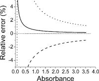 We can see that if the relative errors for both and 2 are similar and less than 2%, and if the absorbance is larger than 0.6, that is, a transmittance on normal incidence of less than 54%, then the error is less than 1%. In order to demonstrate the viability of the method in practice, we measured the refractive index of water in the wavelength range of . We used a thin rectangular cell made of glass slabs filled with distilled water and fixed on top of a goniometer. The thickness of the cell was about . However, we did not measure it precisely since the method does not require knowing the layer thickness. We added a small amount of black ink to the water to reduce the transmittance at normal incidence to less than 50% for all wavelengths in the specified range. To measure the transmittance we used a white light beam incident at a fixed angle with respect to the normal to the entrance facet of the cell. The light beam was generated with a white light source (BPS100 BWTEK Inc.) coupled to a pigtailed optical fiber. The beam was transmitted through the cell and collected by a -diameter optical fiber coupled to a miniature spectrophotometer (HR2000 Ocean Optics). Transmitted spectra were measured at two angles of incidence for the absorbing and pure water. These latter spectra are equal to the factors and were used to normalize the transmittance spectra of the absorbing water solution at the corresponding angle of incidence. It is worth mentioning that the glass cell was not of optical quality nor was it cleaned by any special procedure. As a matter of fact we measured the factor for the empty cell used in our experiment and found that it deviated appreciably (around 5% at normal incidence) from the predictions of the usual formulas based on the Fresnel reflection and transmission coefficients. The reason is that the interfaces of the cell were not of optical quality. In Fig. 2 we plot the refractive index calculated using Eq. 3 for wavelengths within the range . In the inset of this figure we show the normalized transmittance spectra at and . Finally, in Fig. 3 we plot the errors of the calculated refractive indices. These were obtained by comparing our results with reference data for the refractive index of water at . We can see that the relative error using an adjacent averaging smoothing over in wavelength oscillates around 0.3% from and only reaches 1.4% at the lowest wavelength. Since the present method is a photometric technique, this error is actually very low and is already useful to characterize absorbing films used in optical devices. Fig. 2Refractive index versus wavelength from measurements (solid line) and reference data at (symbols). The normalized transmittance spectra of the sample are shown in the inset. 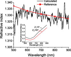 Fig. 3Relative error on the refractive index for raw data (dotted line) and using an adjacent averaging smoothing over in wavelength (solid line). 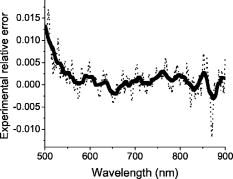 The application of this method to solid films will require a different technique to estimate accurately the normalization factors at each angle of incidence. Using TM polarized light and angles of incidence near the angle of minimum reflectance (due to the Brewster effects) will probably be convenient. The accuracy obtained by our method in the absence of high-quality surfaces is comparable to that of other photometric techniques when they are applied to samples with optical quality surfaces. However, our method is applicable to only highly absorbing layers. AcknowledgmentsWe are grateful to Asur Guadarrama Santana for technical support. We also acknowledge financial support through projects PAPIIT IN109702 and IN108402-3 from Dirección General de Asuntos del Personal Académico from Universidad Nacional Autónoma de México. ReferencesT. Babeva,
S. Kitova, and
I. Konstantinov,
“Photometric methods for determining the optical constants and the thicknesses of thin absorbing films: selection of a combination of photometric quantities in the basis of error analysis,”
Appl. Opt., 40
(16), 2675
–2681
(2001). 0003-6935 Google Scholar
G. H. Meeten and
A. N. North,
“Refractive index measurement of absorbing and turbid fluids by reflection near the critical angle,”
Meas. Sci. Technol., 6 214
–221
(1995). https://doi.org/10.1088/0957-0233/6/2/014 0957-0233 Google Scholar
Y. Lu and
A. Penzkofer,
“Optical constants measurements of strongly absorbing media,”
Appl. Opt., 25
(2), 221
–225
(1986). 0003-6935 Google Scholar
E. G. Bortchagovsky and
U. C. Fischer,
“Method for determination of the dielectric function of a thin absorbing film on variable substrates from transmission spectra,”
Appl. Opt., 42
(34), 6915
–6918
(2003). 0003-6935 Google Scholar
B. B. Meshkov and
P. P. Yakovlev,
“Determining the parameters of absorbing films,”
J. Opt. Technol., 70
(10), 757
–759
(2003). 1070-9762 Google Scholar
|


